Why Use Hex Elements in Your FEA?
In this article, we compare tetrahedron and hexahedron elements and show an example of why the latter can be important to implement into your FEA (Finite Element Analysis) studies.

TETRAHEDRON ELEMENTS
FEA tools like SOLIDWORKS Simulation use triangle-like tetrahedron (TET4) elements to mesh models (Figure 1).
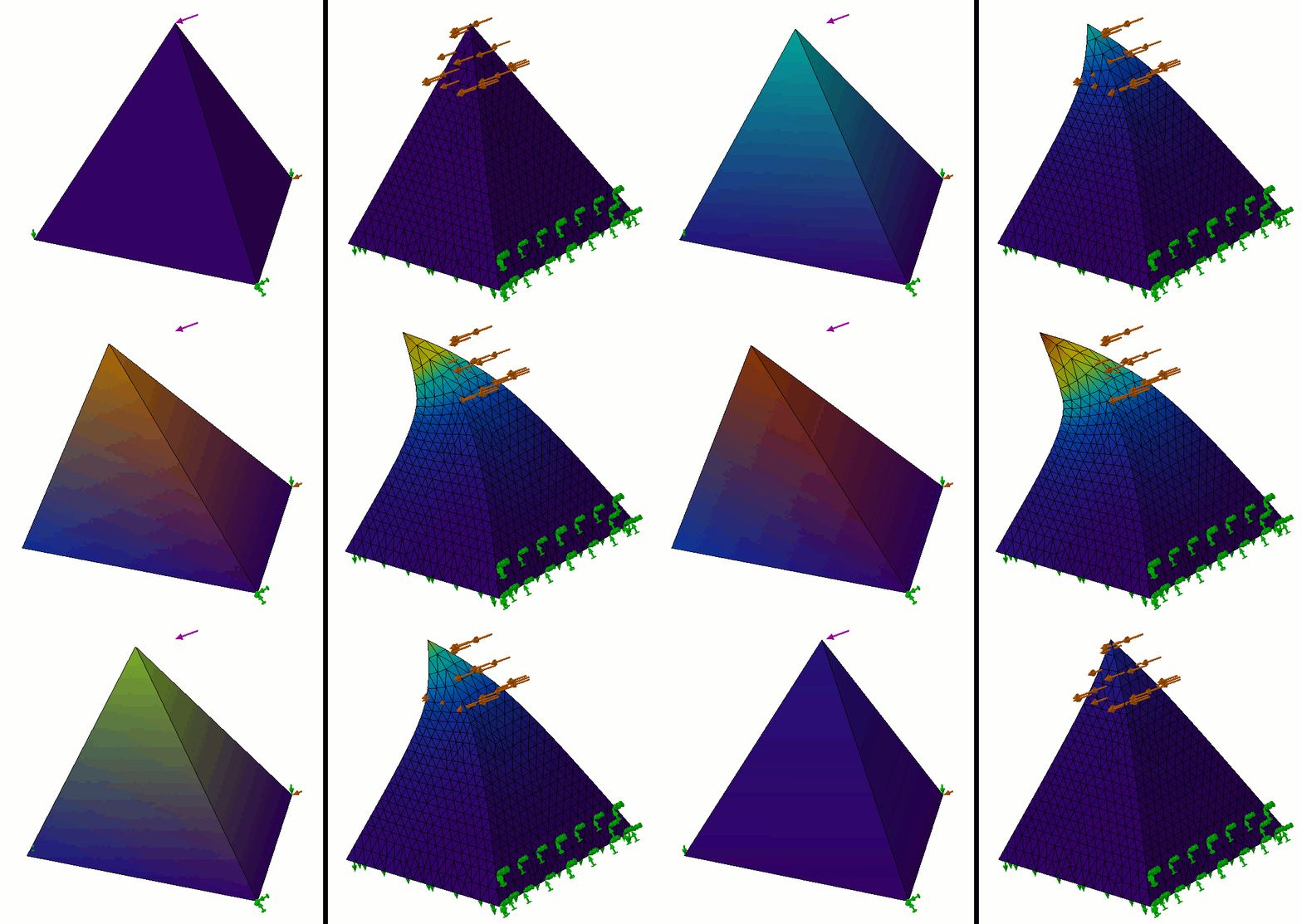
Figure 1 – Left: Single TET4 element deformation; Right: 10,000 TET4 element deformation
This element type is great when users do not want to spend a lot of time meshing their models.
Tetrahedron meshing can be automated by software developers effectively and sometimes the only thing the user must be conscious of is simple: throw more elements at the problem to make it more accurate until I run out of time.
This element’s versatility and ease of use rely on the principle that all shapes can be approximated reliably as triangles.
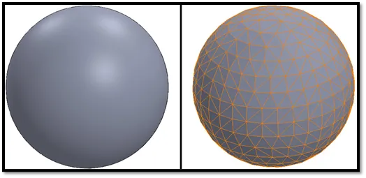
Figure 2 – Left: Spherical geometry; Right: meshed with TET4’s
HEXAHEDRON ELEMENTS
Advanced FEA tools like SIMULIAworks include additional element types that give users more control over their meshes so they can optimize the solve time. One popular element is the square-like hexahedron (HEX8) element.
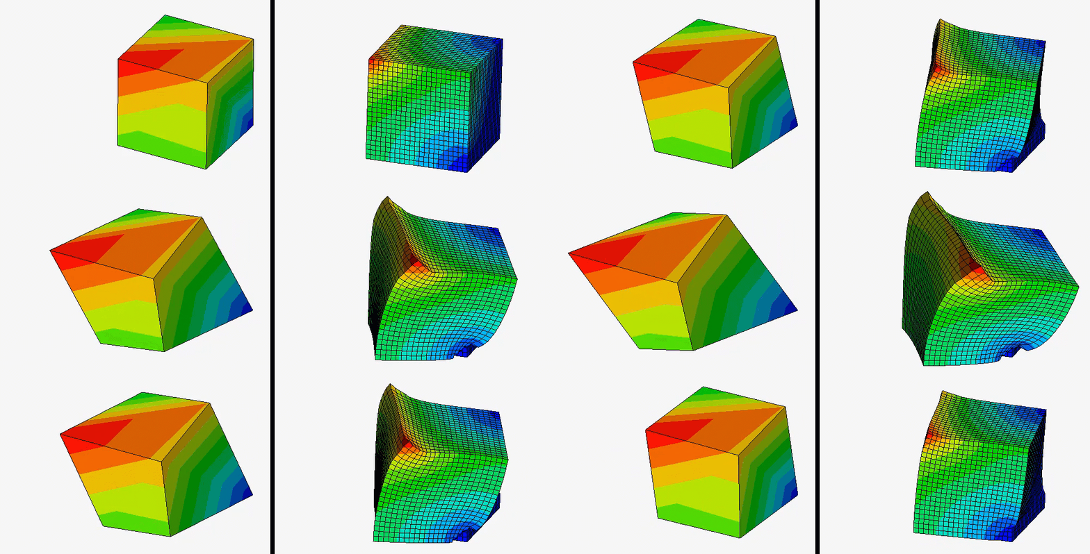
Figure 3 – Left: Single HEX8 element deformation; Right: 10,000 HEX8 element deformation
This element type has more stringent requirements for a couple of reasons:
- Not all shapes can effectively be approximated with squares so mixed meshing is frequently required.
- Users will need to identify natural surfaces on which to orient the elements.
- More feedback may be required for more complex shapes, so for some geometries, it is not practical to use hexahedrons.
However, when this element is applied, it can be worth the additional time required to configure them.
Hexahedron vs. Tetrahedron IMPACT Example
To compare the tetrahedron to the hexahedron element, I ran a simple impact test in a few different FEA tools. I scaled the mesh size so that it took approximately 1000 seconds to solve each study. Here were my results:
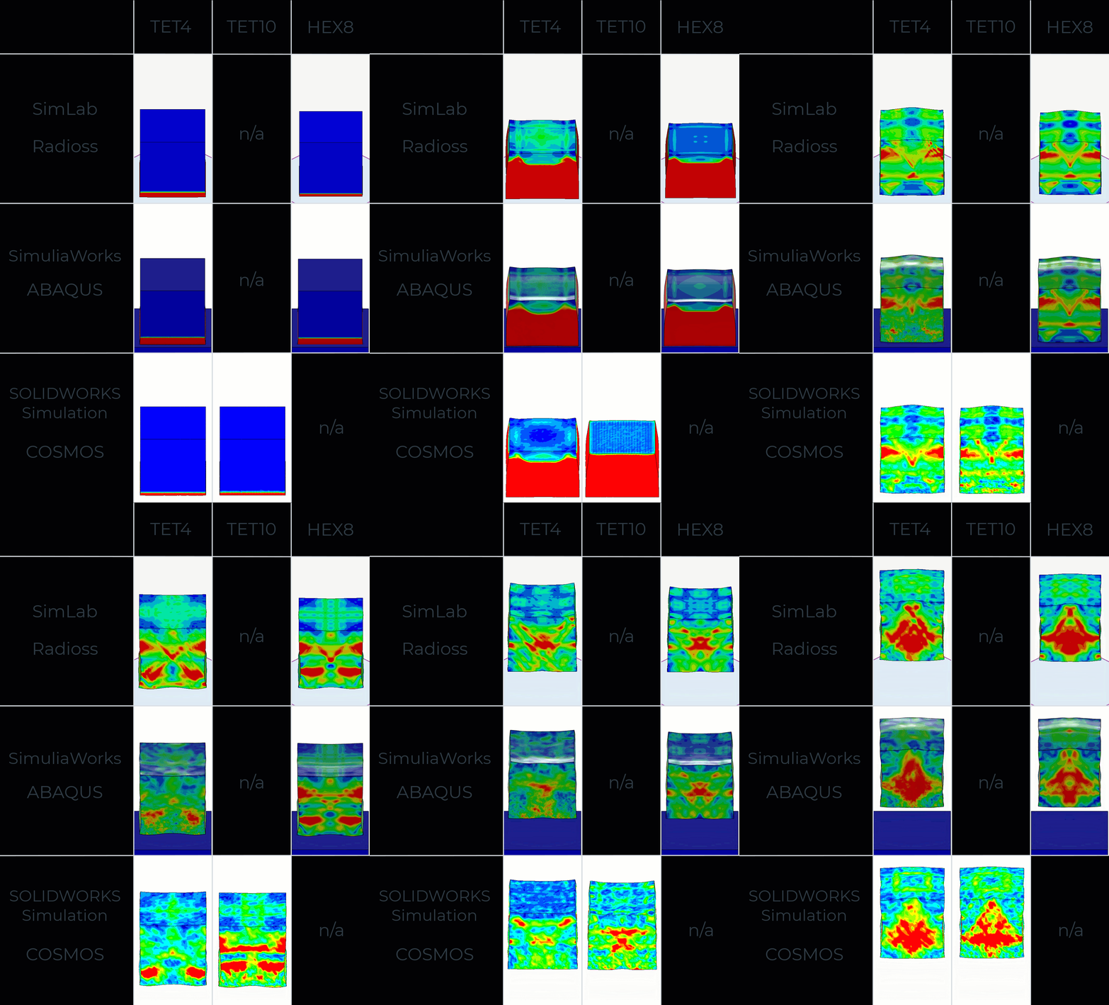
Figure 4 – What do results look like when we scale the mesh so that each takes about 1000 seconds to solve each study?
Look carefully at the side-by-side comparison in Figure 5. What type of mesh do you think performs best?
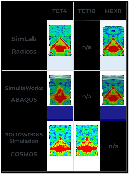
Figure 5 – Which type of mesh seems to perform the best?
In this impact case, there seems to be a lot of numerical noise on the tetrahedron element. Even the higher order TET10 elements seem to do relatively poorly and arguably perform worse than the TET4’s. This may explain why some advanced FEA tools do not support TET10’s for impact studies.
Full details of the study can be seen here, but a quick summary is shown below:
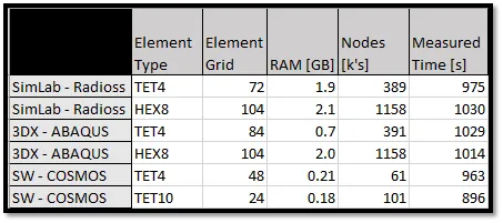
Figure 6 – Summary mesh and resource requirements
CONCLUSION
Hex elements offer a more efficient solution strategy for some classes of problems. Often the higher degree of local deformations occurring in an impact study might create a large benefit from using these elements.
However, for running simple static analyses, users may prefer moving quickly past the meshing phase. Tetrahedrons are a great solution for this case if deformations are not globally complex.

About Shaun Bentley
Shaun Bentley is passionate about applied mathematics and engineering, which led him to pursue and understand real world applications of FEA, CFD, kinematics, dynamics, and 3D & 2D modeling. He teaches many simulation classes to both new and advanced users attending training at GoEngineer. Since 2006, Shaun has been working with simulation tools to solve real world engineering problems. With every new project, he seeks to find ways to push simulation to its uppermost limits, even going so far as to write bespoke code and macros. He has passed the Michigan FE exam and mentors or consults for virtually any industry that uses SOLIDWORKS, especially automotive and automated tools. He is a speed 3D modeling champion and one of the first Certified SOLIDWORKS Experts in Simulation in the world.
Get our wide array of technical resources delivered right to your inbox.
Unsubscribe at any time.