Creaform Scan-to-CAD
Integrate 3D scan data into your CAD and Additive Manufacturing process
The fastest path from 3D scans to your CAD and 3D printing workflow
Creaform Scan-to-CAD is a user friendly and affordable reverse engineering software. The main purpose of the software is to obtain reference geometry that can be imported into any CAD platform, with direct transfer to SOLIDWORKS, Autodesk, and Solid Edge. Creaform Scan-to-CAD includes various mesh editing tools to help you finalize a scan for 3D printing. You can also create surfaces or solid bodies from a mesh. The entire software is on a single toolbar that makes it easy to learn.

The perfect complement to your Creaform 3D scanner
Creaform Scan-to-CAD is intuitive but powerful and acts as a companion to your 3D CAD platform. The simplified software only features the tools necessary to complement your existing CAD software. It’s as simple as one right-click and Scan-to-CAD will transfer parametric entities into your CAD suite.
Tools
Creaform SCAN-TO-CAD
Advanced plug-in tools.
Reference Entities
Create reference entities for reverse engineering or basic measurements. Using a variety of selection tools, users can pick points and triangles directly on the mesh. Reference entities include planes, lines, points, and slots and users can also generate standard 3D shapes such as cylinders, cones, and spheres. 2D reference entities can be transferred to SOLIDWORKS as sketches while 3D shapes will be transferred as solid bodies.
Alignment Wizards
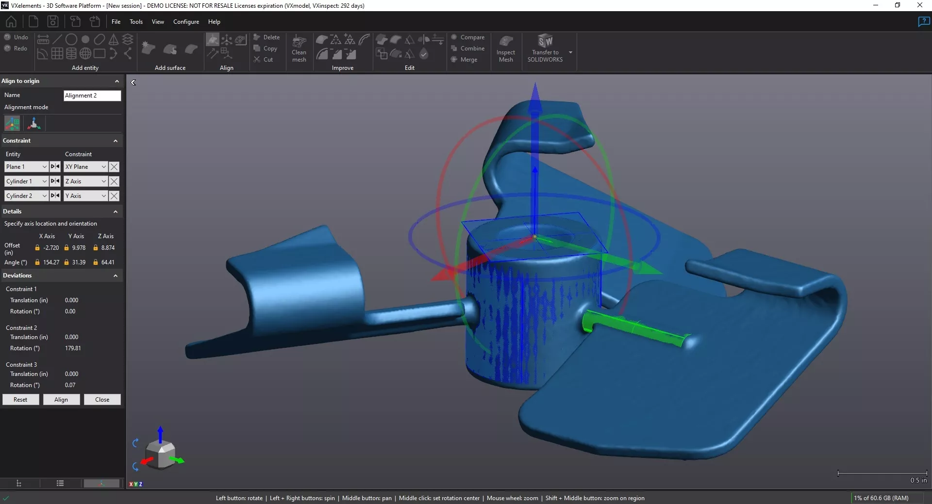
Align scan data to the origin using several methods. Using reference entities, users can assign constraints to planes or axis on the mesh. A preview allows you to modify an alignment before you accept it. If you have multiple scans you can align them to each other. Options include using targets, surface best fit, or global registration. With either of these methods, users can pick points manually or use the auto-align tool.
Mesh Improvement
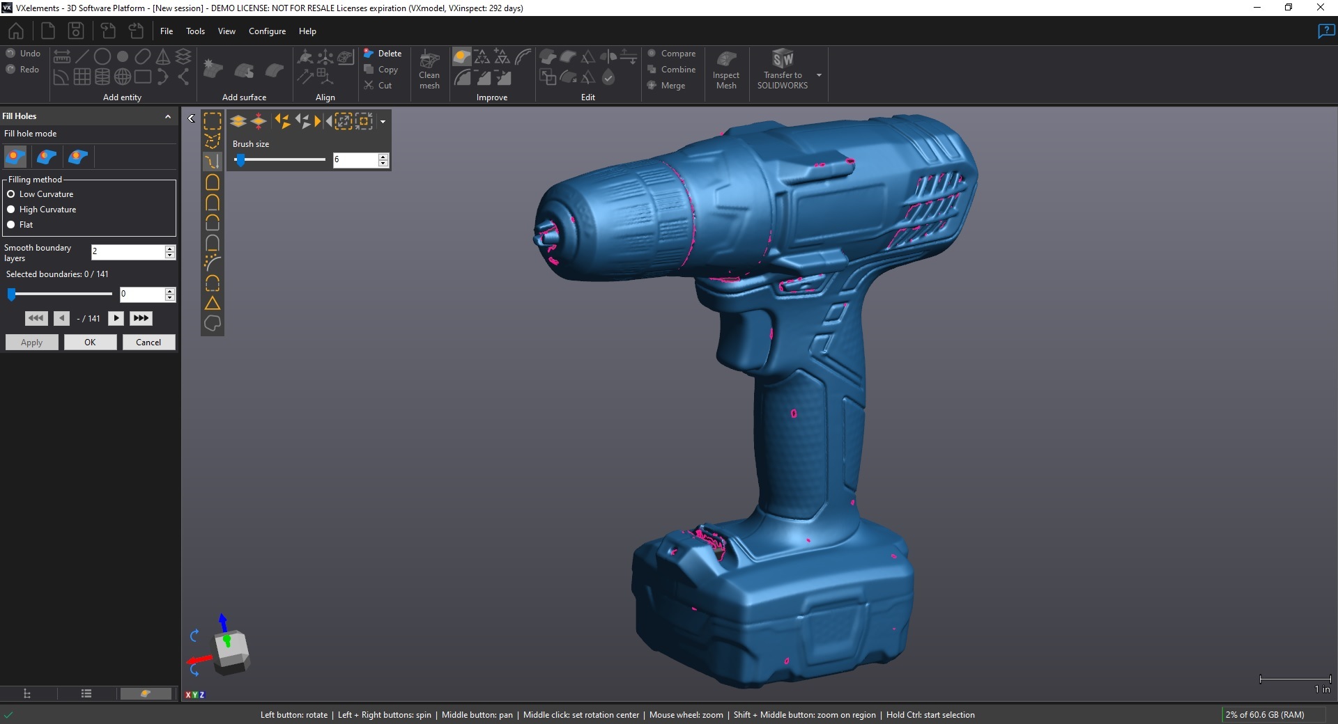
Improve the overall quality of your 3D scans. Fill holes with accuracy using curvature or flatness settings. A grab bar allows you to fill holes one by one, or you can attempt to fill all of them at once. You can choose to fill a hole entirely or select portions of it. Bridges allow you to create less complicated holes and help with fill accuracy. Reduce or increase your triangle count to improve quality. You can also smooth out any imperfections in the mesh.
Mesh Editing
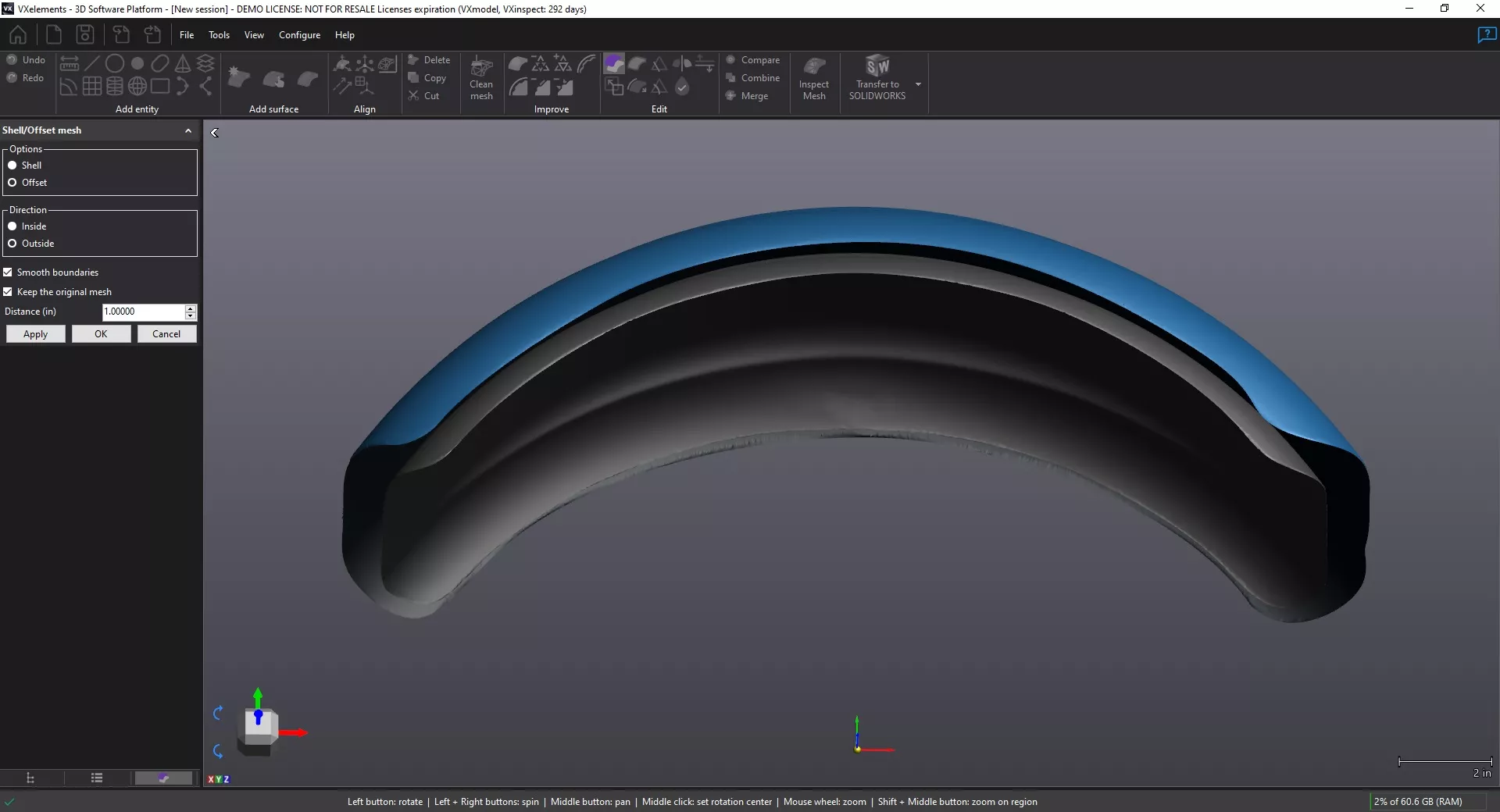
Modify several aspects of your scan data. You can scale a mesh to create mock-ups. The offset tool allows you to offset a mesh in two directions. Create volume for a mesh using the shell feature. You can extend or extrude a boundary for various operations. You can cut the mesh into several sections using planes or curves. Using the mirror tool, you can create an opposite side for your mesh. This can eliminate the need for multiple scans if parts are symmetrical.
Frequently Asked Questions
19 major 3D scan formats including STL, IGES, and OBJ.
Version 2015 or later. However, it is always recommended to have the latest version.
The software is designed to obtain reference geometry that needs to be imported into CAD for modeling.
Using the compare tool you can obtain a color map to show deviations between meshes. This can even be done with a solid body.
SCAN-TO-CAD Features
Clean Mesh
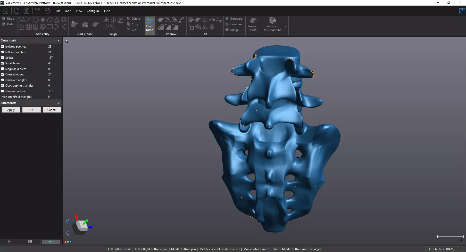
Clean up your scan data and get it prepared for auto-surfacing or reverse engineering. This feature runs multiple operations that help you fix the issues in your mesh. This includes isolated patches, self-intersections, spikes, creased edges and many more. Any problems that are found are highlighted in red. Check boxes allow you to decide which operations to run. The parameters section gives the user control over how to fix certain issues in the mesh. A preview button is available to make sure the mesh has been repaired.
Watertight Remesh
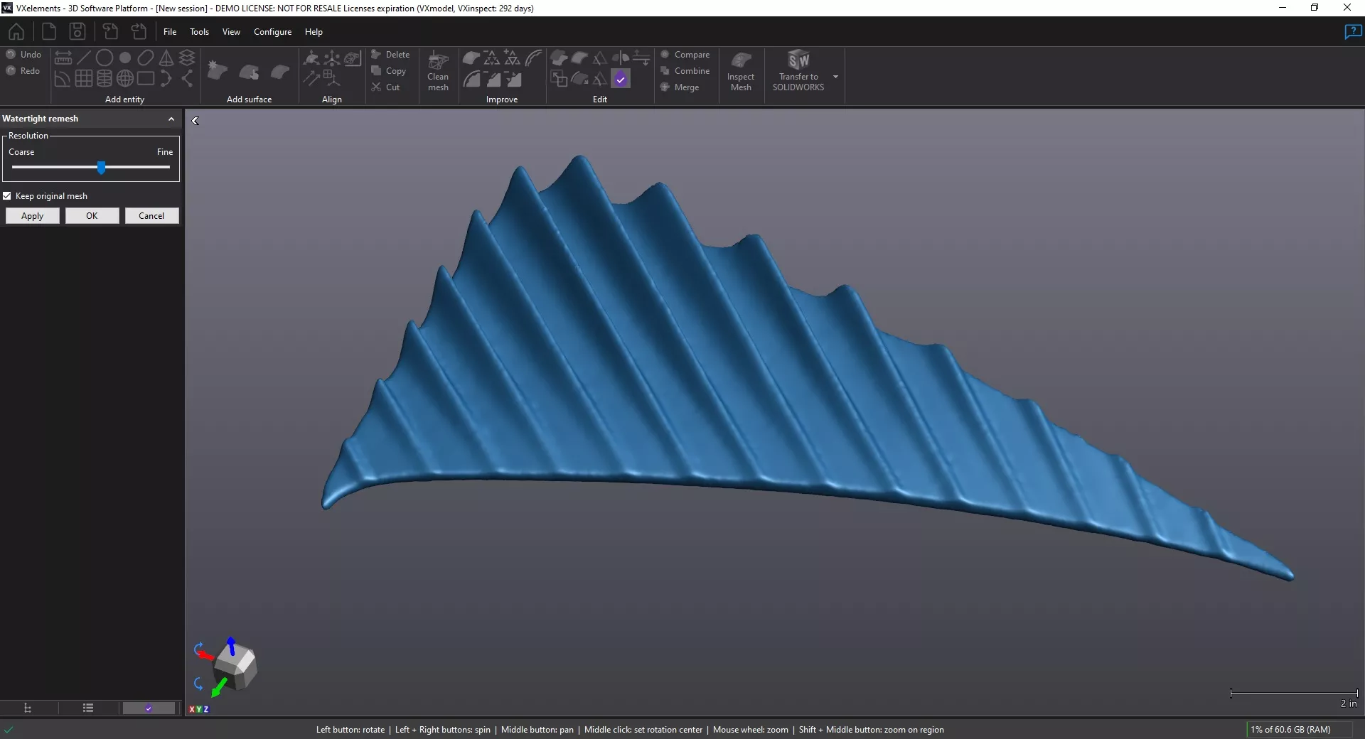
Create a water-tight mesh for 3D printing. In order to successfully print 3D scan data a mesh must completely watertight. This simply means the mesh cannot contain any holes. This tool will remesh all the scan data and fill holes automatically. The software uses the data around holes to determine whether it should be filled flat or with curvature. A grab bar allows you to increase or decrease the resolution of the results. Just in case you do not want to modify your original mesh, there is a check box to keep the original.
Boundary Editing
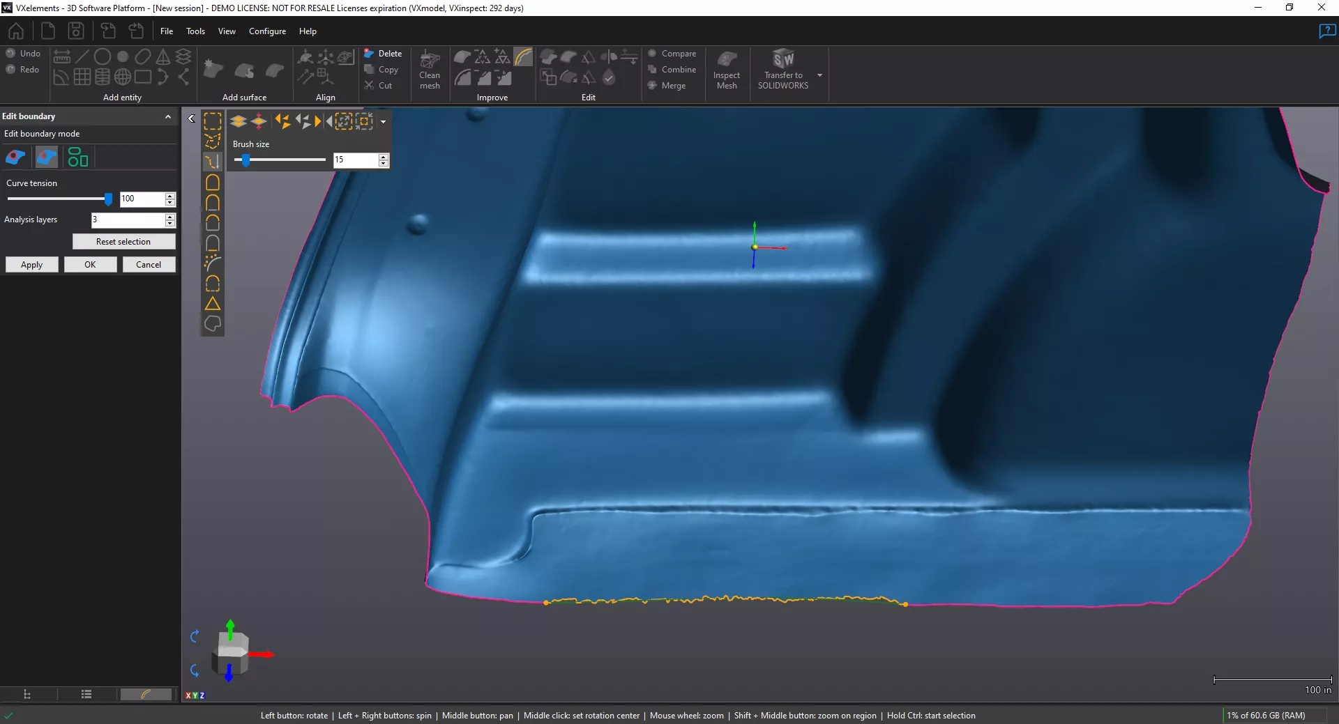
Smooth out the boundaries in your mesh. 3D scans that don’t have any volume, usually have jagged edges. This tool allows you to modify boundaries by using a curve tension. A grab bar allows you increase or decrease the curve tension to achieve the desired results. You can smooth an entire boundary or use the partial option. Circles, rectangles, and slots can also be fit onto boundaries. This is great for boundaries that appear to be prismatic but are not quite perfect.
SOLIDWORKS Cross Sections
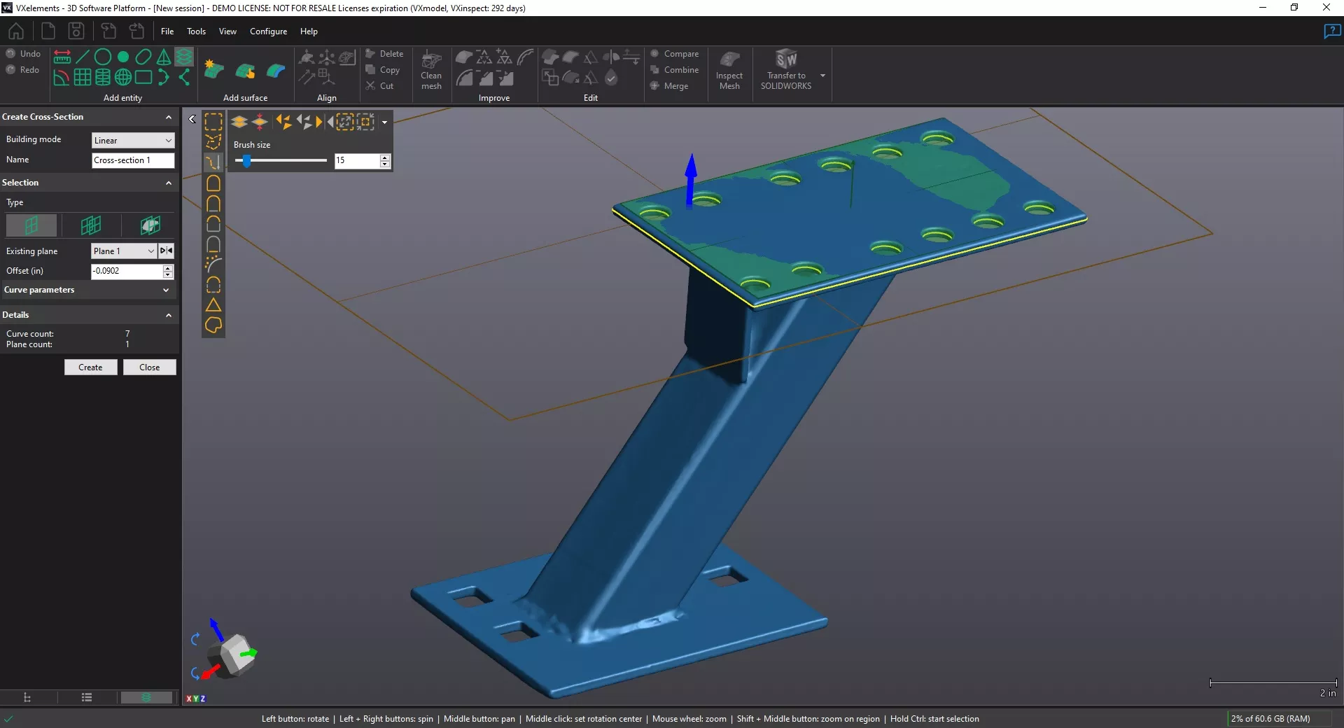
Generate 2D cross sections for reverse engineering. Use standard planes to intersect the mesh or create your own. Building modes include linear or radial cross sections. The silhouette option allows you to project data from multiple areas of the mesh. Create a single or multi-plane cross section. Choose a specific offset value or use the grab arrow to specify location. Transfer your cross sections to SOLIDWORKS and use them as a guide to create a parametric CAD model.
Auto Surface
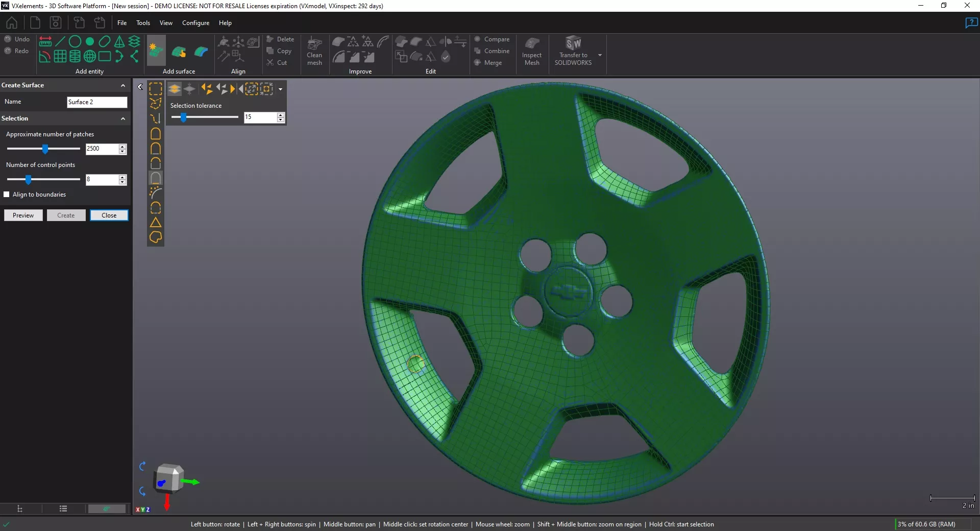
Create NURBS surfaces from 3D scan data. The auto-surfacing tool generates a patch network of knit surfaces around your mesh. The manual surface tool allows you to create your own patch network for custom results. Values can be typed in for approximate number of patches or number of control points. If you only need a surface for part of the mesh, you can use the selection tools. You can also choose to align to a surface to open boundaries for greater accuracy.
Additional Resources
Take Advantage of GoEngineer’s Extensive Knowledge Base and Resources

Find a Solution
Our robust Knowledge Base contains over 12,000 resources to help answer your product design questions. From basic CAD questions to in-depth guides and tutorials, find your solution here. Find a Solution

PROFESSIONAL TRAINING
Improve your skills with professional training and certifications in SOLIDWORKS, CAM, 3D Printing, and 3D Scanning offered four ways: self-paced, online, on-site, or in-classroom. Certified Training Courses

BLOG
#1 Technical Resource Worldwide - Right at your fingertips. Search or browse through hundreds of SOLIDWORKS tips & tricks, additive manufacturing product developments, announcements, how-to guides, and tutorials. Blog

YouTube Channel
Our YouTube channel hosts hundreds of educational tutorials, product demonstrations, recorded webinars, and best practices for all of our products and services. GoEngineer's YouTube Channel
ONLINE STORE
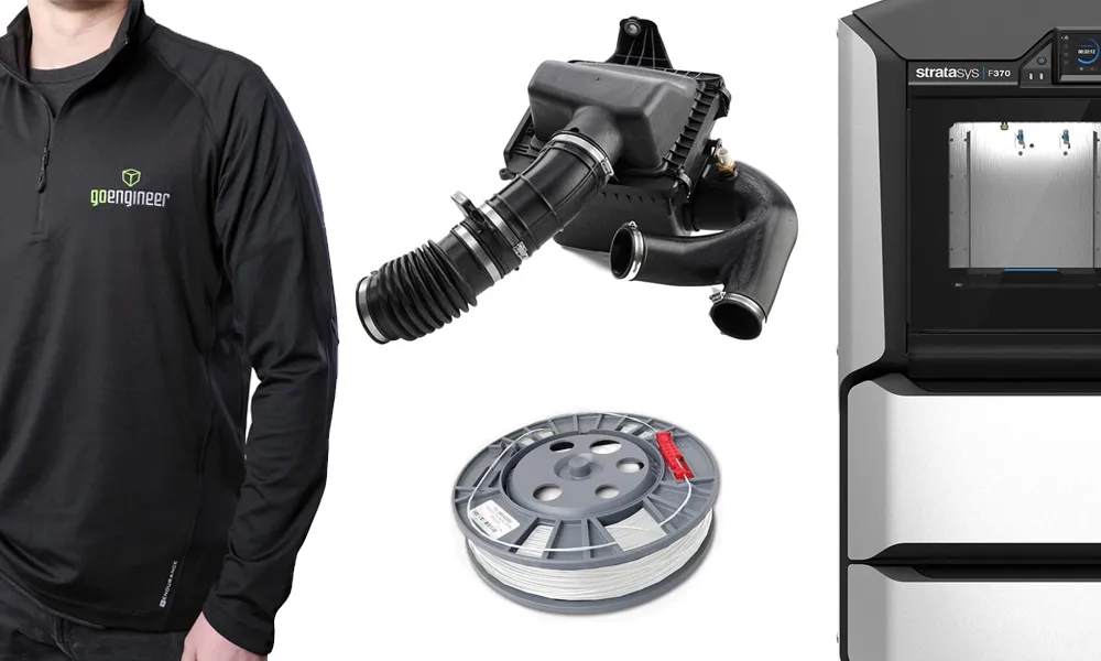
Order 3D printing materials and consumables, enroll in SOLIDWORKS training classes, and buy official GoEngineer gear directly from our online store. Online Store
WEBINARS
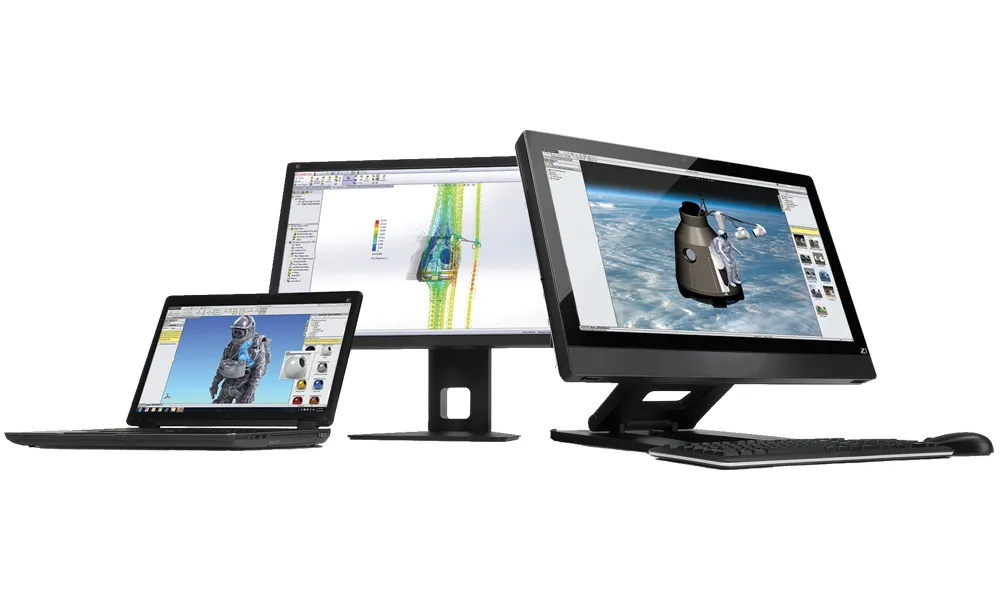
Our engineering webinars are hosted by some of the top experts in the industry. They are always recorded, always free, and always offer a live Q&A. WEBINARS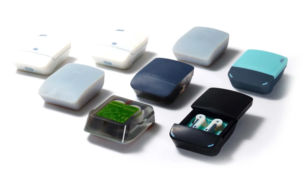
3D Printing Services
Need to 3D print a part? Our Additive Manufacturing experts will 3D print your part and deliver it to you using the latest technology on one of our professional FDM, PolyJet and SL 3D printers. 3D Printing Services