Geomagic Wrap
The fastest scan to CAD process available
What is Geomagic Wrap?
Geomagic Wrap is a reverse engineering software designed to be the fastest path for the scan to CAD process. Import 3D scan data and create solid bodies/surfaces with minimal steps. Features can be exported in a variety of formats to be used in SOLIDWORKS. With a user-friendly interface, the software can create clean and manifold mesh data for 3D printing. Wrap also has the ability to modify 3D scans that have texture and color.
Tools
GEOMAGIC Wrap
Acclerate your Scan to CAD process with advanced tool & capabilities.
3D Scan Data Preparation
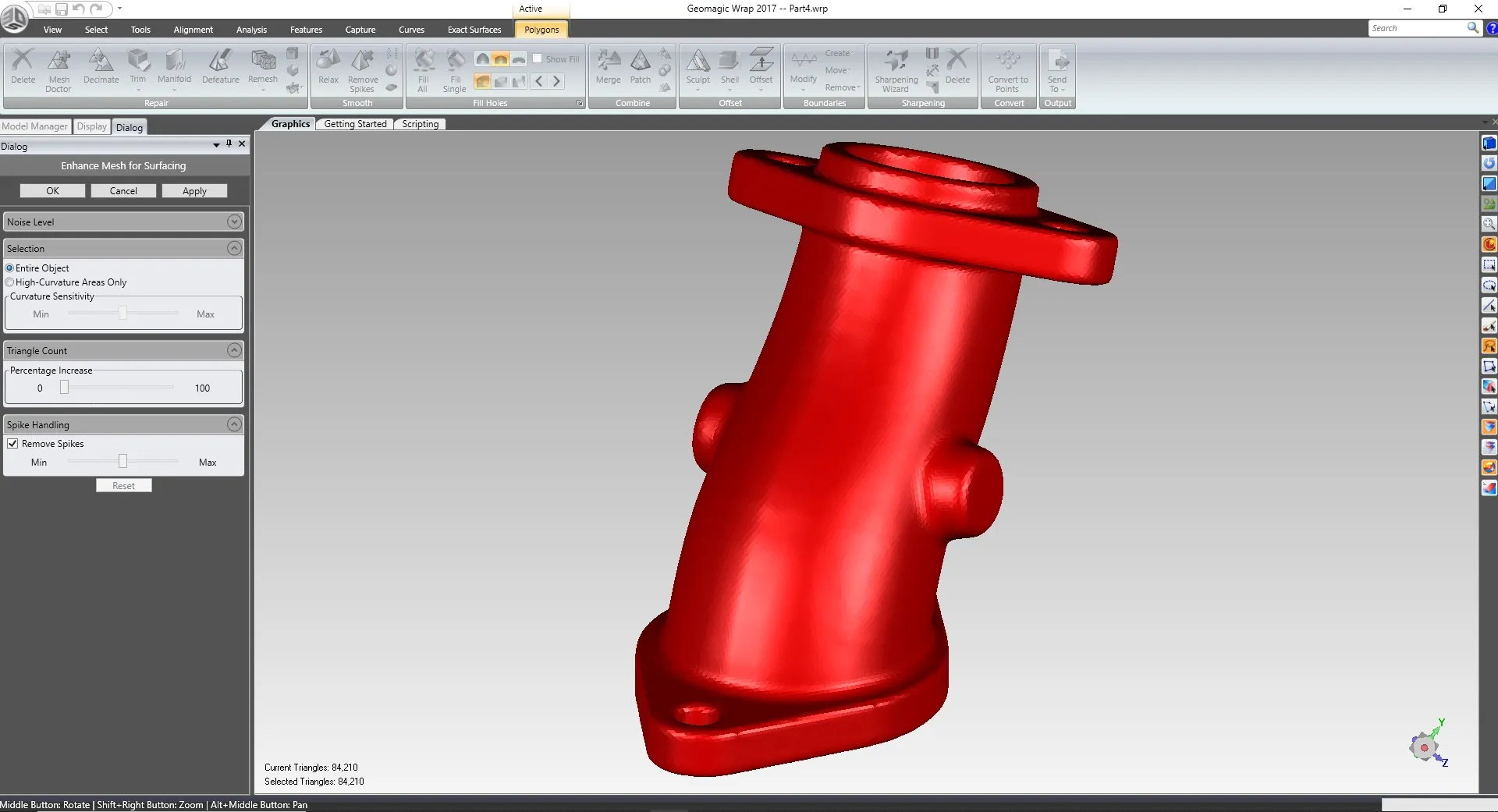
Create clean and manifold scan data using a variety of repair tools. Merge multiple scans together to create a single mesh. Fill holes using multiple curvature options. Create a watertight mesh ready for 3D printing. Optimize the triangle count to improve mesh quality for surfacing.
Scan Data Alignment
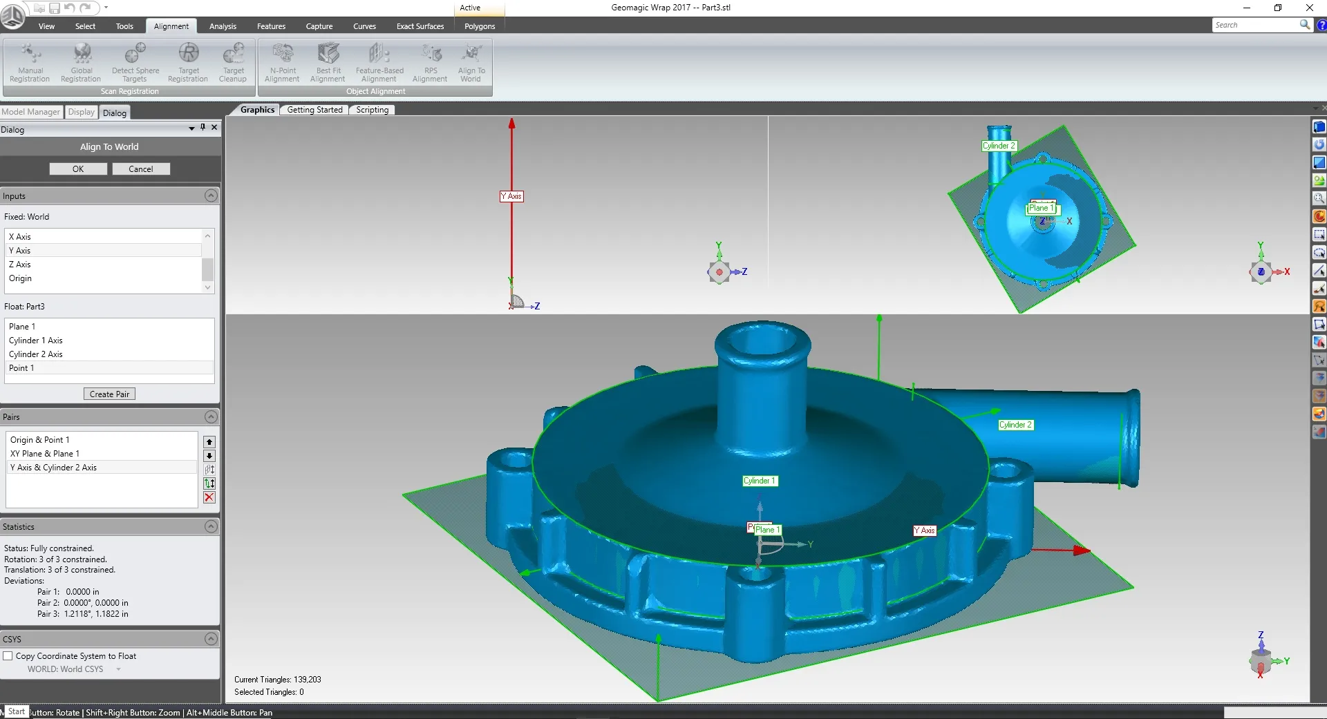
Align scans to the origin using reference geometry. Create planes, axis, cylinders, and many other entities directly from the scan data. XYZ planes correspond to actual CAD planes in SolidWorks. A split screen and preview are displayed to make sure the desired alignment is achieved before accepting.
2D Sketching
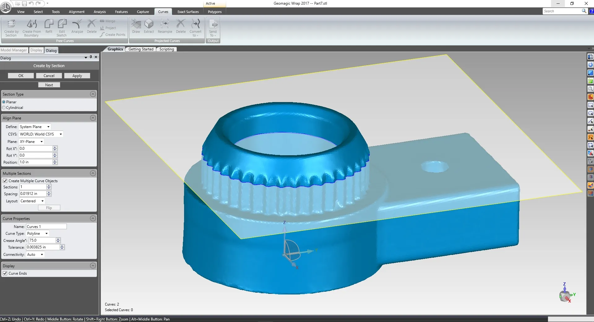
Use reference planes to create 2D cross sections. These sketches can be imported into SOLIDWORKS for reverse engineering. Curve options include splines, lines/arcs, and polylines. Choose the distance, angle and tension of the curve entities. Open ends in a curve can be displayed and closed.
Exact Surfacing
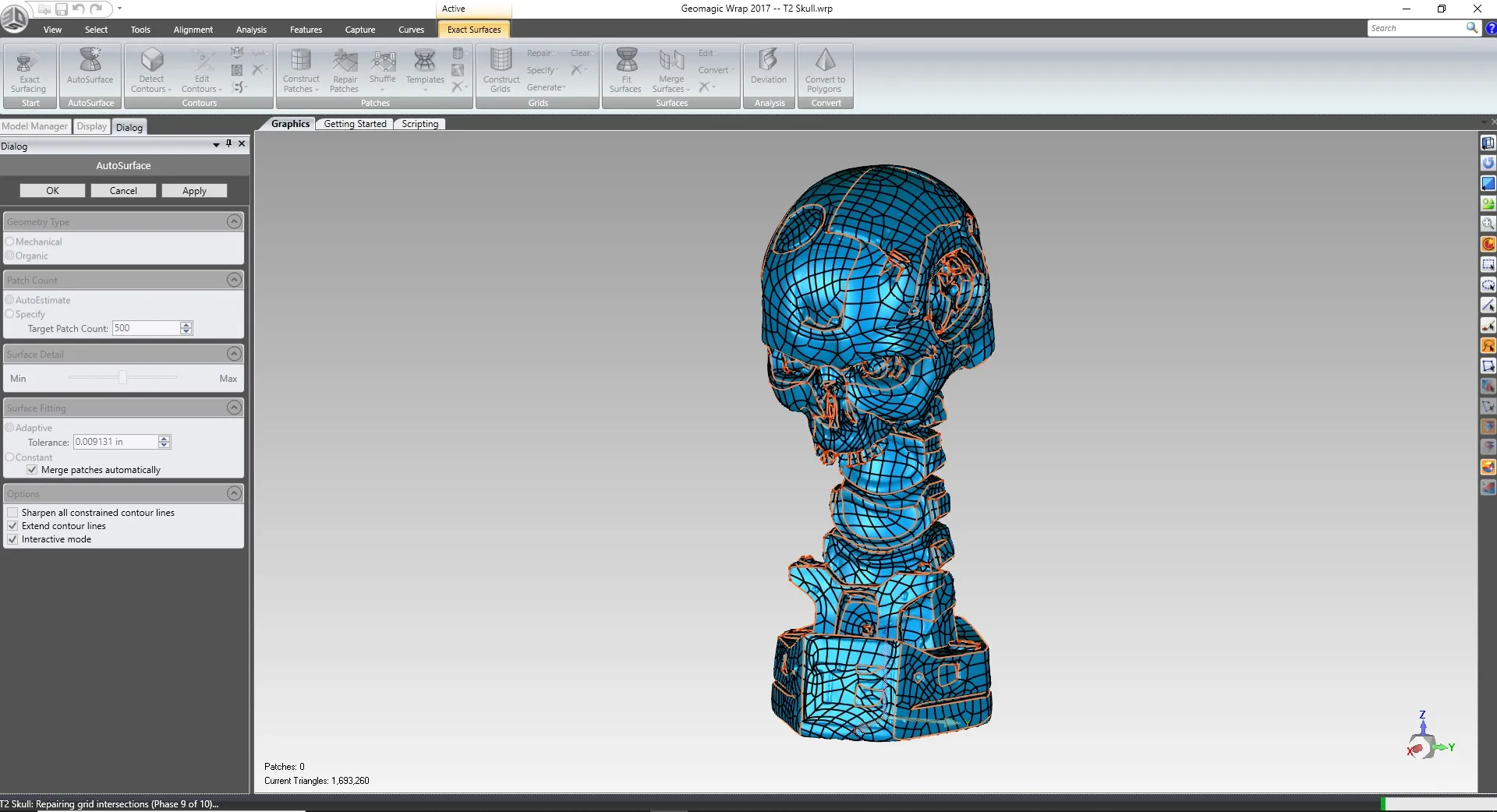
Create accurate surfaces and/or solid bodies using scan data as a reference. This process involves the creation of a patch network of knit surfaces. If the mesh is watertight a solid body will be created. Mesh data with no volume will create surface bodies. The exact surfacing module allows for manual or automatic patch network generation.
Frequently Asked Questions
Over 60 file formats including: STL, OBJ, PLY, and various texture formats.
STEP, IGES, X_T, and other universal CAD formats.
.You can measure between points or features such as planes.
You can merge, combine, patch, or align meshes to each other.
GEOMAGIC Wrap Features
Mesh Doctor
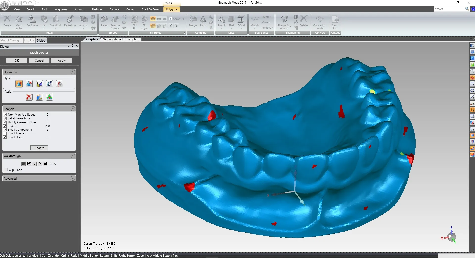
Locate and fix problem areas in your scan data quickly and effectively. The mesh doctor runs a series of tests to locate various types of imperfections. You can select “auto-repair” and the software will try to fix everything for you. If you prefer to fix issues manually there is a “walkthrough” section. This allows you to go through every issue and fix it one by one. Mesh doctor tools include hole filling, spike-edge removal, and defeature. Using a variety of selection tools, you can pick and choose exactly what you want to modify.
Texture Modification
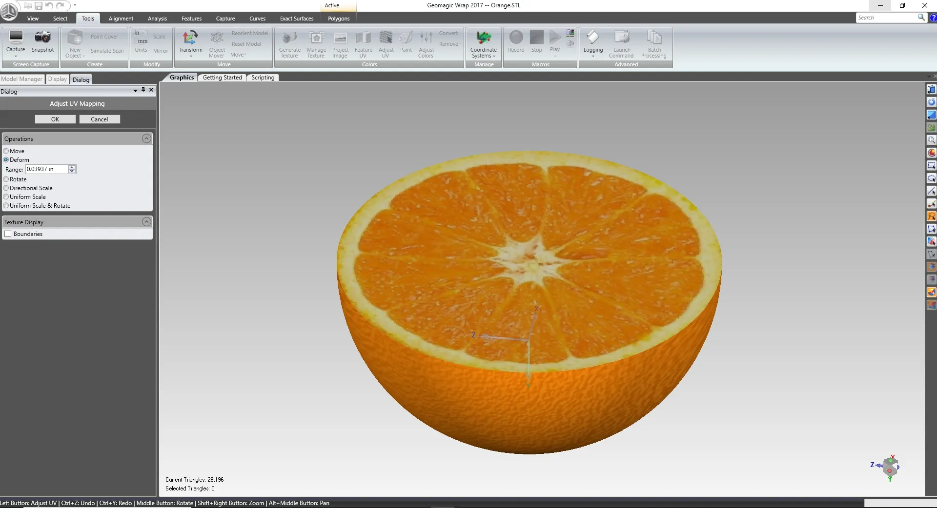
Modify the texture map of color 3D scans. You can move, deform, rotate, and scale texture. Color adjustment settings allow you to control the contrast or brightness. UV map editing tools allow you to verify the texture fitment. Project/wrap an image onto a 3D scan. Paint settings are available for manual color modifications. Generate and export modified texture files for use in other software or 3D printing.
Engrave
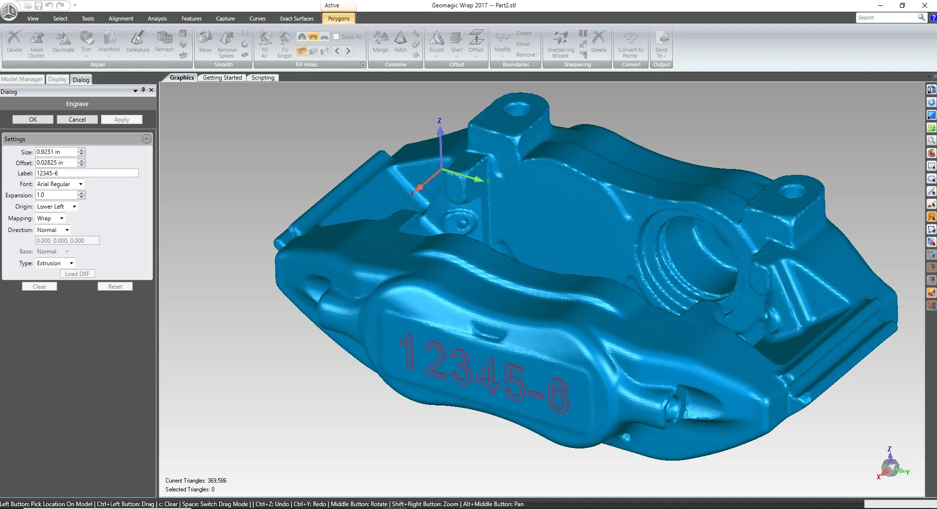
Create raised or inset lettering on your mesh. This is great for part numbers. Project the lettering onto the mesh or have it wrap around curved areas. Choose from a variety of fonts to achieve the desired look. Modify the size and spacing of your text. You can even import a DXF file to engrave a company logo. Lettering is extruded clean and straight.
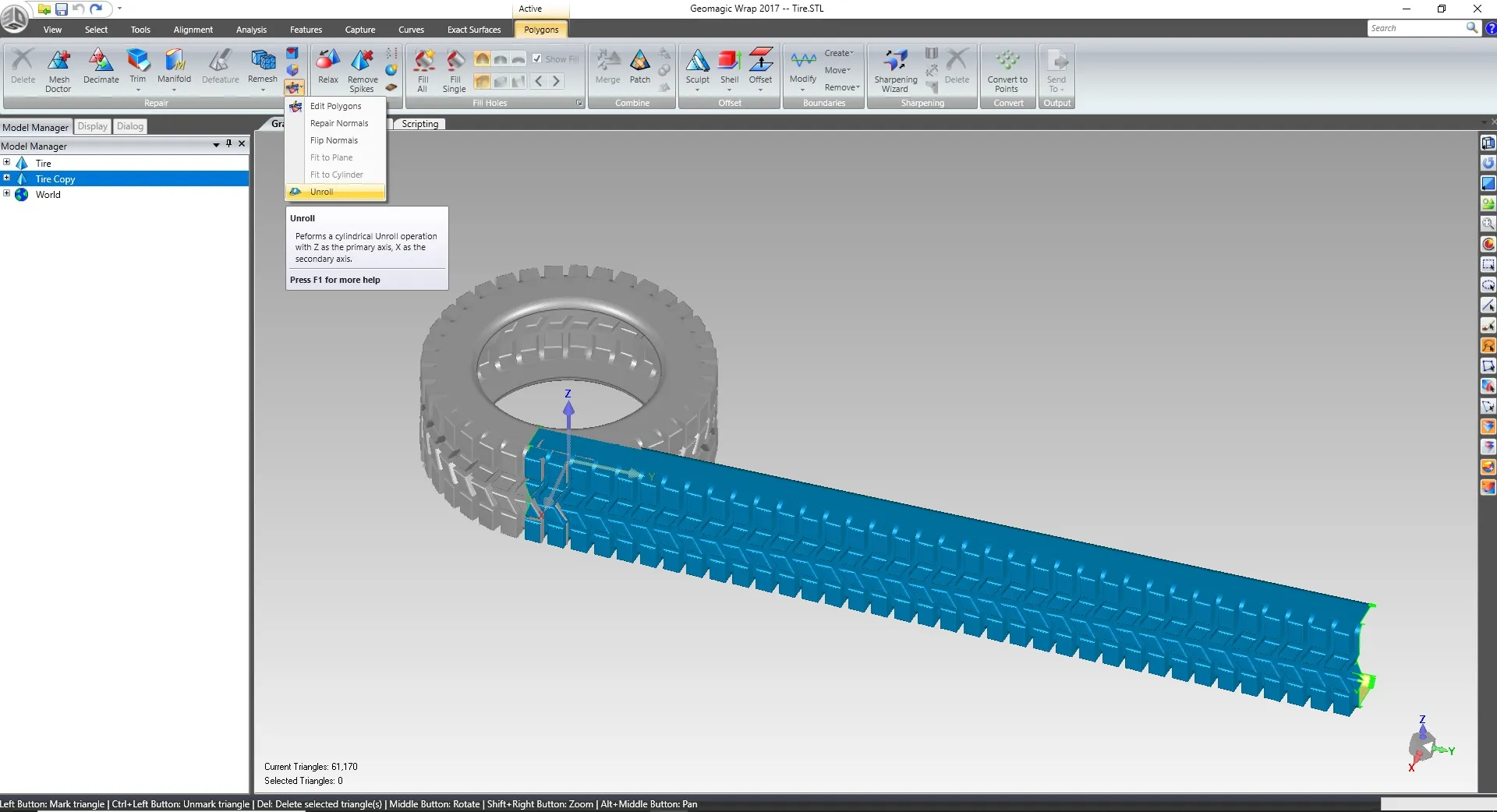
Unroll
Unroll cylindrical meshes to get a better look at pattern geometry. You can use this tool to capture more accurate cross sections for reverse engineering. A mesh is unrolled using the world XYZ axis. All you have to do is align the cylinder portion of the mesh normal to the Z axis. With a click of a button the software creates a flat pattern of the cylindrical mesh.
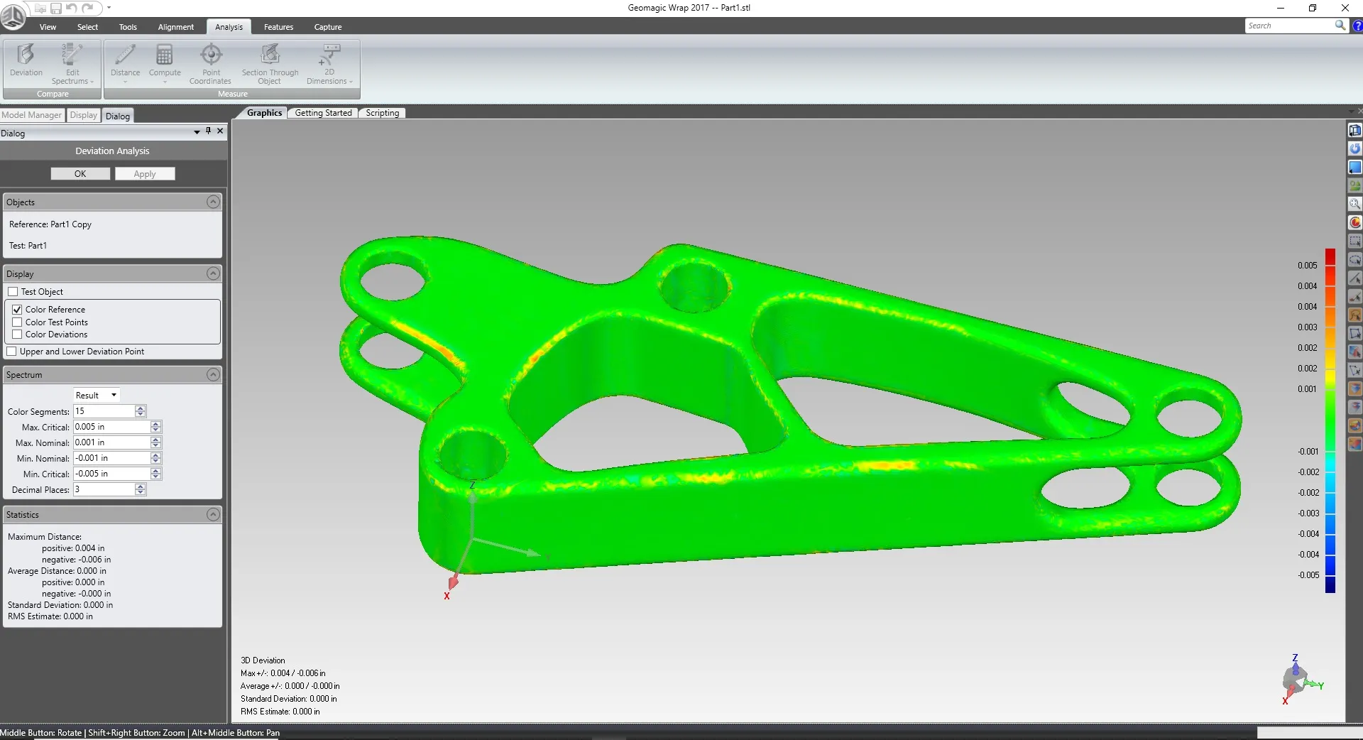
Deviation
Check the accuracy of your CAD features using the deviation tool. After you create auto-surface bodies, it is always important to check how close they are to the original mesh. The software creates a color map to show the areas that are either high or low in comparison to the mesh. This will help you spot areas that need to be modified during the auto-surface process.

Additional Resources
Take Advantage of GoEngineer’s Extensive Knowledge Base and Resources

Find a Solution
Our robust Knowledge Base contains over 12,000 resources to help answer your product design questions. From basic CAD questions to in-depth guides and tutorials, find your solution here. Find a Solution

PROFESSIONAL TRAINING
Improve your skills with professional training and certifications in SOLIDWORKS, CAM, 3D Printing, and 3D Scanning offered four ways: self-paced, online, on-site, or in-classroom. Certified Training Courses

BLOG
#1 Technical Resource Worldwide - Right at your fingertips. Search or browse through hundreds of SOLIDWORKS tips & tricks, additive manufacturing product developments, announcements, how-to guides, and tutorials. Blog
YouTube Channel
Our YouTube channel hosts hundreds of educational tutorials, product demonstrations, recorded webinars, and best practices for all of our products and services. GoEngineer's YouTube Channel
ONLINE STORE
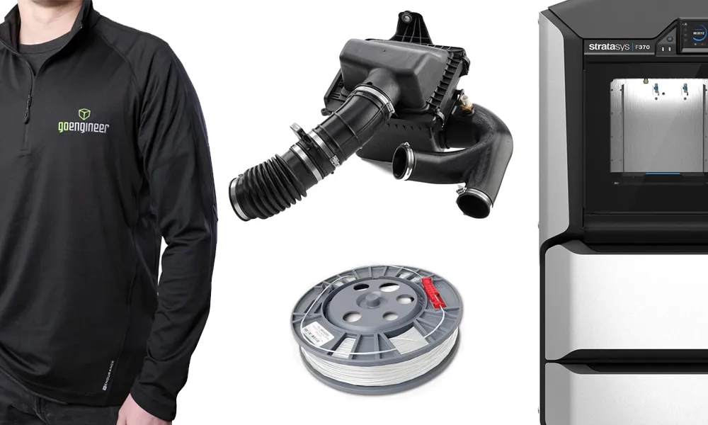
Order 3D printing materials and consumables, enroll in SOLIDWORKS training classes, and buy official GoEngineer gear directly from our online store. Online Store
WEBINARS
Our engineering webinars are hosted by some of the top experts in the industry. They are always recorded, always free, and always offer a live Q&A. WEBINARS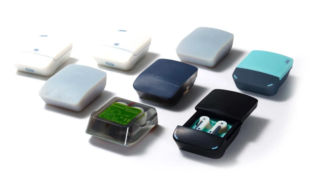
3D Printing Services
Need to 3D print a part? Our Additive Manufacturing experts will 3D print your part and deliver it to you using the latest technology on one of our professional FDM, PolyJet and SL 3D printers. 3D Printing Services