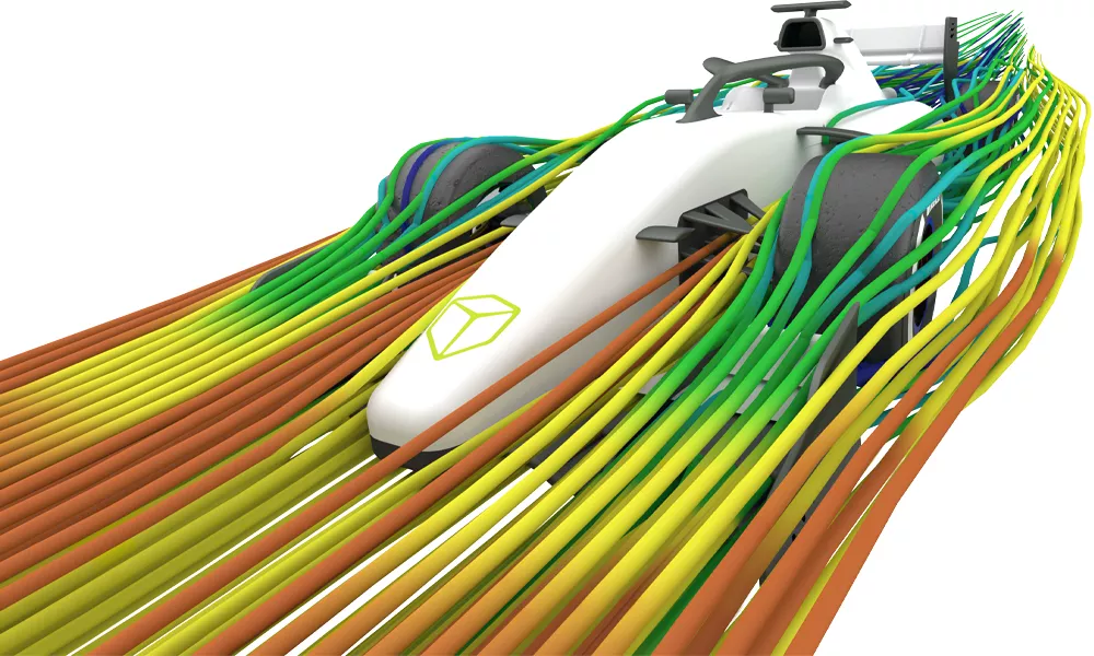
SOLIDWORKS Simulation
Finite Element Analysis (FEA) Software
What is Simulation?
SOLIDWORKS Simulation is a Finite Element Analysis (FEA) program built into the familiar SOLIDWORKS CAD interface. Simulation provides designers and engineers the tools they need to quickly test their designs and intelligently iterate on them. Utilizing NAFEMS validated FEA solvers, SOLIDWORKS Simulation can provide accurate, reliable results for a wide range of study types from basic linear static analysis to more complex nonlinear and dynamic analysis. Speed up the iteration and prototyping phase of your design process with SOLIDWORKS Simulation.
How accurate are the results?
A ccuracy and reliability is a common question of all Simulation tools. How do we know the results can be trusted? Fortunately, there is an independent group that handles this. The National Agency for Finite Element Methods and Standards (NAFEMS) tests simulation programs against benchmark studies with known results that have been validated mathematically and empirically. All study types available in SOLIDWORKS Simulation have been tested and validated by NAFEMS.
Still not convinced? SOLIDWORKS has included setup guides and the NAFEMS benchmark models in the Simulation software so users can run the analysis and compare the results themselves.
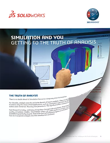
Simulation and You: Getting to the Truth of Analysis
While simulation has expanded beyond being an exclusive tool for analysts, many companies continue question whether analysis is an effective tool for their business. This paper will address these questions, including:
- How accurate do analyses need to be?
- Should they always be as precise as possible?
- What effect does simulation have on prototyping? Does it eliminate it? Lower it?
- Do analysis results take the place of experience in decision-making?
- Where else in development can simulation be used? Is it only verification and validation?
The role of analysis in development has changed and expanded. There are whole new parts of the development process where it can provide value. Download the whitepaper to learn more.
Tools
SOLIDWORKS SIMULATION
Analysis tools designed to optimize your testing.
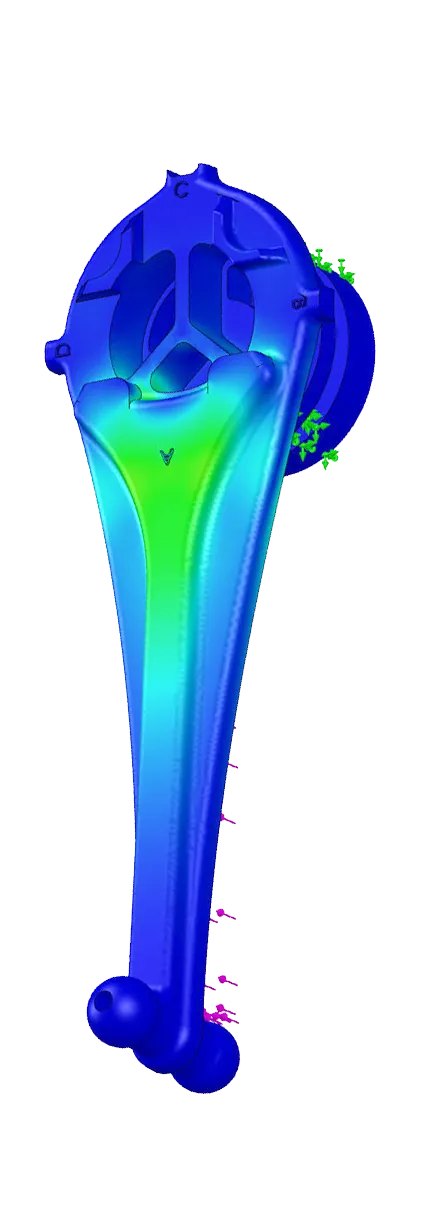
Linear Static Analysis
Test designs using linear materials under steady-state load conditions to quickly analyze and iterate designs based on stress, strain, displacement, and Factor of Safety (FOS) results. The included Trend Tracker tool helps engineers to track the results of design changes automatically.
Motion (Kinematic) Analysis
Leverages user-defined constraints (mates) in assemblies and mechanical inputs (gravity, springs, dampers, forces, etc.) to accurately recreate the mechanical movement of the assembly and provide designers with reaction forces, position, acceleration, and velocities.
Fatigue Analysis
Used to test the life of designs due to fatigue failure, engineers can apply multiple load scenarios including varying and cyclic loads where peak stress is below material yield to understand the expected life-span of their designs.
Frequency Analysis
Also known as modal analysis, this test is used to determine both the modal shape and natural frequencies of both parts and assemblies. This is critical information for an Engineer to have when creating designs that will be subjected to vibration inputs or used in vibrating environments.
Thermal Analysis
This test gives engineers a method to study and understand the heat transfer, both steady-state and transient, through conduction between components as well as both radiation and convection into the surrounding environment. The results of this analysis can be used in a stress analysis to see how the thermal conditions will affect the stress and displacement in a part or assembly.
Topology Optimization
Rather than creating a design and validating it, this study allows engineers to specify the “bounding box”, stiffness, weight and frequency requirements of the component and allow the software to generate the ideal shape to meet those requirements while considering manufacturing constraints.
Parametric Optimization
Allows designers to rapidly test and optimize a design based on variables such as dimensions, and materials with given constraints and overall goals such as weight, strength, frequency, and even manufacturing cost.
Buckling Analysis
Used to analyze load-bearing structures that are placed under compressive forces to accurately test the Factor of Safety (FOS) against buckling failure of a design.
Drop Test
Provides an easy to use tool for simulating drop test impacts of components and assemblies. Drop test analysis gives full control on the impact surface, height, velocity, and angle of the drop to understand how a design will behave when subjected to a drop impact.
Nonlinear Analysis
Rubbers, plastics, Nitinol, and other nonlinear materials cannot be accurately tested with a linear solver. Nonlinear analysis allows engineers to use advanced material models to accurately analyze designs that incorporate these materials.
Composite Analysis
Used when designing with materials such as fiberglass or carbon fiber, this study allows engineers to specify fiber orientation and layup schedule for their designs. The results provide information on stresses at each layer as well as interlaminar stresses and composite specific results like Tsai Hill and Tsai Wu.
Dynamic Analysis
Allows designers to test Modal Time History, Harmonic Analysis, Random Vibration, and Response Spectrum of components and assemblies. Results such as transient response, peak response, stress, acceleration, and displacement can be provided by this type of analysis.
Simulation Packages
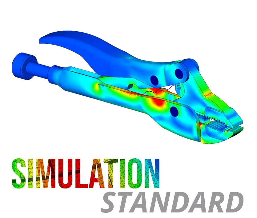
SOLIDWORKS Simulation Standard allows users to use connections such as bolts and pins to stress test their assemblies, simulate realistic assembly motion, and calculate joint forces.
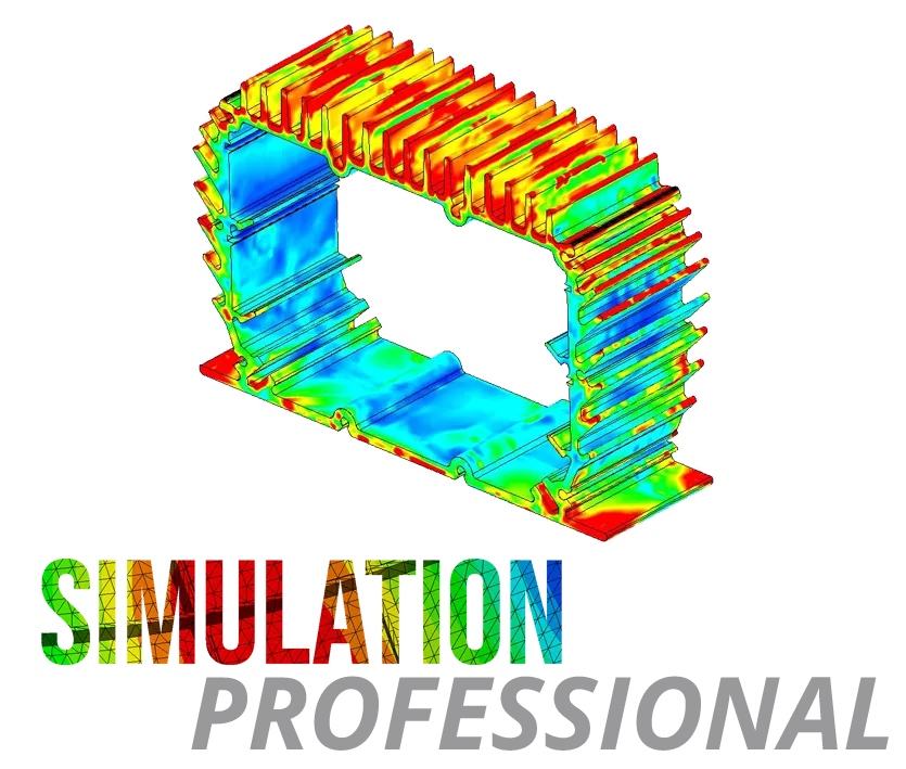
SOLIDWORKS Simulation Professional offers a comprehensive toolset for improved assembly simulation. Functionality includes calculation of modal vibration, transient thermal temperature loading, DoE and topology optimization, and more!
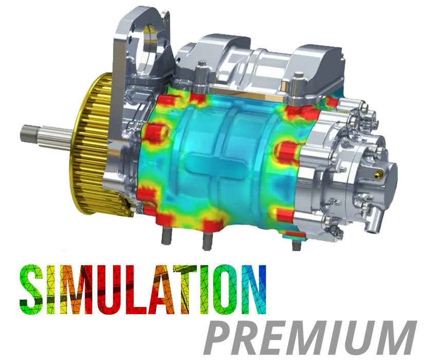
SOLIDWORKS Simulation Premium allows users to perform high-level non-linear simulations for exotic materials, complex load cases, and large deformation problems. Simulate advanced vibration for harmonic, random vibration, and shock loading.
Compare SIMULATION Packages
Standard
Professional
Premium
Fully Embedded Analysis
SOLIDWORKS Simulation is a fully integrated Finite Element Analysis solver that users can leverage to test the strengths of their design. Boasting 3 tiers of capabilities, users have a wide variety of modules to ensure the performance of their designs under static, dynamic and thermal loading.
Linear Static Analysis
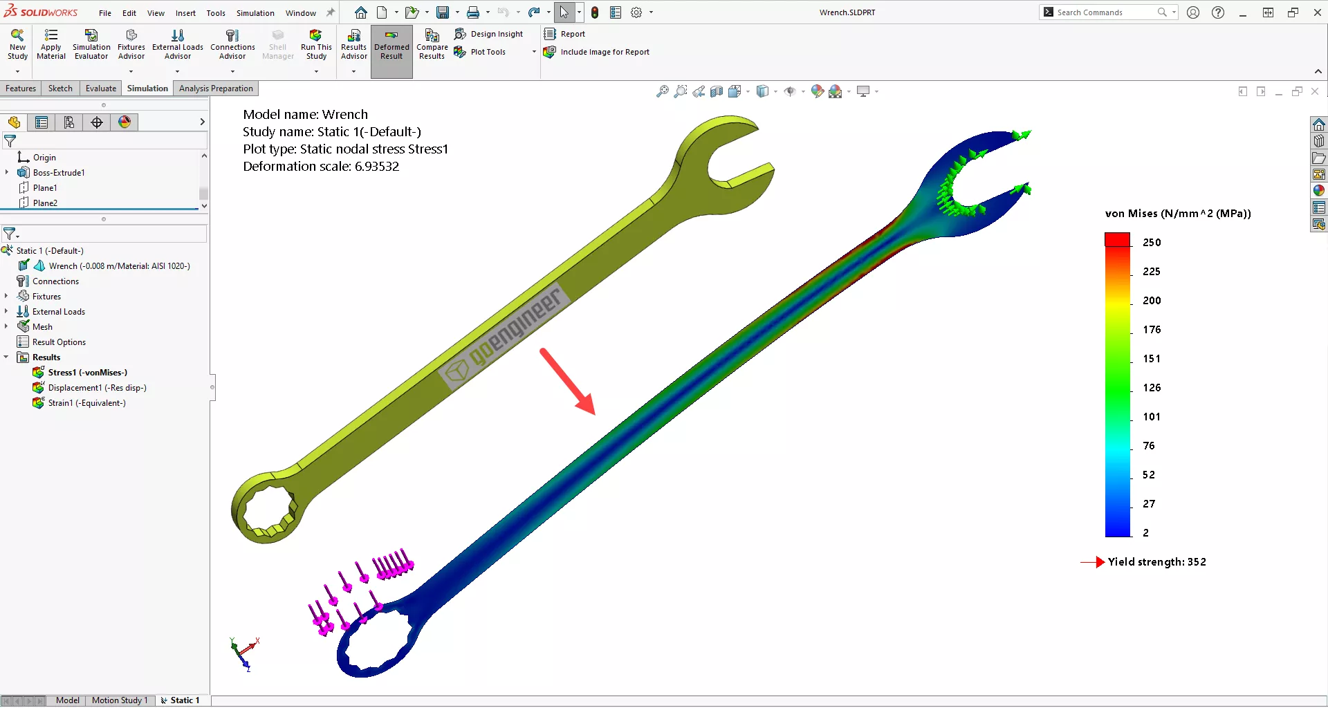
This fully functional, integrated FEA tool allows users to easily make critical design decisions reducing the time and money spent on prototyping and testing by finding stress, strain, displacement, and Factors of Safety on designs that are undergoing steady-state static load conditions.
Fatigue Studies
Allows users to easily simulate a design's life, damage, load factors, and peak stress locations from long-term repeated loading and unloading with stresses less than the material's yield stress. This fully integrated tool can simulate constant and variable amplitude loads with computer-generated random loads or historical load data using existing simulation studies.
Time-Based Motion Analysis
Using rigid body kinematics and the ADAMS (Automated Dynamic Analysis of Mechanical Systems) solver, a user can easily and accurately simulate the movement of bodies based on user-defined mates and mechanical inputs like gravity, forces, springs, and dampers. Results of this simulation method give the user data on positions, velocities, accelerations, and reaction forces.
Trend Tracker
This seamlessly integrated utility enables a designer to track the simulation results based on design changes made to a part or assembly. After a baseline model is defined, any changes in the study setup or geometry are recorded, and the tracked data graphs are updated to show how the results have changed.
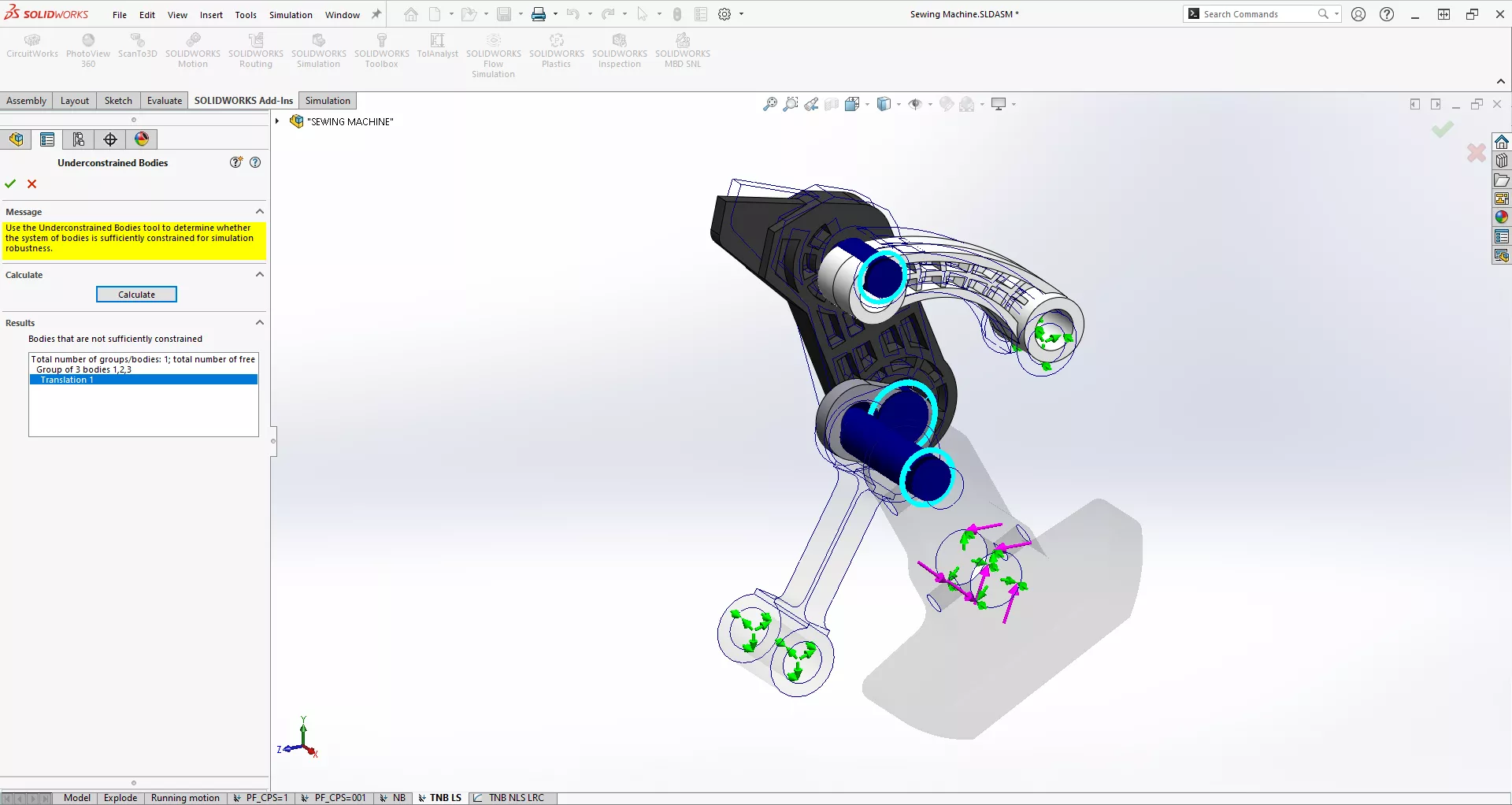
Detecting Unconstrained Bodies
This tool in SOLIDWORKS Simulation allows the user to quickly and easily show ridged body movements which are not allowed in SOLIDWORKS Simulation and to see exactly how the unconstrained bodies would move. This allows the user to visually see how to constrain the offending body to stabilize the analysis.
Event-Based Motion
Do you need to run a motion analysis on a complex system where you are unsure when a specific event will happen but when it does you need the system to respond in a specific way? If so, then Event-based Motion Analysis may be the right tool for you. This is a SOLIDWORKS Simulation Professional level tool that will allow you to set tasks that will activate when there is a triggering event. For example, a box with a known mass is moving along a conveyer belt and needs to change to a different direction at a specific point. You can set a mass sensor at that point which triggers an arm to push the box in a different direction along the conveyor belt when the correct weight is on it.
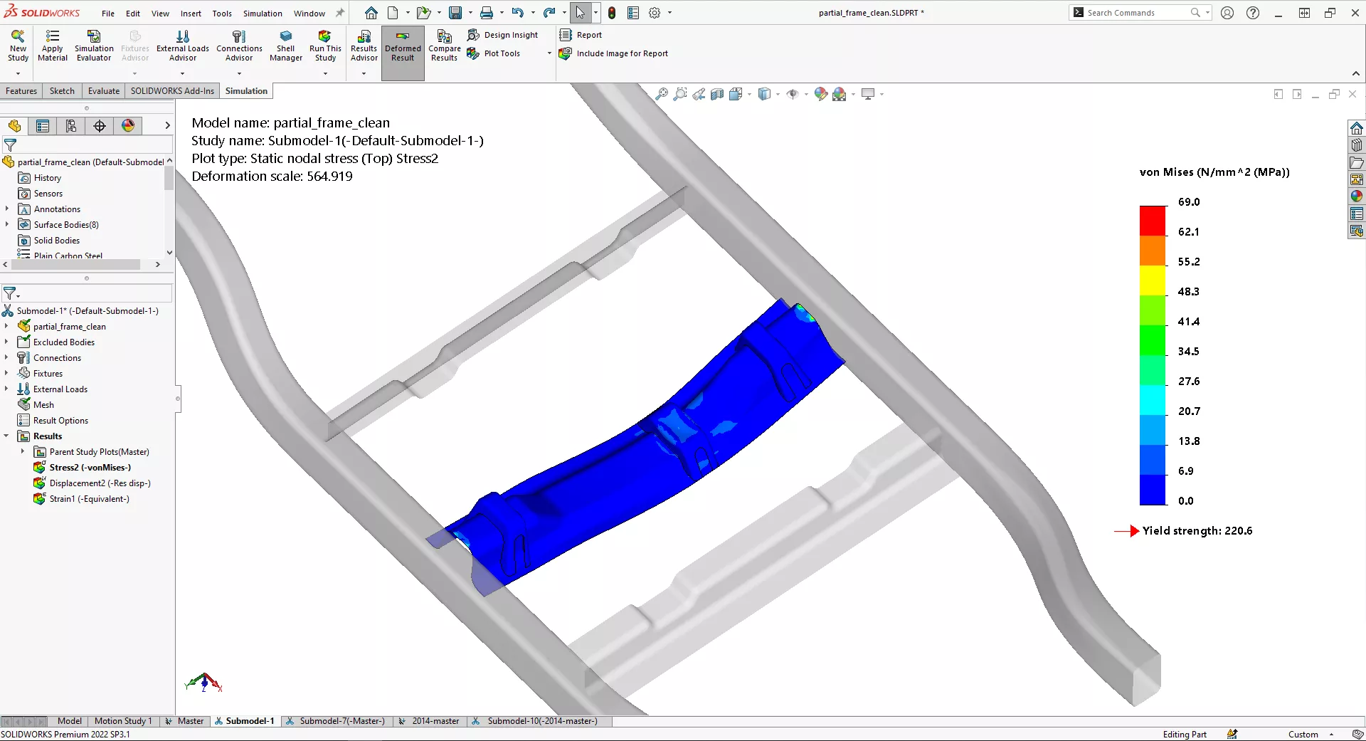
Submodeling
Increase the accuracy of a SOLIDWORKS Simulation study without drastically increasing the overall mesh density. The Submodeling option allows the simulation analyst to run a “parent” study at a low mesh density that does not take too long to solve. Focus in on a specific part in the “parent” study and mesh just that one part with a much denser mesh while the boundary conditions from the “parent” study applied to the part of interest remain constant. This tool can give you accuracy without causing meshing headaches.
2D Simplification
Save precious time and calculation resources with your Simulation Studies by using our 2D Simplification capabilities. If the model is symmetric or axis-symmetric and can be loaded with symmetric external loads, we can set up and run our models and studies by simply working with a single 2-Dimensional, planar representation of the original 3-Dimensional model. Results can still be shown with full 3-Dimensional detail.
Optimization
Marry your SOLIDWORKS dimensions to your structural simulations with this DOE-based optimization. The Box-Behnken experimental design method gives you confidence that you’ve found the best design. A typical objective is to minimize the mass of your design to reduce material costs while making sure your design still meets standard Factor of Safety constraints to ensure your light-weighted design is robust.
Thermal Analysis
Understand the thermal performance of your designs with the built-in thermal solver in SOLIDWORKS Simulation. Simulate conduction, radiation, and convection constraints through coefficients to rapidly determine the temperature distribution and heat fluxes in a design. These thermal results can be used to determine the thermal strains on a model as well.
Buckling Analysis
The linear buckling analysis module enables users to determine the critical buckling load, the compresive load required to buckle an object. This way, users are able to predict if their components fail due to yielding of the material or compliance of the structure.
Frequency Analysis
When designing objects that experience vibration, designers can easily find the natural frequencies and modal shapes of vibrating bodies, helping the designer modify designs to avoid harmonic resonance and damage from such cases. Also known as Modal Analysis, this fully integrated tool is critical for designers in many fields to create resilient parts and assemblies.
Drop Test Analysis
Take advantage of the explicit solver in SOLIDWORKS Simulation to test the strentgth of your designs when dropped from a certain height. With this program you have the ability to incorporate material plasticity to get accurate stresses in your models.
Pressure Vessel Analysis
Streamline pressure vessel analyses with Pressure Vessel Design Studies in SOLIDWORKS Simulation Professional. Included tools and workflow allows users to follow the ASME Boiler and Pressure Vessel Code so that they may investigate the five stress intensity limits as well as full result interrogation both qualitatively and quantitatively on all result plots.
Topology Study
Gain some insight on your design and increase its performance efficiency by exploring models with Topology studies. Set up a study with the required fixtures and loads and let the Topology Study explore the geometry volume of the model. The output is a proposed alternative design that will satisfy strict requirements. Optimization approaches include minimizing the mass, increasing overall model stiffness, or minimizing the maximum displacement.
Load Case Manager
Manage your simulation studies without cluttering the user interface with the Load Case Manager. Use this tool to run multiple load cases on a certain design, speeding up the meshing and analysis process. Users are able to combine the loading from multiple load cases and determine their cumulative effects on stesses, strains, and displacements of a design.
Nonlinear Analysis
If you are trying to run an analysis with high deformations, variable loading, or are operating in the nonlinear portion of a stress-strain curve, then SOLIDWORKS Nonlinear Analysis may be the right choice of simulation for you. Nonlinear analysis is for simulation use cases that vary over time, distance, or as a material model.
Plastic Deformation/Residual Stress
This is what happens to materials placed under such high force loads that after the force has been dropped or taken away, the material does not return to its original shape. Think of a paper clip that you pull too hard then let go of. That paper clip will never be the same shape again. It will always be just a little off center. SOLIDWORKS Nonlinear analysis can analyze models that have been stressed to the point of no return and give you results of how much stress the model sees during the force loading event as well as how much permanent deformation there will be in the model after the force load is released.
Composite Material Analysis
Fine-tune your composite layup with Composite Shells in SOLIDWORKS Simulation Premium. Composite shells can map to the natural UV curves of SOLIDWORKS surfaces. Fiber orientations and layer thicknesses can be adjusted on-the-fly or imported from a spreadsheet. Couple this with a DOE to find the best way to stack and orient your composite layers.
Dynamic Analysis
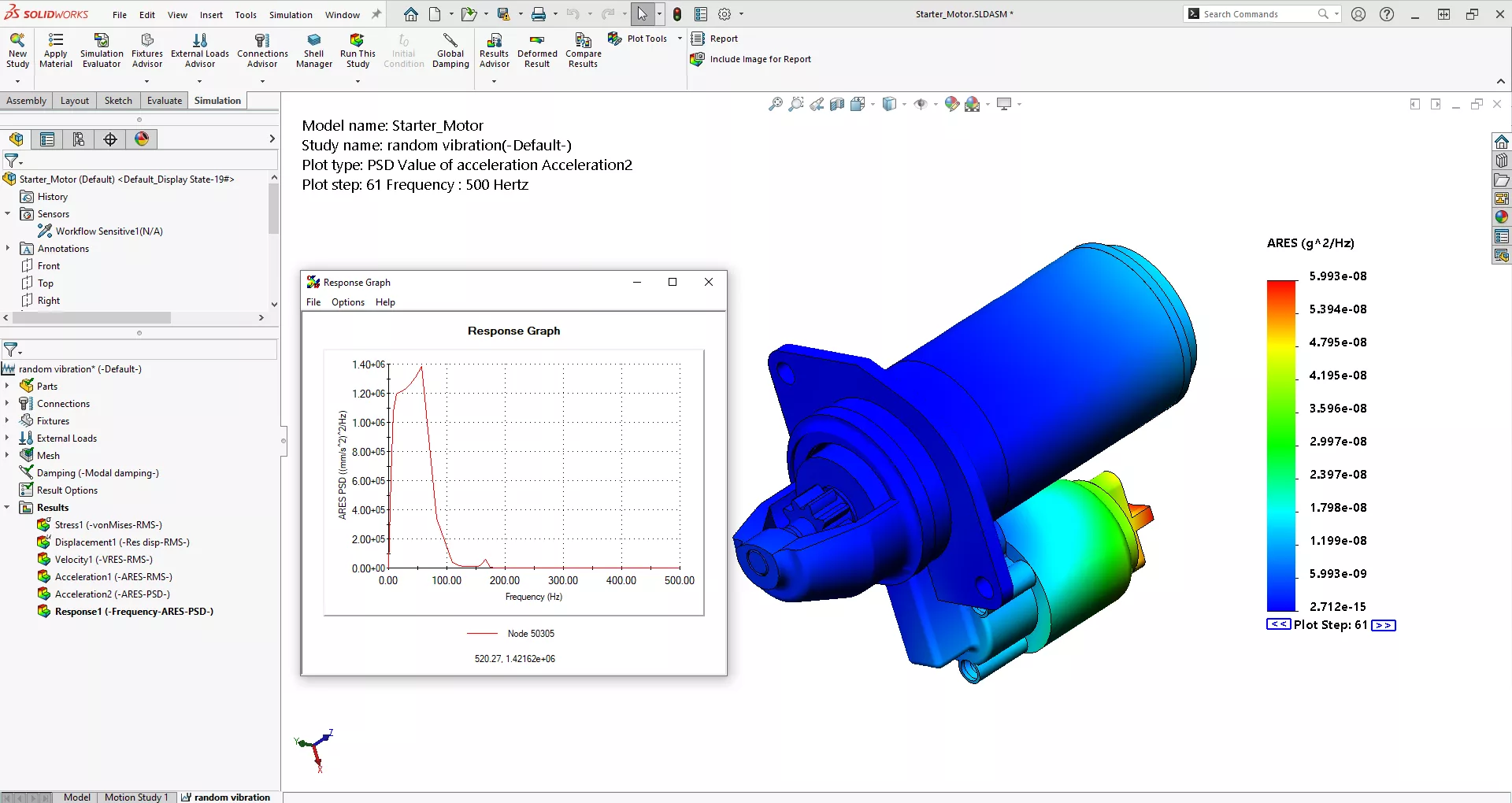
Analyze your structure’s steady-state response when exposed to a vibration environment using Harmonic and Random Vibration in SOLIDWORKS Simulation Premium. Vibration profiles can be input as a Power Spectral Density (PSD) curve or as a harmonic “frequency sweep” (shaker table test) and typical responses of stress and acceleration RMS values can be interpreted across the range of the frequencies tested.
Forced Vibration Analysis
Use the power and speed of Modal Superposition to find the transient behavior of your structural system. Great for low frequency shock events or in cases where the load is too fast to be considered Static. Users can examine vibration-induced accelerations and stresses to improve the robustness of their designs.
1 = Capability also available in SOLIDWORKS Premium
2 = Thermal analysis using CFD methodology is available in SOLIDWORKS Flow Simulation.

Simulation and You: Getting to the Truth of Analysis
While simulation has expanded beyond being an exclusive tool for analysts, many companies continue question whether analysis is an effective tool for their business. This paper will address these questions, including:
- How accurate do analyses need to be?
- Should they always be as precise as possible?
- What effect does simulation have on prototyping? Does it eliminate it? Lower it?
- Do analysis results take the place of experience in decision-making?
- Where else in development can simulation be used? Is it only verification and validation?
The role of analysis in development has changed and expanded. There are whole new parts of the development process where it can provide value. Download the whitepaper to learn more.
Frequently Asked Questions
As with all SOLIDWORKS tools, GoEngineer offers in-person and online training for all packages of SOLIDWORKS Simulation.
Example: If you are running SOLIDWORKS 2019, then SOLIDWORKS Simulation will also have to be 2019.
SOLIDWORKS Services:
Utilize GoEngineer’s Award Winning Support & Training for SOLIDWORKS
Award Winning Technical Support
GoEngineer's extensive SOLIDWORKS technical knowledge and world class support can help you succeed with SOLIDWORKS. Our award-winning team is ready to help you with any task you may have. Using state-of-art remote assistant technology software allows our team to solve most issues within one session. Reach out and see why GoEngineer is the #1 reseller of SOLIDWORKS and Stratasys systems in the world!
- 125+Certified Technical Specialists
- Email, Phone and Chat Support Available
- 98% Exceptional Customer Service Rating
PROFESSIONAL SOLIDWORKS TRAINING
GoEngineer offers online and classroom professional SOLIDWORKS training for organizations and individuals. All our instructors are SOLIDWORKS certified and teach thousands of students each year world wide. The curriculum is very diverse with numerous certified SOLIDWORKS courses to choose from. Each student will receive a Course Completion Certificate and preparation materials for SOLIDWORKS certification.
- Increase Your Earning Potential
- Led by Certified SOLIDWORKS Instructors
- Smaller Classes with Focused Attention
Additional Resources
Take Advantage of GoEngineer’s Extensive Knowledge Base and Resources

Find a Solution
Our robust Knowledge Base contains over 12,000 resources to help answer your product design questions. From basic CAD questions to in-depth guides and tutorials, find your solution here. Find a Solution

PROFESSIONAL TRAINING
Improve your skills with professional training and certifications in SOLIDWORKS, CAM, 3D Printing, and 3D Scanning offered four ways: self-paced, online, on-site, or in-classroom. Certified Training Courses

BLOG
#1 Technical Resource Worldwide - Right at your fingertips. Search or browse through hundreds of SOLIDWORKS tips & tricks, additive manufacturing product developments, announcements, how-to guides, and tutorials. Blog

YouTube Channel
Our YouTube channel hosts hundreds of educational tutorials, product demonstrations, recorded webinars, and best practices for all of our products and services. GoEngineer's YouTube Channel
ONLINE STORE
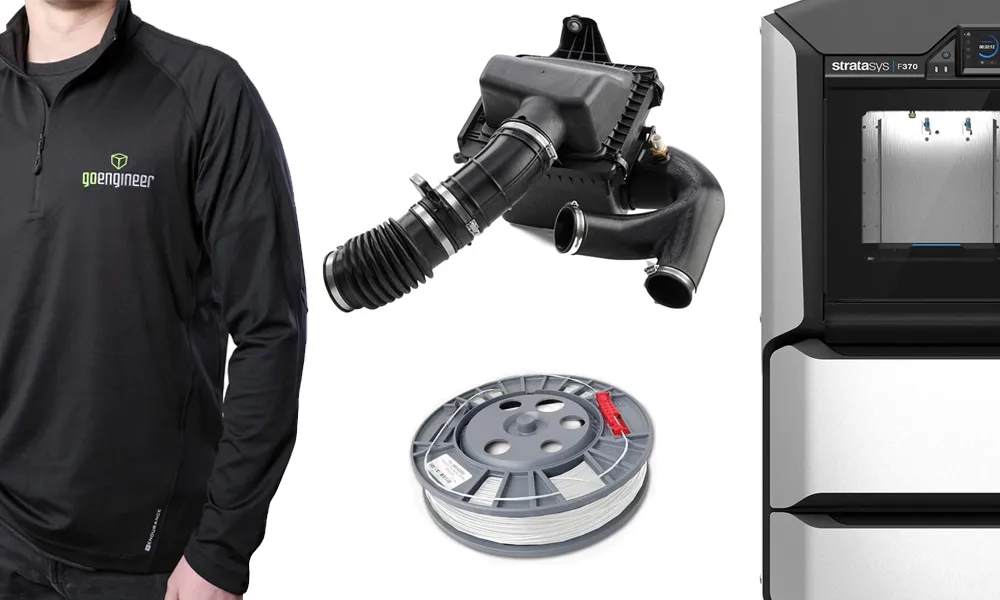
Order 3D printing materials and consumables, enroll in SOLIDWORKS training classes, and buy official GoEngineer gear directly from our online store. Online Store
WEBINARS
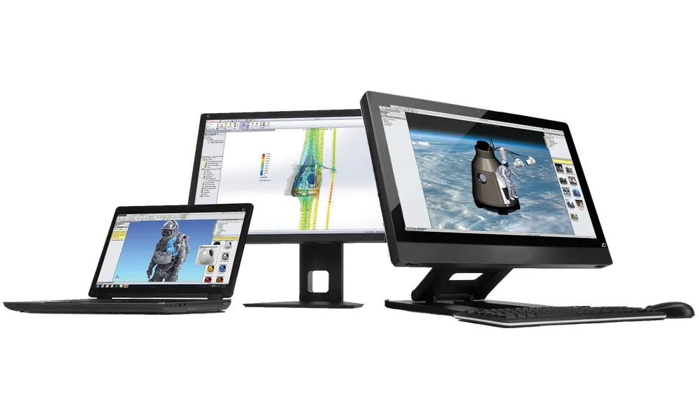
Our engineering webinars are hosted by some of the top experts in the industry. They are always recorded, always free, and always offer a live Q&A. WEBINARS
3D Printing Services
Need to 3D print a part? Our Additive Manufacturing experts will 3D print your part and deliver it to you using the latest technology on one of our professional FDM, PolyJet and SL 3D printers. 3D Printing Services