Geomagic Control X
A comprehensive metrology software platform
What is Geomagic Control X Software?
Geomagic Control X is a comprehensive metrology software platform that delivers the industry’s most powerful set of tools within straightforward workflows. The software enables Quality Control Managers intuitive, fast, repeatable controls for the inspection measuring process. Information-rich analysis and reporting functions allow for significant productivity gains in any manufacturing workflow.
Tools
GEOMAGIC CONTROL X
Powerful tools within a straightforward workflow.
Scan data processing
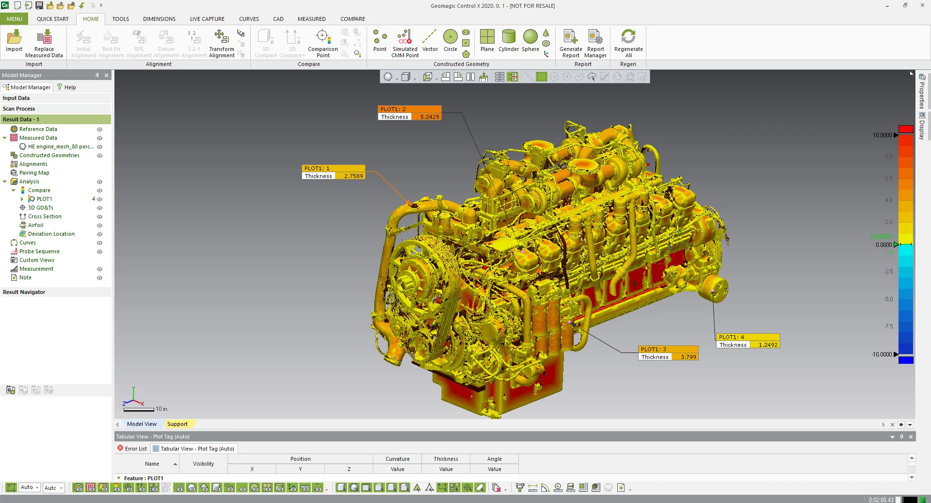
One of the most powerful advantages of use of Control X is that it can handle large numbers of Measured Data which could not be handled by other software. It was developed from the ground up to work with scan data sets with point clouds or triangulated data in the tens or hundreds of millions.
PMI/MBD support
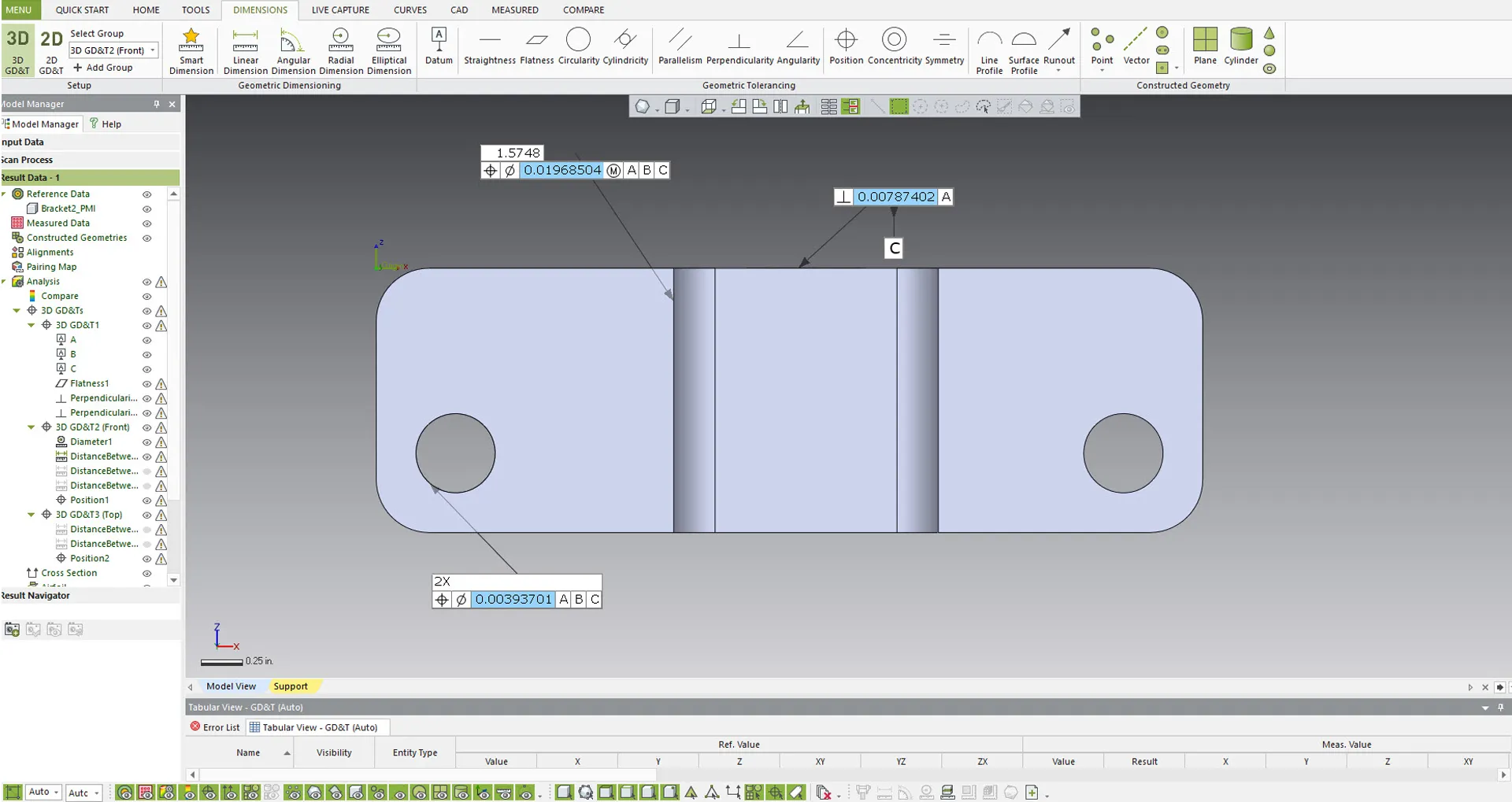
Companies that implement Product Manufacturing Information (PMI) or Model Based Definition in their 3D CAD models can take full advantage of having the GD&T information included in the CAD import. This feature essentially automatically generates an inspection plan in Control X, saving hours of time. CX supports Solidworks, Catia V5/6, Creo and NX part files.
Batch processing
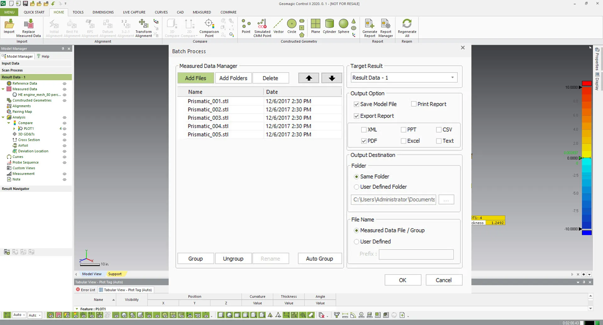
The powerful Batch Process tools execute a series of programs or “jobs” on a computer without manual intervention by taking a multiple set of Measured Data files as input, processing the data, and outputting a set of data files. This can be useful Processing jobs when computer resources are less busy, and Avoid idling computing resources with minute-by-minute intervention and supervision
GD&T TOOLs
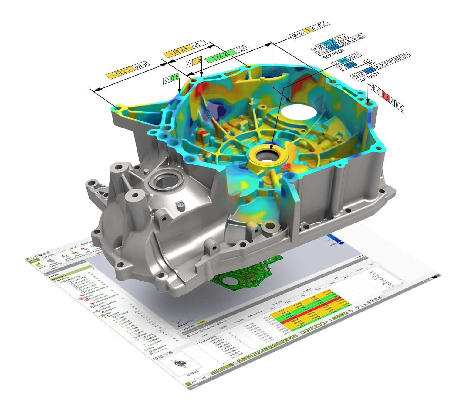
The GD&T (Geometric Dimensioning and Tolerancing) Tools menu provides tools necessary for analyzing the size, form, orientation, and location of features in 3D space as well as evaluating the Pass/Fail status of features within a user-defined tolerance. The size of features can be analyzed using geometric dimensions such as Linear Dimension, Angular Dimension, Radial Dimension, etc. The form, orientation, and location of features can be analyzed using geometric tolerances such as Flatness, Circularity, Cylindricity, Parallelism, etc.
Robust Alignment tools
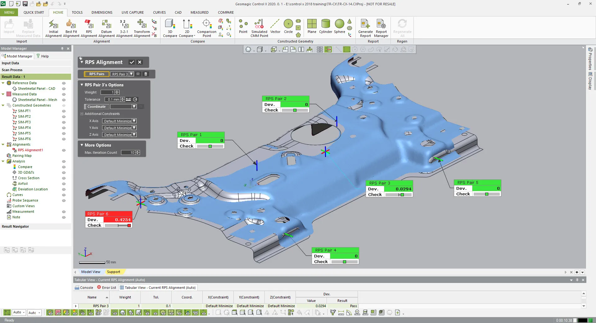
Control X contains many automated alignment and dynamically-guided workflow alignment options. Users can use either scan data or probing devices to align the measured part to the CAD or nominal mesh model. Some of the alignment options are best-fit, 3-2-1, datum, Reference Point System (RPS), and Live Align using a probing device.
Integration
Wide integration with many hardware measuring devices. Control X can import over 100 file types used as measured or CAD data and has quite a list of direct compatibility with major 3D scanners and Portable CMM’s (Probe/Scan Articulating Arms and Optical CMM’s). Users can connect to these devices and measure directly into the software without having to import the data from another software.
Frequently Asked Questions
Control X Features
Robust Analysis tools
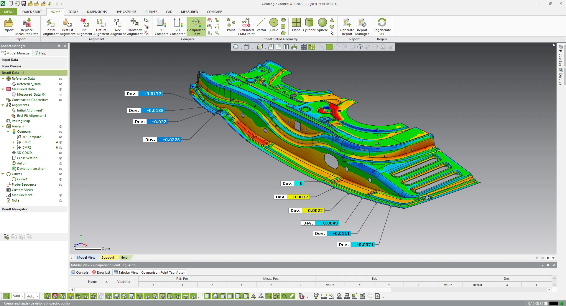
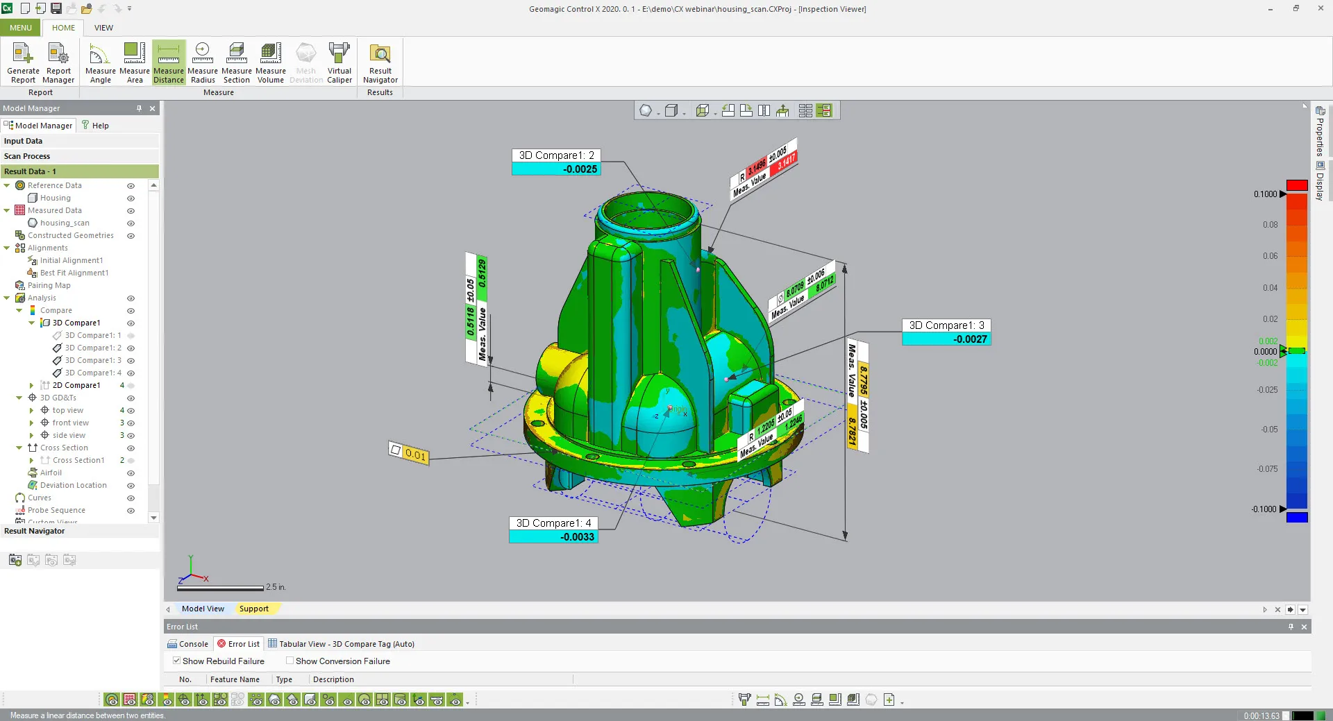
Within Control X there are a comprehensive set of both 3D and 2D analysis tools which can be displayed over the entire part or localized to show more detail. Common analysis such as 3D or 2D Compare can be generated with few clicks, and annotations added with a variety of display options. Other unique tools are showing a thickness plot, virtual edge and boundary deviation for sheetmetal applications. The Simulated CMM Point command makes constructed points by simulating a CMM (Coordinate Measuring Machine) or probing device. You can measure a point on the measured data like a real probing device and get difference between the Reference Data and the Measured Data.
Result Navigator
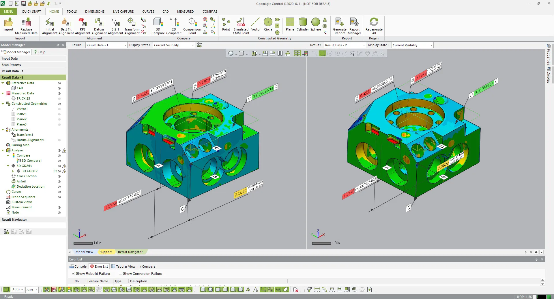
All reference and measured data along with dimensions, analyses, cross sections etc. are stored in the Result Data tab. The Result Data tab can consist of a combination of multiple results in a single inspection project as required. The inspection project can have multiple Result Data tabs. With having multiple Result Data tabs, you can compare results you measured in different conditions at a time. With the Result Tools, you can add a new Result Data tab, delete an existing Result Data tab, or duplicate Result Data tabs. Additionally, in the Result Navigator, you can review the results inspected in different Result Data tabs.
Control X Inspection Viewer
Inspection Viewer is a free viewer application for Geomagic supported file formats. With Viewer, you can share data throughout your organization, with the ability to view Geomagic’s native formats (xrl, xdl and mdl), including all of the following data entities: Point clouds, polygon meshes, curves, surfaces, solids, notes, reference geometries, GD&Ts, Scan-to-CAD comparison plots, Scan-to-CAD sectional deviation plots, annotations, geometric tolerances, dimensions and inspection reports. Workgroups use Inspection Viewer to share information, view 3D models, read inspection results with detailed deviation information, add notes, and freely share information with your partners. Individual users now have a no-cost product to view and measure dense 3D point cloud data, something that few other applications can offer.
Additional Resources
Take Advantage of GoEngineer’s Extensive Knowledge Base and Resources

Find a Solution
Our robust Knowledge Base contains over 12,000 resources to help answer your product design questions. From basic CAD questions to in-depth guides and tutorials, find your solution here. Find a Solution

PROFESSIONAL TRAINING
Improve your skills with professional training and certifications in SOLIDWORKS, CAM, 3D Printing, and 3D Scanning offered four ways: self-paced, online, on-site, or in-classroom. Certified Training Courses

BLOG
#1 Technical Resource Worldwide - Right at your fingertips. Search or browse through hundreds of SOLIDWORKS tips & tricks, additive manufacturing product developments, announcements, how-to guides, and tutorials. Blog

YouTube Channel
Our YouTube channel hosts hundreds of educational tutorials, product demonstrations, recorded webinars, and best practices for all of our products and services. GoEngineer's YouTube Channel
ONLINE STORE
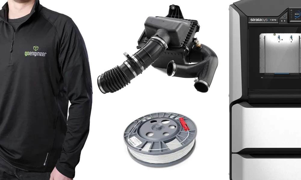
Order 3D printing materials and consumables, enroll in SOLIDWORKS training classes, and buy official GoEngineer gear directly from our online store. Online Store
WEBINARS
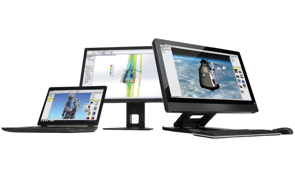
Our engineering webinars are hosted by some of the top experts in the industry. They are always recorded, always free, and always offer a live Q&A. WEBINARS
3D Printing Services
Need to 3D print a part? Our Additive Manufacturing experts will 3D print your part and deliver it to you using the latest technology on one of our professional FDM, PolyJet and SL 3D printers. 3D Printing Services