SOLIDWORKS Limit Angle Mate Tutorial
The Advanced Mate options are handy for arranging your SOLIDWORKS assembly as they would appear in the real world. In this quick tip, we explore options to set up a limit angle mate between two parts when there aren’t two parallel faces to select.
In Figure 1, we have an assembly of a set of Allen keys. The assembly is made of varying sizes of Allen keys that are stored within a formed sheet metal holder.
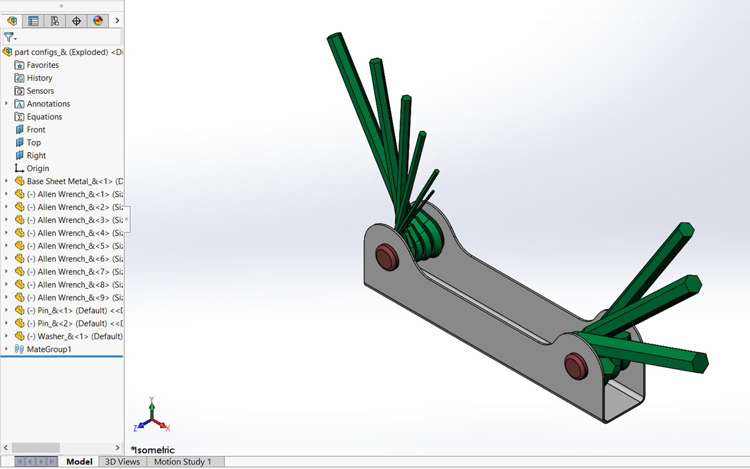
Figure 1: Allen key assembly
If we examine one of the keys (Figure 2), we see three existing mates used to position the key in the assembly:
- A Coincident mate between an axis of the Allen key and the center pin allows the part to pivot into its stored position and a range of extended positions.
- Two Coincident mates to keep the part positioned in place along the Z axis.
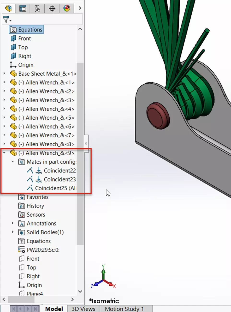
Figure 2: Mates used to position the Allen key in the assembly
Discovering and Preventing Interferences
As shown in Figure 3, there is still one degree of freedom for the Allen key. In its current state, the key can move in a way that would interfere with the holder, which would be impossible in the real world. To keep this interference from occurring, we will add a Limit Angle Mate.
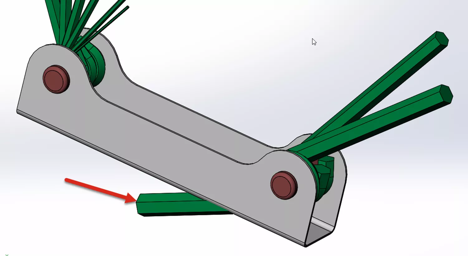
Figure 3: The Allen key can interfere with the handle in the assembly
The Limit Angle mate allows a part to move anywhere between a set minimum and maximum value. In most cases, one parallel face of each part is selected. With this assembly, there isn’t a face on the Allen key that is parallel with the inside face of the holder.
Adding the Limit Angle Mate
To add the Limit Angle Mate, launch the Mate tool in the CommandManager Toolbar (Figure 4).
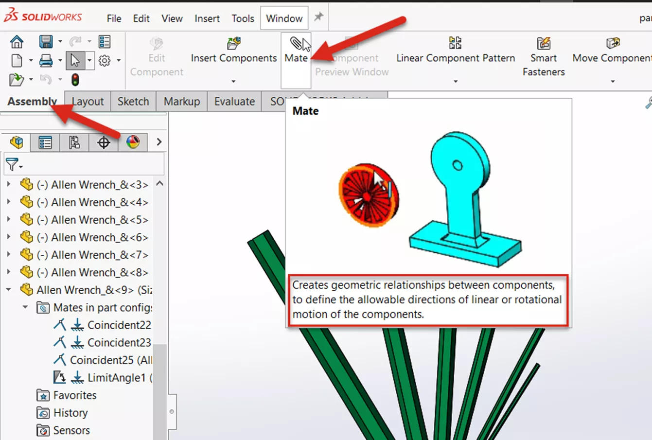
Figure 4: Locating the Mate command in the CommandManager toolbar
The Limit Angle Mate is found in the Advanced tab in the Mate Properties (Figure 5). The inside face of the holder and the Top Plane used to create the Allen key are selected. (Individual results may vary depending on the orientation of your own models.)
The Starting angle can be used to position the part before setting the Minimum and Maximum angles. For this example, a minimum angle of 10 degrees and a maximum angle of 130 degrees are selected.
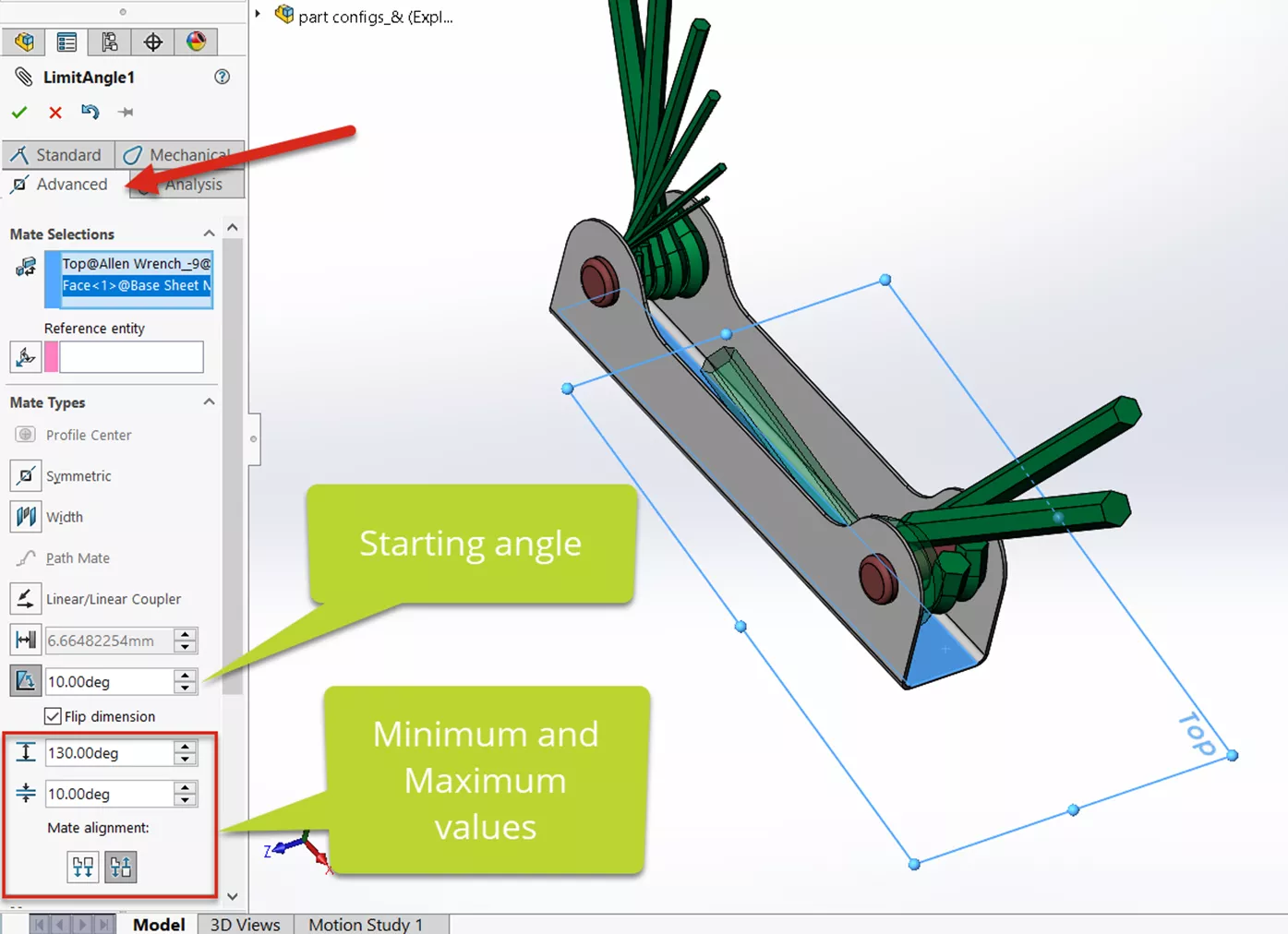
Figure 5: Setting the minimum and maximum angles for the Limit Angle Mate
Testing the Limit Angle Mate
Testing the new mate is as easy as clicking the left mouse button on the Allen key and dragging it. The Limit Angle Mate will allow you to move the part to the Minimum and Maximum values (10 degrees and 130 degrees). (Figure 6)
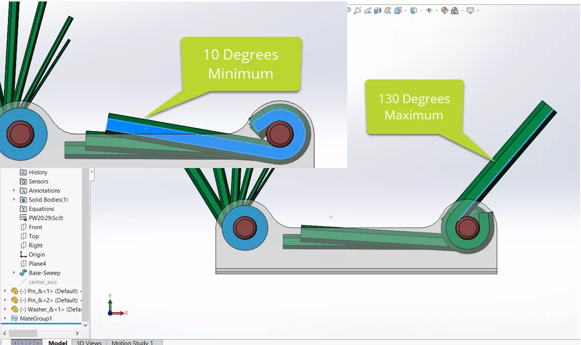
Figure 6: Testing the Minimum and Maximum angles
I hope you found this quick tip explaining Limit Angle Mates in SOLIDWORKS helpful. Check out more tips and tricks below. Additionally, join the GoEngineer Community to participate in the conversation, create forum posts, and answer questions from other SOLIDWORKS users.
Want to take your SOLIDWORKS skills to the next level? Enroll in the official SOLIDWORKS Assembly Modeling Training Course. Both self-paced and in-person training options are available.

SOLIDWORKS CAD Cheat Sheet
SHORTCUTS ⋅ MOUSE GESTURES ⋅ HOT KEYS
Our SOLIDWORKS CAD Cheat Sheet, featuring over 90 tips and tricks, will help speed up your process.
More SOLIDWORKS Tutorials
Introduction to SOLIDWORKS Mates: Standard, Advanced, & Mechanical
SOLIDWORKS Magnetic Mates Explained
Using SOLIDWORKS Copy with Mates
SOLIDWORKS Mate Controller Explained
![]()
About GoEngineer
GoEngineer delivers software, technology, and expertise that enable companies to unlock design innovation and deliver better products faster. With more than 40 years of experience and tens of thousands of customers in high tech, medical, machine design, energy and other industries, GoEngineer provides best-in-class design solutions from SOLIDWORKS CAD, Stratasys 3D printing, Creaform & Artec 3D scanning, CAMWorks, PLM, and more
Get our wide array of technical resources delivered right to your inbox.
Unsubscribe at any time.