How to Create Simple 3D Models with DraftSight
In a previous article, Using Sketched Contours to Create 3D Extrusion in DraftSight, I demonstrated a method for creating a closed contour with a polyline or with sketch entities and the Weld command. Then, using the Extrude command to create a solid body. This method may be used with any version of DraftSight. In DraftSight 101 - Basic 3D Shapes, I demonstrated the methods for creating basic 3D shapes using DraftSight Premium or DraftSight Enterprise Plus.
For this demonstration, I will use the basic 3D shapes from the 3D Modeling Workspace to create overlapping solids, which I will combine or subtract to achieve the desired shape.
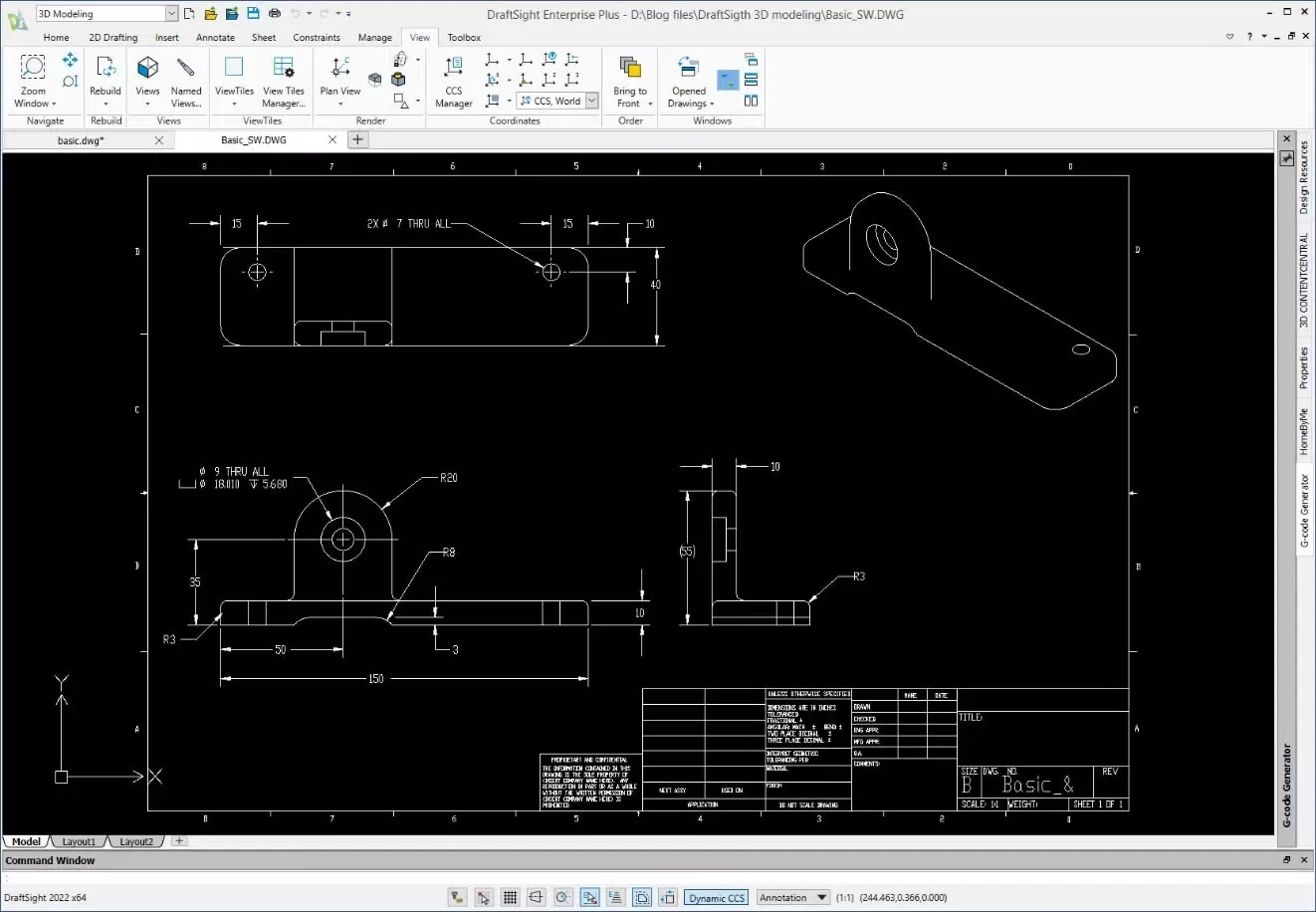
Here is a drawing of the part I will be creating:
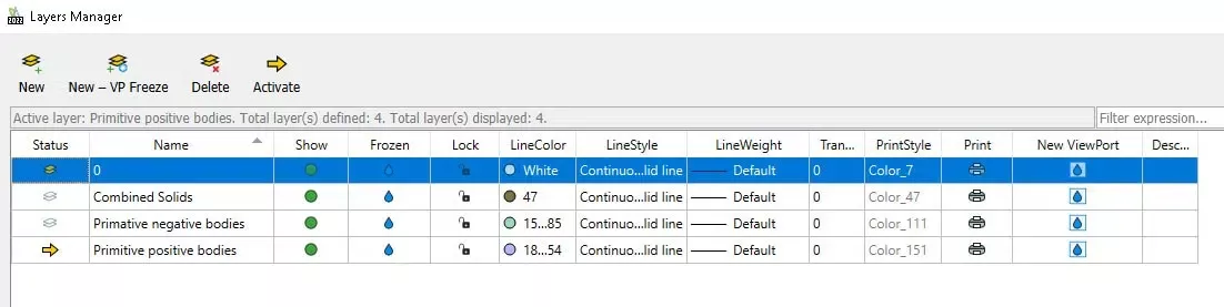
I will start by setting up the layers to organize my 3D shapes.
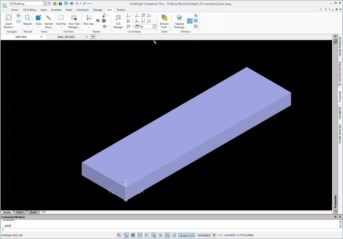
Next, I will create a Box, 40mm x 150mm x 10mm with the bottom left corner on the Origin. This will be the Base for the part.
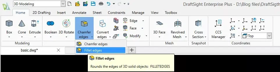
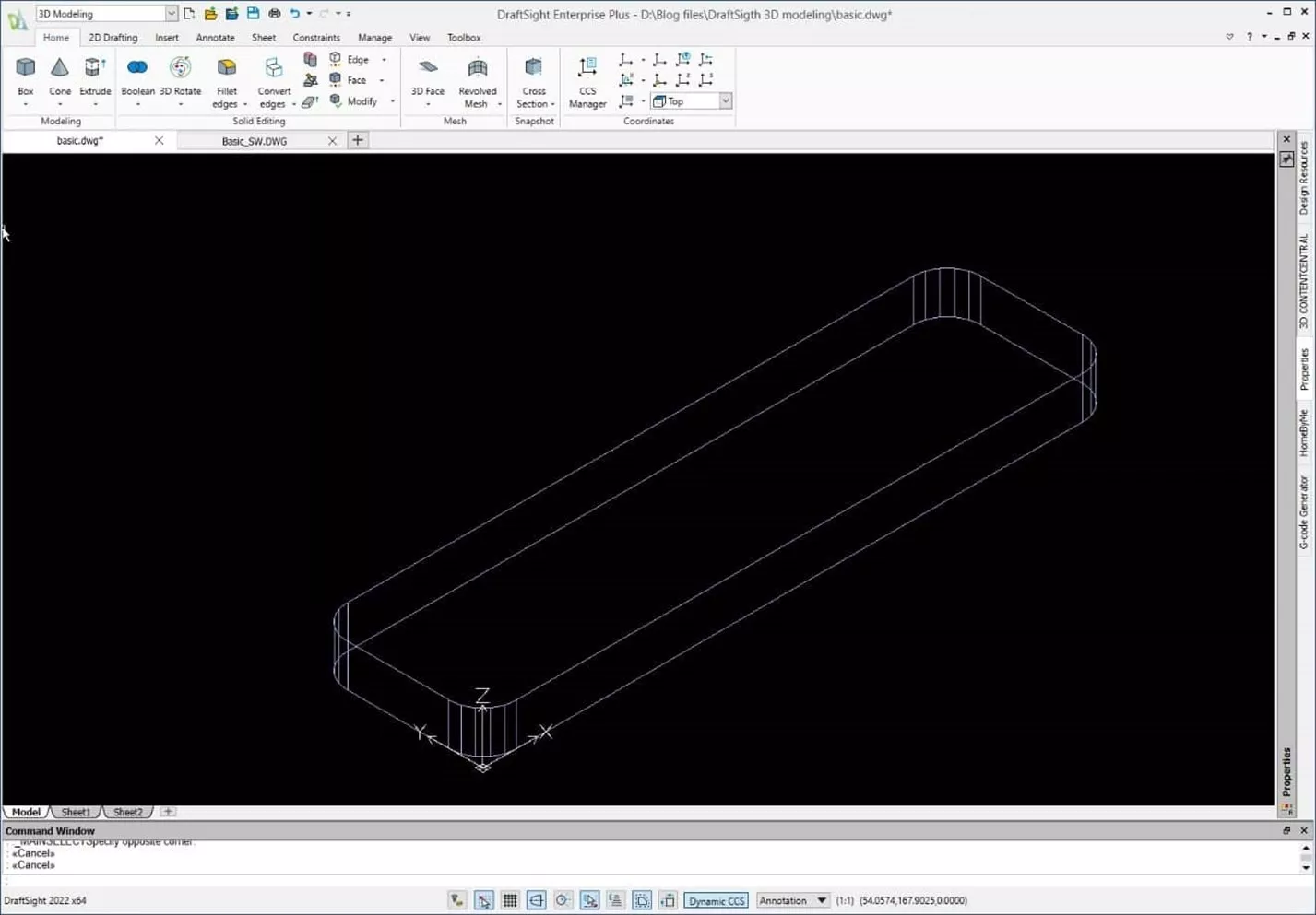
I will use the Fillet tool to create 8mm fillets on the corners.
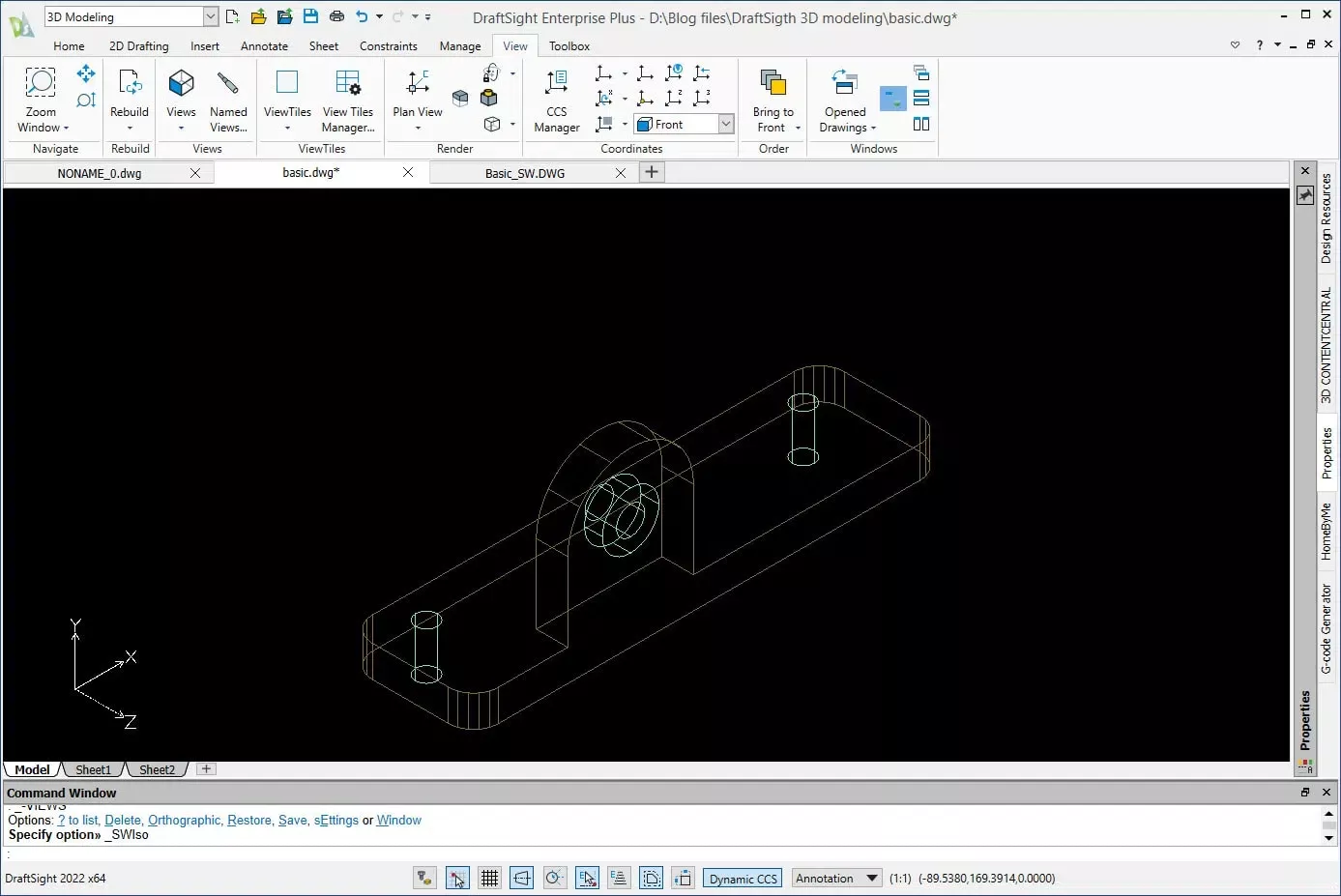
Changing the render to wireframe makes it easier to collect the edges.
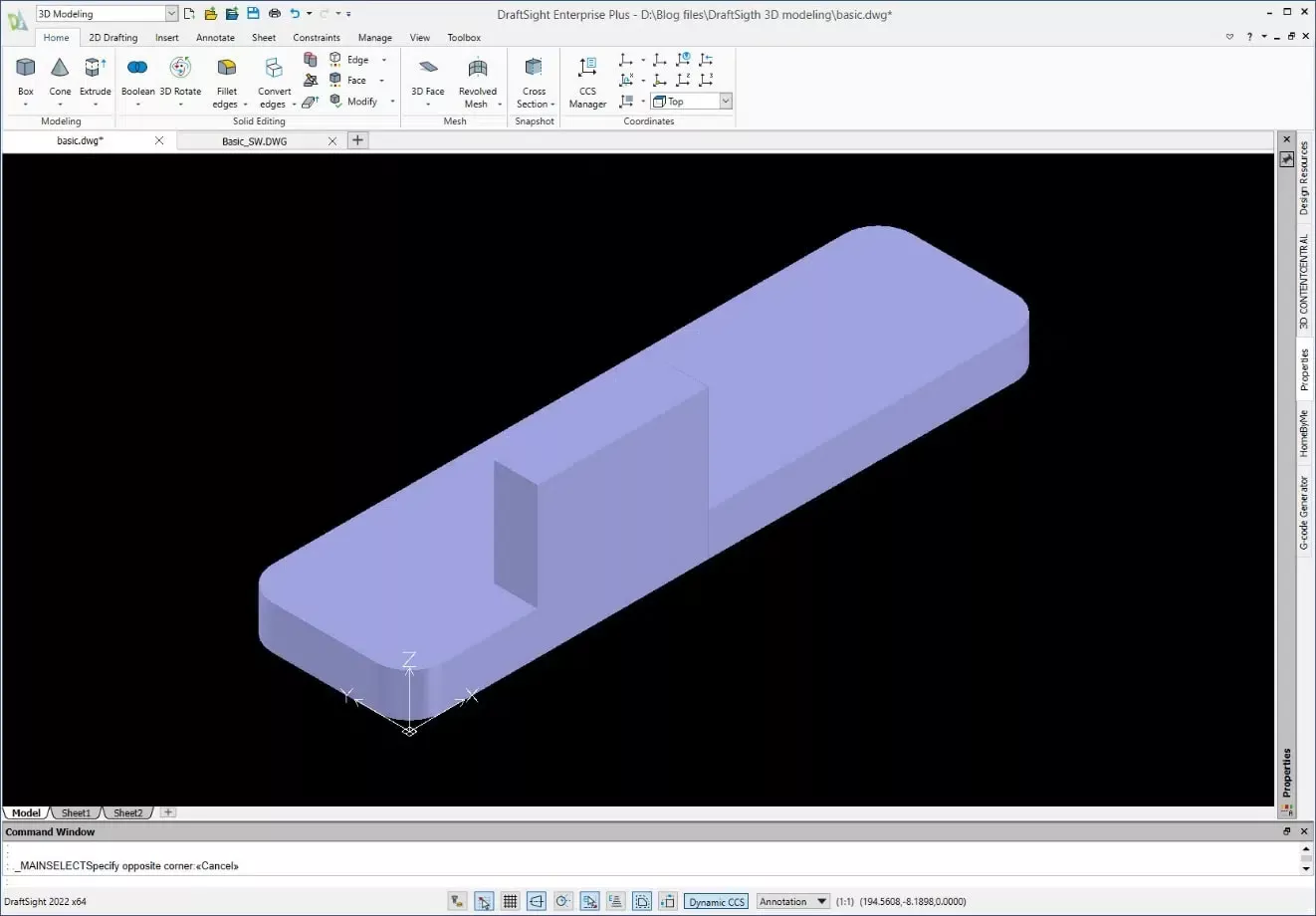
Next, I will create another box 40mm x 10mm x 30mm located on the front face of the base body at 0, 30, 0. This will be the rectangular portion of the vertical tombstone shape.
Now, I will create the last of the positive primitive shapes by adding a cylinder at the midpoint of the edge of the vertical rectangle.
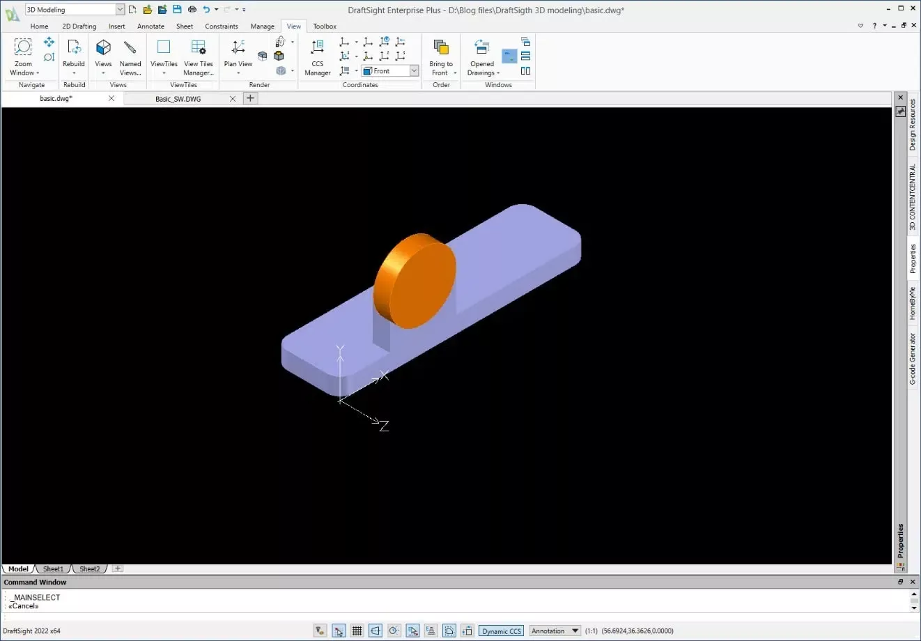
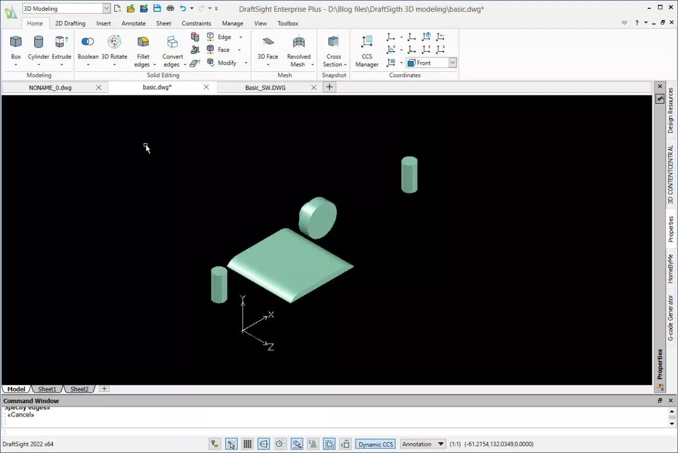
Here are the separate rendered solids (there are three).
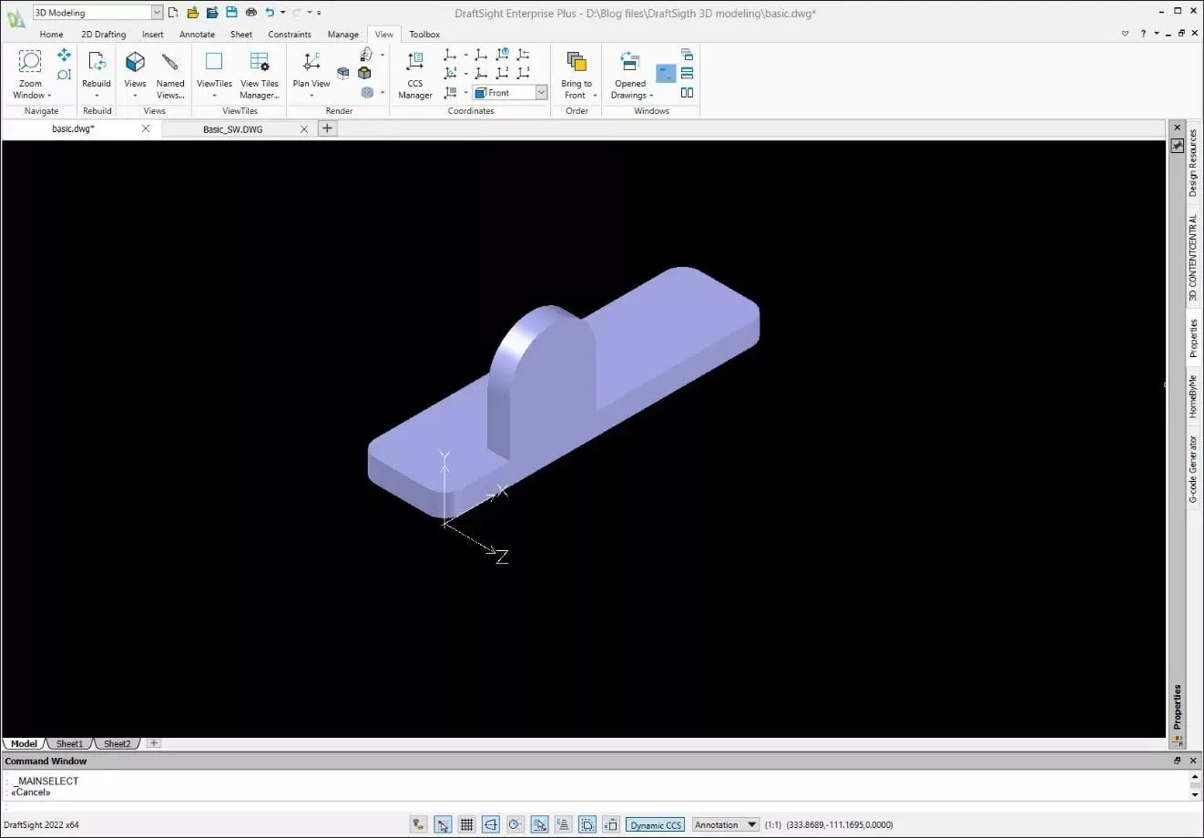
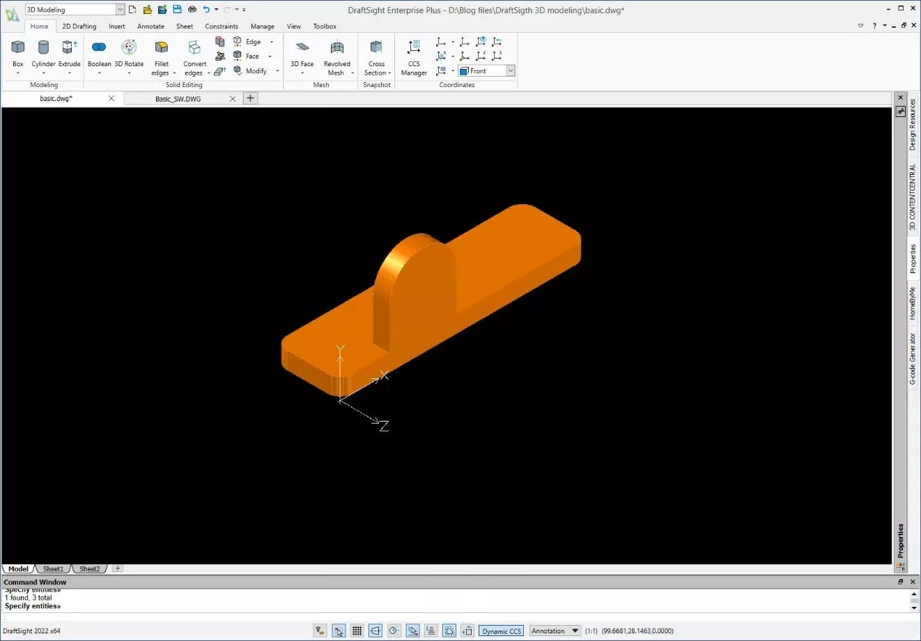
Now it’s time to combine the three solids into a single 3D shape using the Union command.
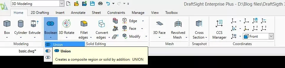
After selecting the three solids and completing the command, if I hover over the solid it looks like this:
I will move it to the Combined solids layer by activating the layer and moving the body to it.
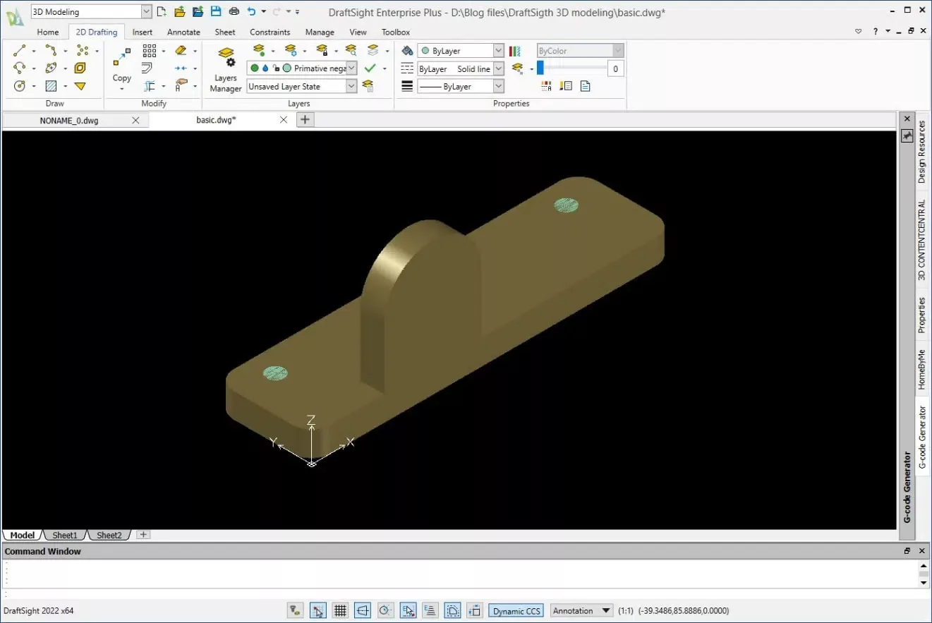
Now, I will begin to create the primitive solids used for the cuts. To start I will activate the layer for the primitive negative bodies and create two cylinders offset from the corners by 15mm from the outside edge and 10mm from the top edge of the base.
I need to create two cylinders at the center of the vertical boss, one 18mm Dia x 5.68mm deep and one 9mm Dia x 10mm deep.
I will create a Box 40mm x 3mm x 40mm for the undercut and add 8mm fillets.
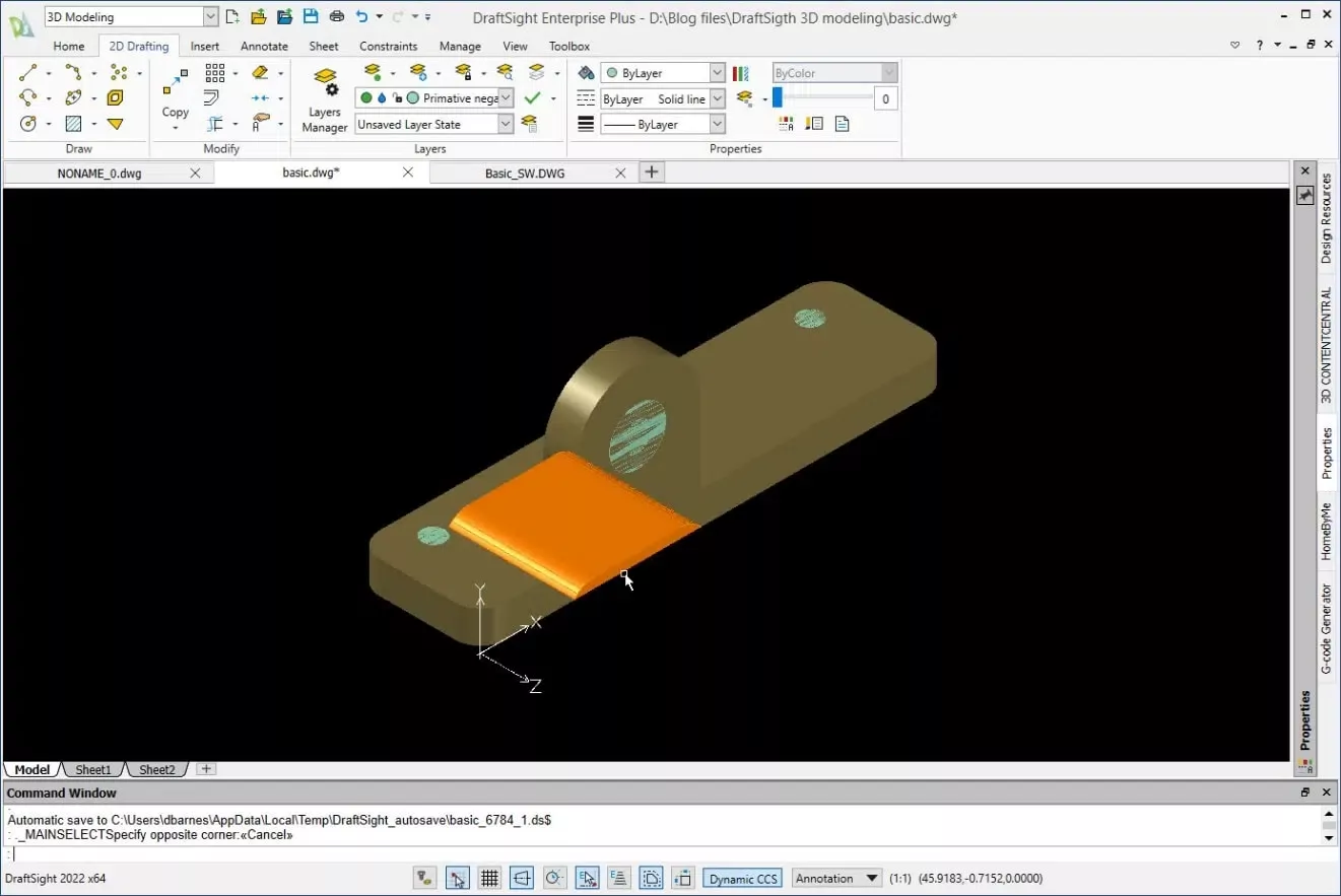
This is what all of the bodies that will be subtracted from the primary body look like.
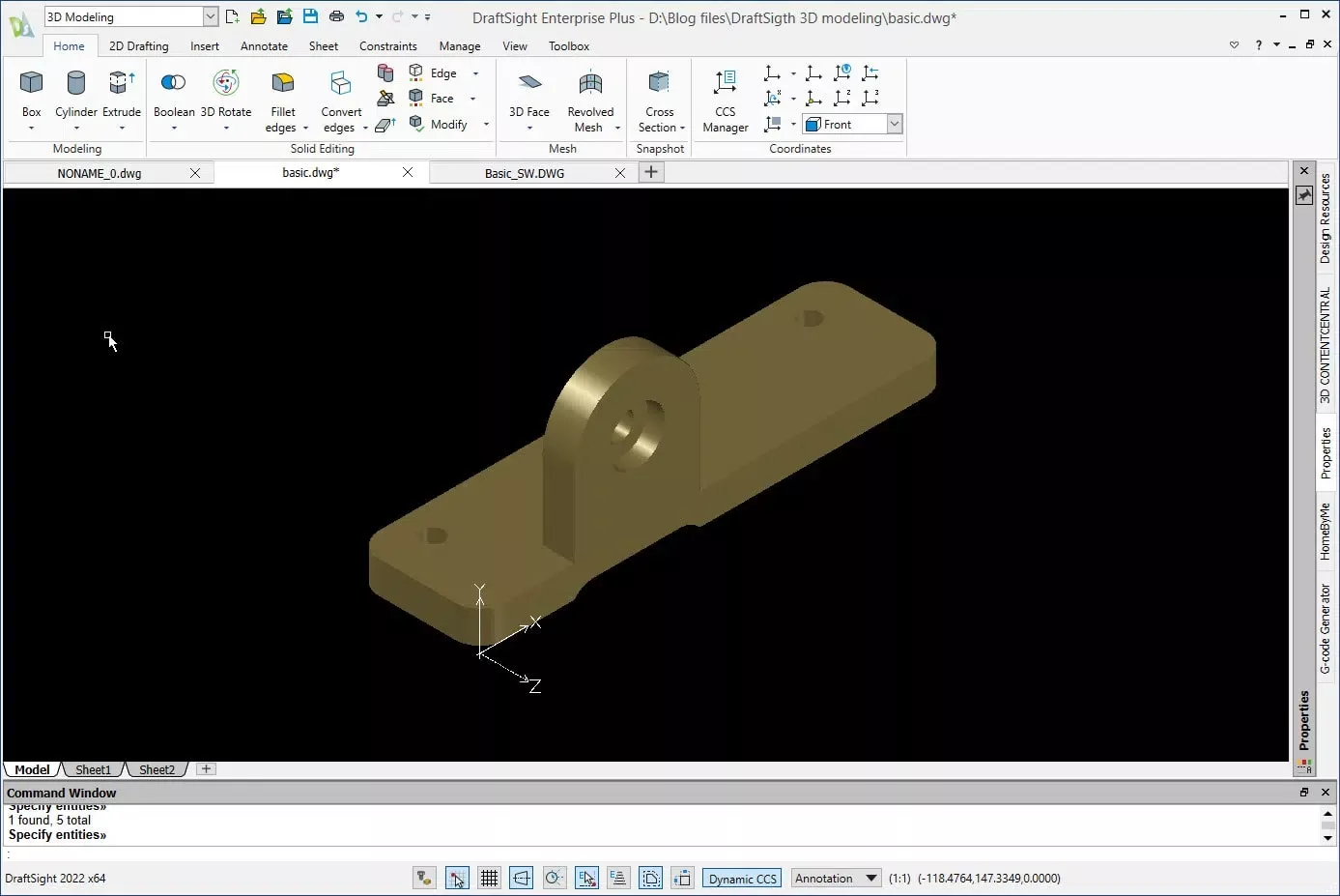
For the last step, I will use the Subtract command to remove the primitive solids used for the cuts from the primary solid. This will leave me with the completed body.
I hope you found this tutorial for creating simple 3D models with DraftSight helpful. Check out more tips and tricks below. Additionally, join the GoEngineer Community to create forum posts, enter design contests, and answer questions from other DraftSight users.
DraftSight Training
Want to take your DraftSight skills to the next level? Enroll in our DraftSight Essentials online training course. For new users and former AutoCAD users, this course is designed to use the DraftSight software through the user interface. Learn how to make coordinates, create drawings, modify entities, properties, and more.

Related Articles
DraftSight Make Flat Snapshot Workaround
Master Layers in DraftSight with Layer States Manager
How to Use AutoStack in DraftSight
Transfer DraftSight Workspace to New Installation

About Dennis Barnes
Dennis Barnes is a CSWE, CSWI and a Sr. Applications Engineer based out of the Albuquerque, NM office since 2012. He has a BS in Computer Science from Chapman University and has been using SOLIDWORKS since 2005.
Get our wide array of technical resources delivered right to your inbox.
Unsubscribe at any time.