Using Sketched Contours to Create 3D Extrusions in DraftSight
This blog demonstrates how to use sketched contours to create 3D extrusions in DraftSight.
Use the Extrude command to create a solid from a contour.
From DraftSight Help: “The Extrude command creates solid primitives by extruding closed 2D entities such as PolyLines, Circles, Ellipses, and Regions. Use the Extrude command to create 3D solids or 3D surfaces.”
Let's start with a simple shape from a SOLIDWORKS Essentials training exercise.
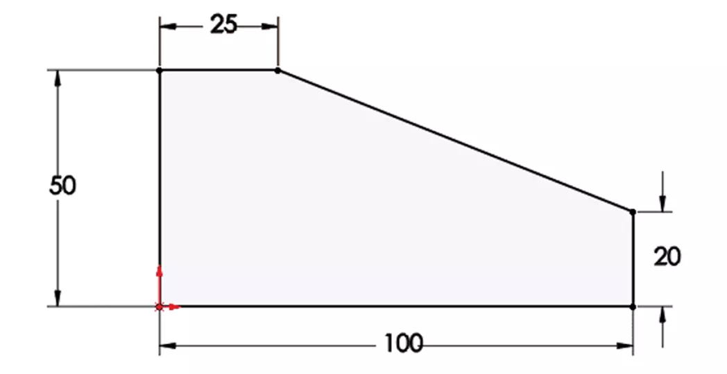
Then, create the shape in DraftSight using the Polyline tool, which will create a closed contour of continuous lines.
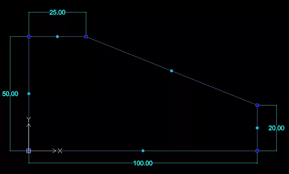
Here is what the Polyline contour looks like when a single line is selected.
If you draw the shape using the Line tool, it will look like this when all of the lines are selected.
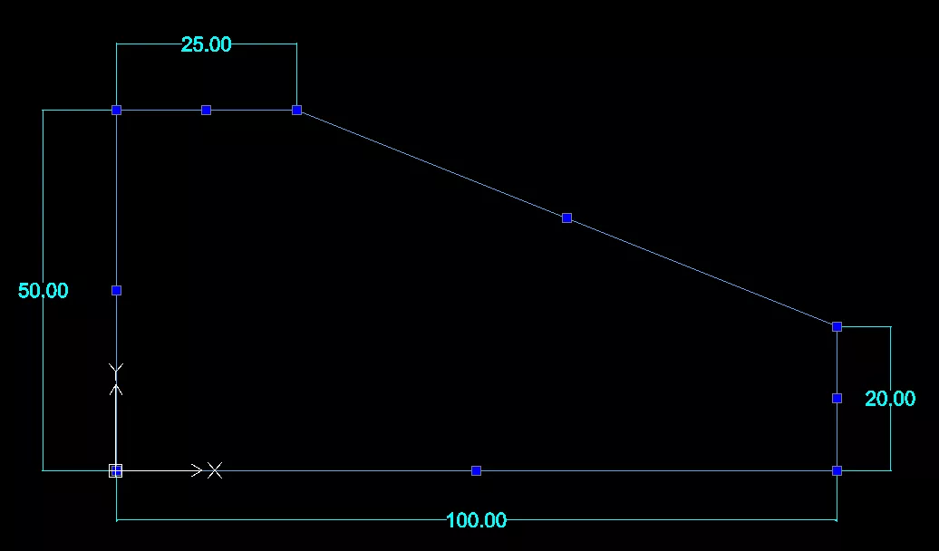
The Polyline sketch is a single region, while the Line sketch is five separate entities. To use it for the Extrude command, you must convert the lines into a Polyline or a 2D Region entity.
From DraftSight Help: Creating Regions
"The Region command transforms an entity that forms a closed shape into a 2D Region entity. You can use the command to combine all entities of any closed loop – such as closed PolyLines (including polygons and Rings), Circles, Ellipses, and closed Splines – into one entity.
After creating a Region, there is little visual difference on screen except when the original entity had a width, thickness, or LineWeight. This information is lost when you create a region from such entities.
A Region is a planar solid entity. If you set ShadeView mode to Flat, you will see that the Region is a surface, not simply a boundary contour.
If the source entities of the Region are hatched, the Hatch loses associativity to the boundary. You must apply the Hatch to the Region entity again.
You can also create Regions with the AreaBoundary command by setting the resulting entity type for boundaries to Region."
Another method would be to convert the lines to a continuous polyline using either the Weld or Join command.
From DraftSight Help: Welding Entities
"Use the Weld command to merge two entities into one. You can merge Lines, open PolyLines, Arcs, elliptical Arcs, or open Splines. You can also transform Arcs to Circles and elliptical Arcs to Ellipses.
Use these guidelines when welding entities:
- Lines must be aligned in one direction. You can join Lines that are co-linear, in which case the farthest end points remain and a new line connects them.
- Lines that are not co-linear, without space between them, are joined to a PolyLine.
- Arcs must share the same center point and radius. Arcs are joined counterclockwise beginning from the source entity.
- Elliptical Arcs must lie on the same Ellipse. Elliptical Arcs are joined counterclockwise beginning from the source entity.
- PolyLines can join Lines, Arcs, or PolyLines resulting in a single PolyLine. You can only merge entities that lie end-to-end to the source PolyLine and attached specified entities. The entities must lie on the same plane. Unlike joining Lines, Arcs, or elliptical Arcs, you cannot join entities with a space between them if the source entity is a PolyLine. Note that the EditPolyLine command also lets you join entities to existing PolyLines.
- Splines must have no gaps between them. The appearance of the Spline changes if the transition between the origin entities is not tangential.
Either command will prepare the sketch for the Extrude command.
Change the view to SW Isometric.
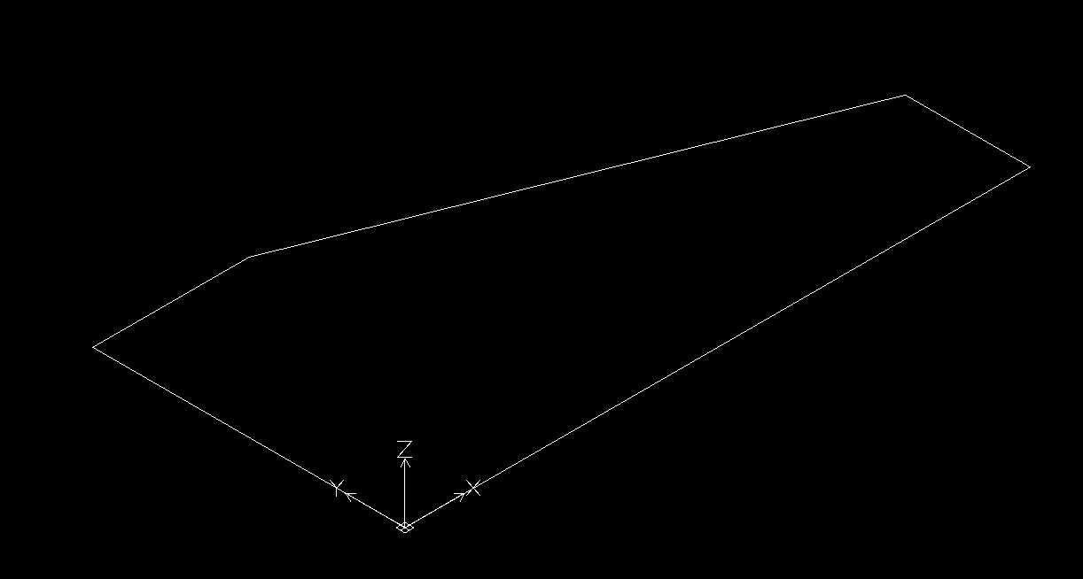
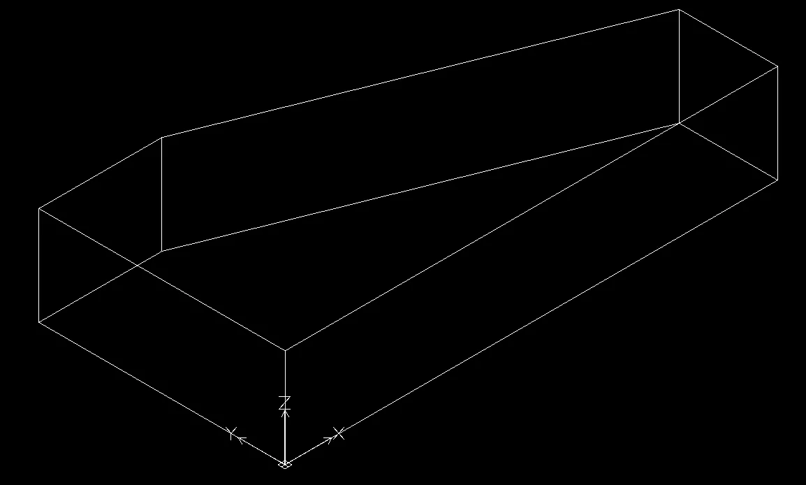
Type Extrude in the command line. Set the height to 20 and the result should look like this:
To change the appearance use the Hide or Hideview command. This will hide the lines behind the view. Like this:
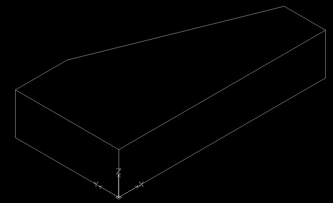
Or, you could use the shading commands:
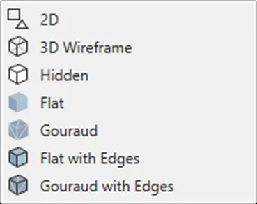
For example, using the Flat with Edges command will result in this:

I hope you enjoyed this demonstration of the Extrude command to create 3D solids from closed contours in DraftSight. Check out more tips and tricks below. Additionally, join the GoEngineer Community to create forum posts, enter design contests, and answer questions from other DraftSight users.
DraftSight Training
Want to take your DraftSight skills to the next level? Enroll in our DraftSight Essentials online training course. For new users and former AutoCAD users, this course is designed to use the DraftSight software through the user interface. Learn how to make coordinates, create drawings, modify entities, properties, and more.

Related Articles
How to Create Simple 3D Models with DraftSight
DraftSight Make Flat Snapshot Workaround
Master Layers in DraftSight with Layer States Manager
How to Use AutoStack in DraftSight

About Dennis Barnes
Dennis Barnes is a CSWE, CSWI and a Sr. Applications Engineer based out of the Albuquerque, NM office since 2012. He has a BS in Computer Science from Chapman University and has been using SOLIDWORKS since 2005.
Get our wide array of technical resources delivered right to your inbox.
Unsubscribe at any time.