SOLIDWORKS Mass Moments of Inertia Explained
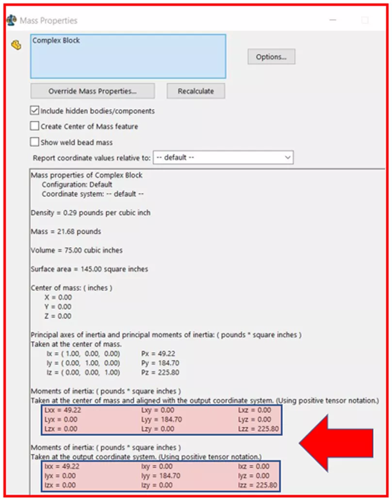
We have all referred to Mass Properties when working with solid models, especially when taking SOLIDWORKS certifications! For the most part, useful information is available at a glance: Density, Mass, Volume, Surface Area, etc. But how does someone interpret the rest of the information included in Mass Properties, particularly the numbers at the bottom? What exactly are they telling us?
It all goes back to Moments of Inertia which depend on an object’s mass, shape, and axis of rotation.
Every object has a Center of Mass that, if suspended in midair from this point, will be perfectly balanced. Taking the following symmetrical complex block as an example, we can see the principal axes through its center of mass.
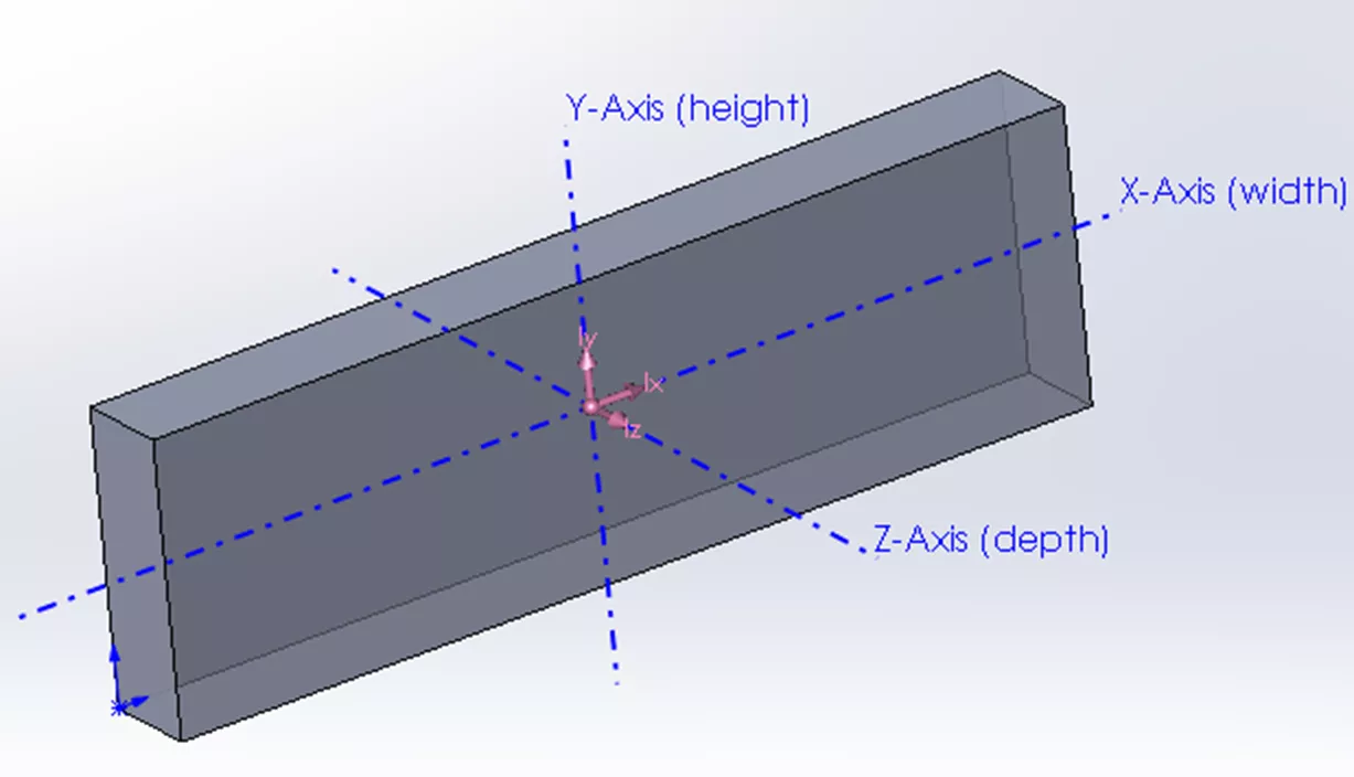
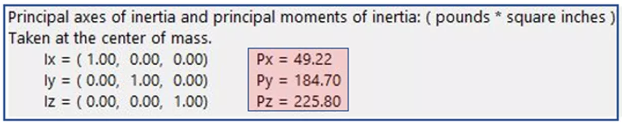
If the block rotated about any one of these axes, we would see principal Mass-Moment of Inertia values which are displayed in units of ML2. These values represent the distribution of mass about each axis.
The groups of numbers (3x3 matrices) at the bottom of the Mass-Properties window represent Inertia Tensors.
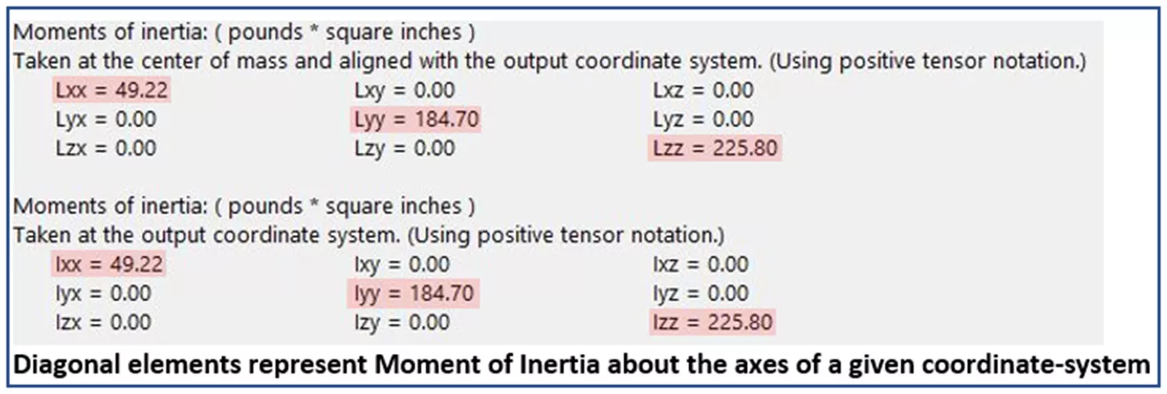
Without getting too technical, the diagonal elements of these matrices always represent Mass Moments of Inertia about the primary axes of an established coordinate system. Any non-diagonal element represents a Cross-Product MOI. Cross-product MOI is really just an indication of the symmetry of the object. If it is non-zero then we can expect an off-axis torque or acceleration that will result in a wobble of the object; not a pure rotation. Think of a car wheel being balanced to prevent wobbling.
Let’s look at an example of an object that is symmetrical about only one plane (XY):
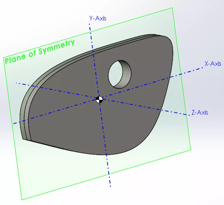
Here we see zero values for all cross-products containing the Z-axis (no wobble in the Z-direction). This is because the object’s mass is balanced equally along this axis on both sides of the plane of symmetry.
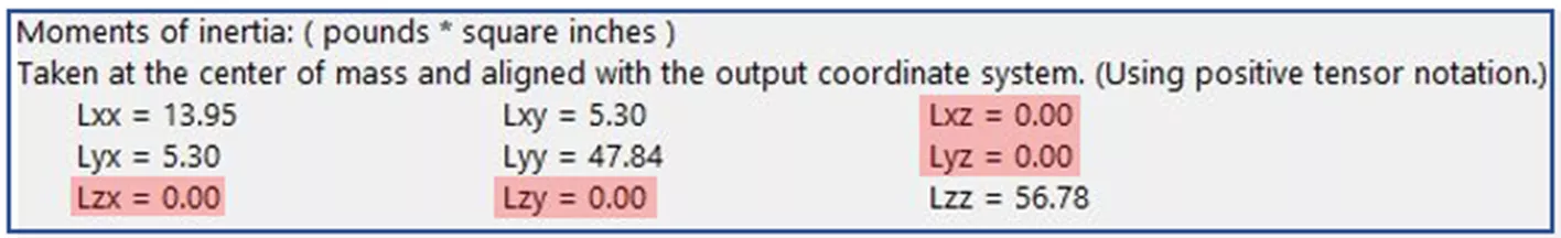
One way of interpreting the matrix notation is: if an object is rotating about the X-axis, then Lxx is its inertia ‘against’ rotation around the X-axis while, simultaneously, Lxz is its inertia ‘against’ rotation around the Z-axis.
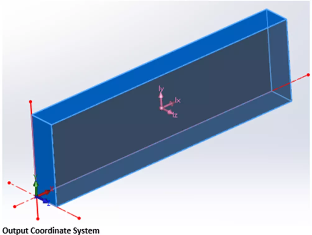
Finally, you’ve probably noticed that Mass Properties also give MOI values about the Output Coordinate System axes. The OCS is the default frame of reference when starting a part, assembly, etc., so its location is dependent on how a model is built.
In the following example, the block was created extruding forward from the default origin (front plane), so its OCS is located at the bottom back-left corner. It’s worth noting that the location of the output coordinate system can easily be changed even after a part is completed and is done through Reference Geometry.
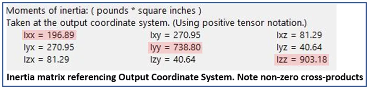
The bottom matrix of numbers in Mass-Properties is calculated by referencing the Output Coordinate System. In this case, it’s easy to envision our example model rotating about the OCS axes, and as we would expect, the Moments of Inertia are much larger. Again, we see the MOI about each axis expressed in the diagonal elements but this time, because the model is not symmetrical about any of the OCS axes, we see non-zero values in all cross-products.
I hope this article cleared up any confusion about the interpretation of Mass Moments of Inertia in SOLIDWORKS. Check out more tips and tricks below.
Additionally, join the GoEngineer Community to participate in discussions, create forum posts, and answer questions from other SOLIDWORKS users.

SOLIDWORKS CAD Cheat Sheet
SHORTCUTS ⋅ MOUSE GESTURES ⋅ HOT KEYS
Our SOLIDWORKS CAD Cheat Sheet, featuring over 90 tips and tricks, will help speed up your process.
More SOLIDWORKS Tutorials
How to Share SOLIDWORKS Files With Anyone
SOLIDWORKS Data Saved to 3DEXPERIENCE - What Happens?
View 3DEXPERIENCE File History from SOLIDWORKS Task Pane
Creating Incremental Numbers in SOLIDWORKS Using Instances to Vary
About James Carlin
James Carlin is a SOLIDWORKS Technical Support Engineer at GoEngineer.
Get our wide array of technical resources delivered right to your inbox.
Unsubscribe at any time.