SOLIDWORKS - Create Advanced Custom Coordinate Systems
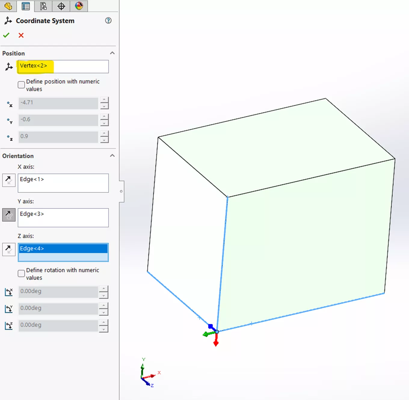
Creating custom coordinate systems in SOLIDWORKS is a fundamental skill used for precise positioning, orientation, downstream analyses, and many others. Typically, defining a coordinate system is straightforward: select a vertex for the origin, then choose model edges or reference geometry to establish the x, y, and z axes in the desired orientation:
Center-Of-Mass Coordinate System
But what if the situation calls for something more advanced? Such as establishing a coordinate system based on a Center of Mass (COM) whose axes don’t align with model edges?
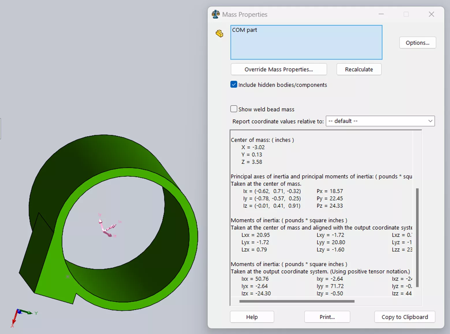
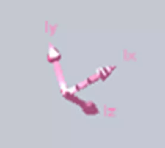
The SOLIDWORKS Mass Properties tool conveniently identifies the exact location of the COM and displays pink-colored axes oriented according to the mass distribution of the model. Unfortunately, however, there is no SOLIDWORKS command to create accurate sketches or reference geometry based on the COM axes.
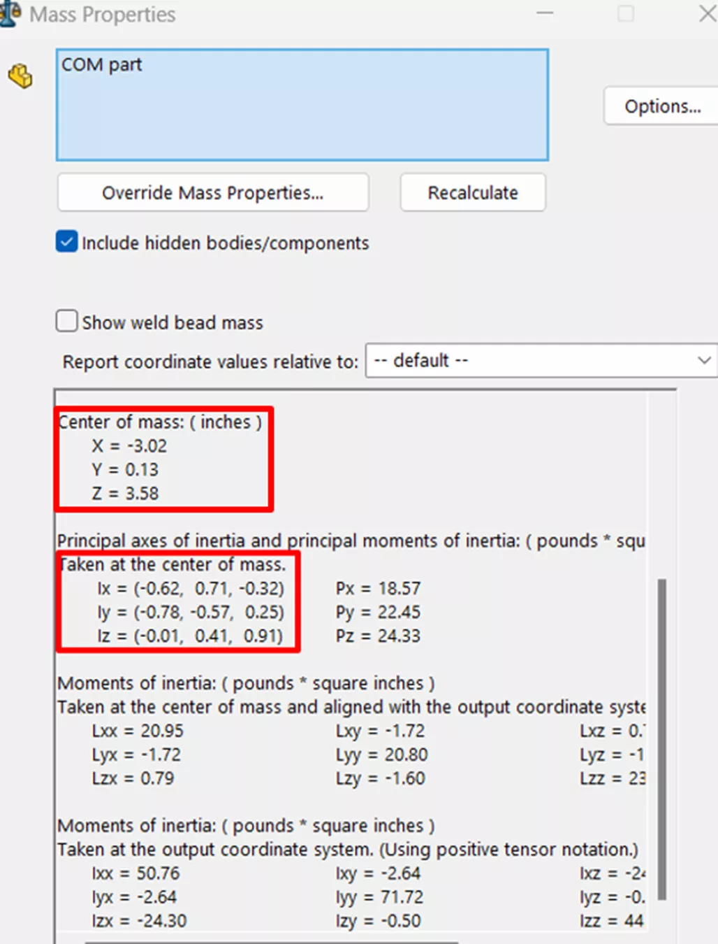
To bridge this gap, you can utilize information in the Mass Properties tool to generate an advanced coordinate system that overlays the COM axes.
The SOLIDWORKS Mass Properties tool displays the COM origin [x, y, z] and a 3x3 matrix defining the orientation of the COM axes: [Ix, Iy, Iz]. This matrix describes the amount the COM axes have rotated away from the principal axes. If you can calculate the angles of rotation, you should then be able to plug them into your new coordinate system.
The angles of rotation are known as Euler Angles and can be hand-calculated, however, the easiest and fastest way to find these is to use an open-source program called “SciLab”. Like SOLIDWORKS, SciLab is also a Dassault Systèmes product dedicated to numerical calculations similar to MatLab. SciLab is free of charge to download.
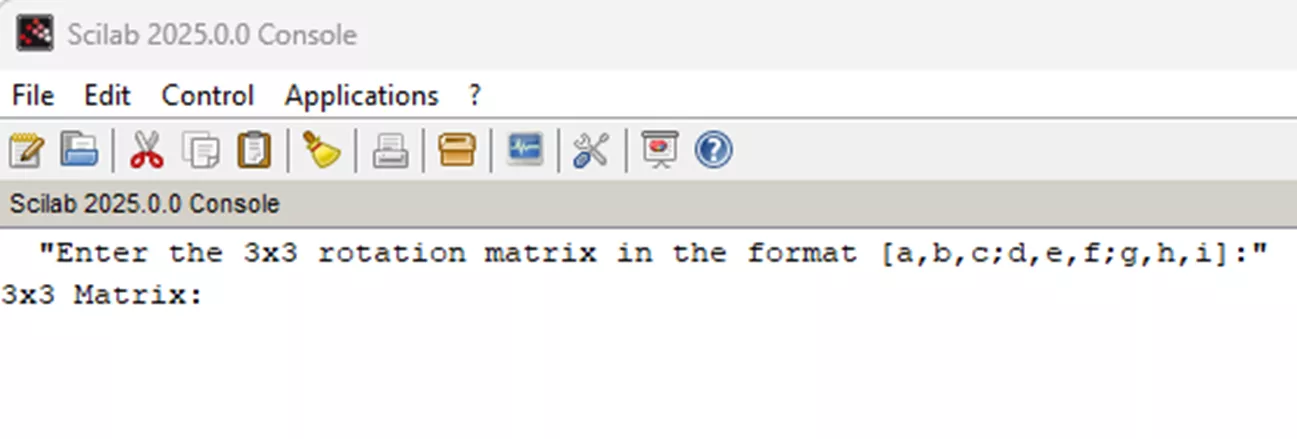
After installing SciLab, download and run the following file named, “Euler Angles”. This will calculate the angles of rotation for you.
When you run the file in SciLab, you should see the following:
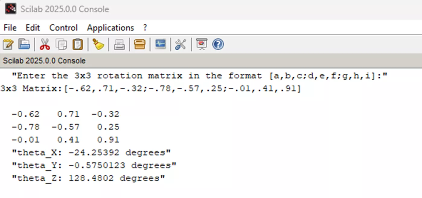
After plugging in the 3x3 COM matrix from the Mass Properties Tool, the program quickly generates the x, y, z angles:
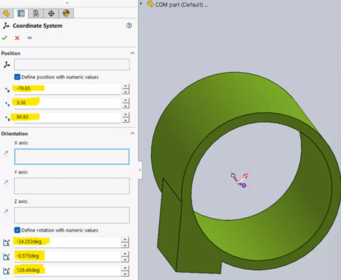
The final step is to input the origin x, y, z coordinates from the Mass Properties tool and calculate Euler Angle angles into the Coordinate System PropertyManager.
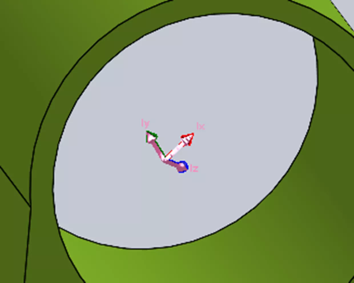
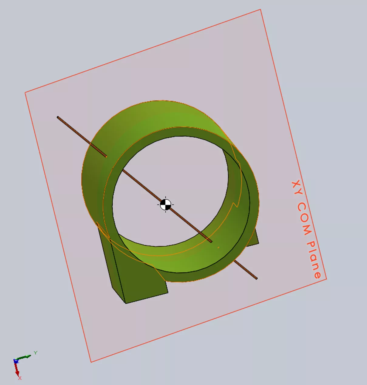
Notice that the new coordinate system aligns perfectly with the COM axes.
Now that you have established your coordinate system, you can create the COM reference geometry you need (e.g., cutting planes, axes of rotation, etc.).
Advanced coordinate systems in SOLIDWORKS unlock a new level of precision for engineers working with complex geometry, motion analysis, or mass-driven behavior. While the software provides powerful tools to visualize mass properties, creating reference geometry aligned with those properties requires a deeper, hands-on approach.
By combining SOLIDWORKS data with external tools like SciLab, users can construct custom coordinate systems that reflect the true physical behavior of their models – enabling smarter design decisions and more accurate analysis.
I hope you found this information useful and put it to the test! Check out more SOLIDWORKS tips and tricks listed below. Additionally, join the GoEngineer Community to participate in the conversation, create forum posts, and answer questions from other SOLIDWORKS users.

SOLIDWORKS CAD Cheat Sheet
SHORTCUTS ⋅ MOUSE GESTURES ⋅ HOT KEYS
Our SOLIDWORKS CAD Cheat Sheet, featuring over 90 tips and tricks, will help speed up your process.
Related Articles
SOLIDWORKS Mass Moments of Inertia Explained
SOLIDWORKS Loft vs Boundary: Key Differences
SOLIDWORKS Sketch Relations Guide
How to Create Sheet Metal Bend Notches in SOLIDWORKS
Creating Incremental Numbers in SOLIDWORKS Using Instances to Vary
About James Carlin
James Carlin is a SOLIDWORKS Technical Support Engineer at GoEngineer.
Get our wide array of technical resources delivered right to your inbox.
Unsubscribe at any time.