How to Create Sheet Metal Bend Notches in SOLIDWORKS
A sheet metal bend notch is a small cut or indentation made at the end of a bend line on a flat sheet metal part. This is designed to help press brake operators to position the material on a press brake machine for a more dialed-in approach. Mostly being used as a visual guide throughout the bending process. This tutorial explains how to create these sheet metal bend notches in SOLIDWORKS.
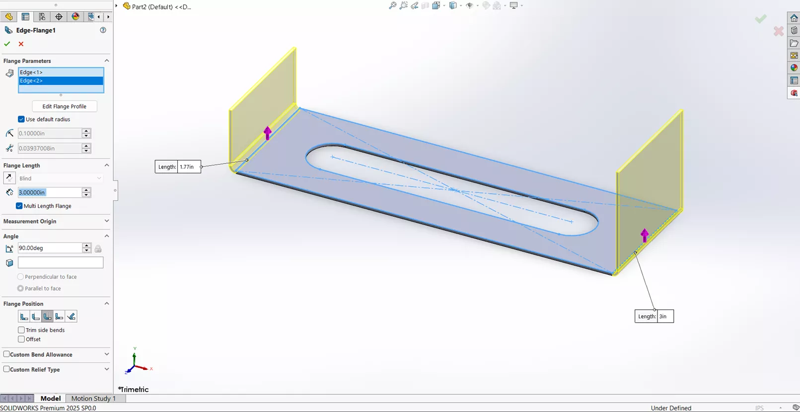
- In SOLIDWORKS, open or create a sheet metal part with at least one bend. In this example, there are two bends.
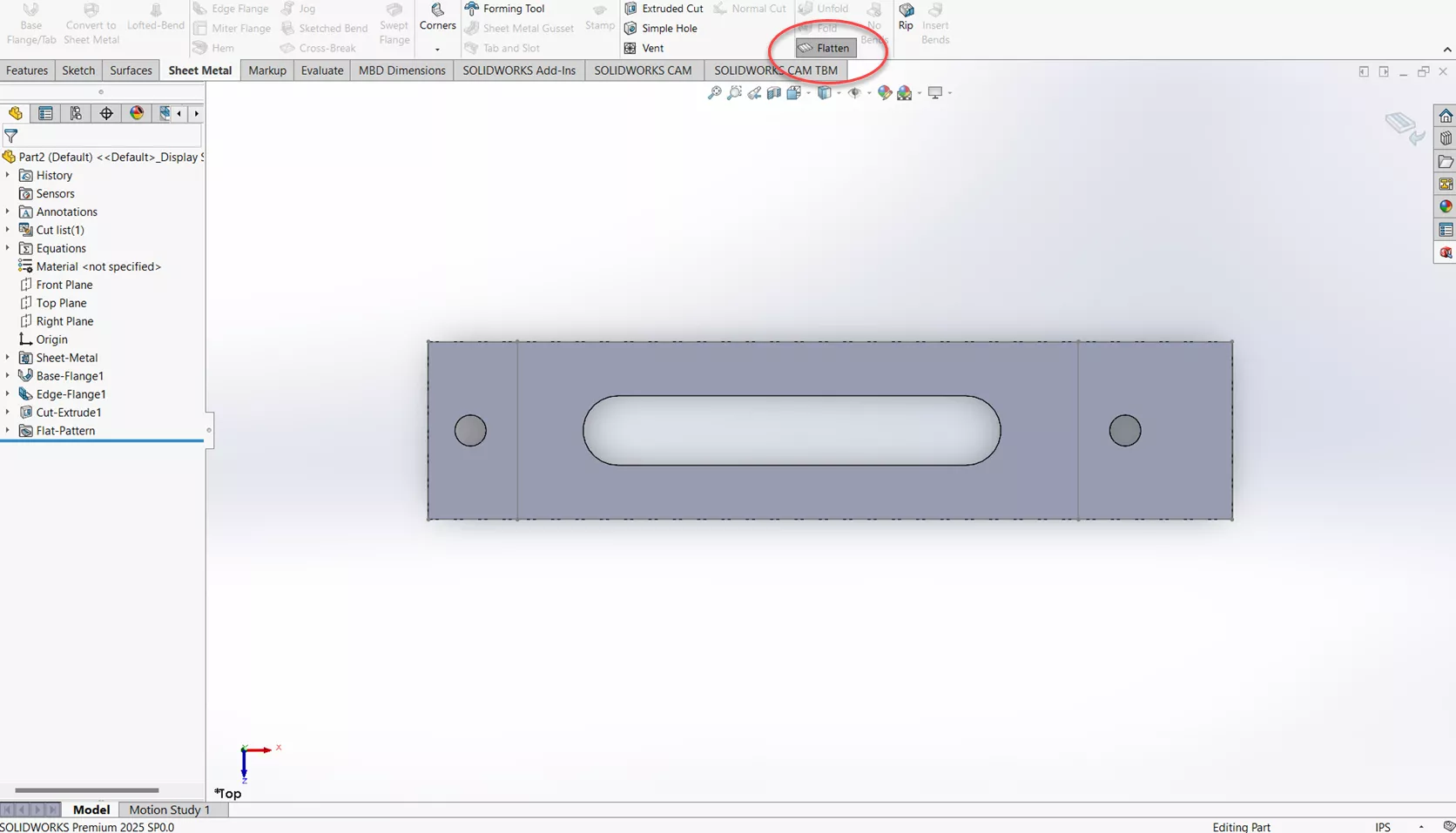
- Flatten the part using the Flatten tool.
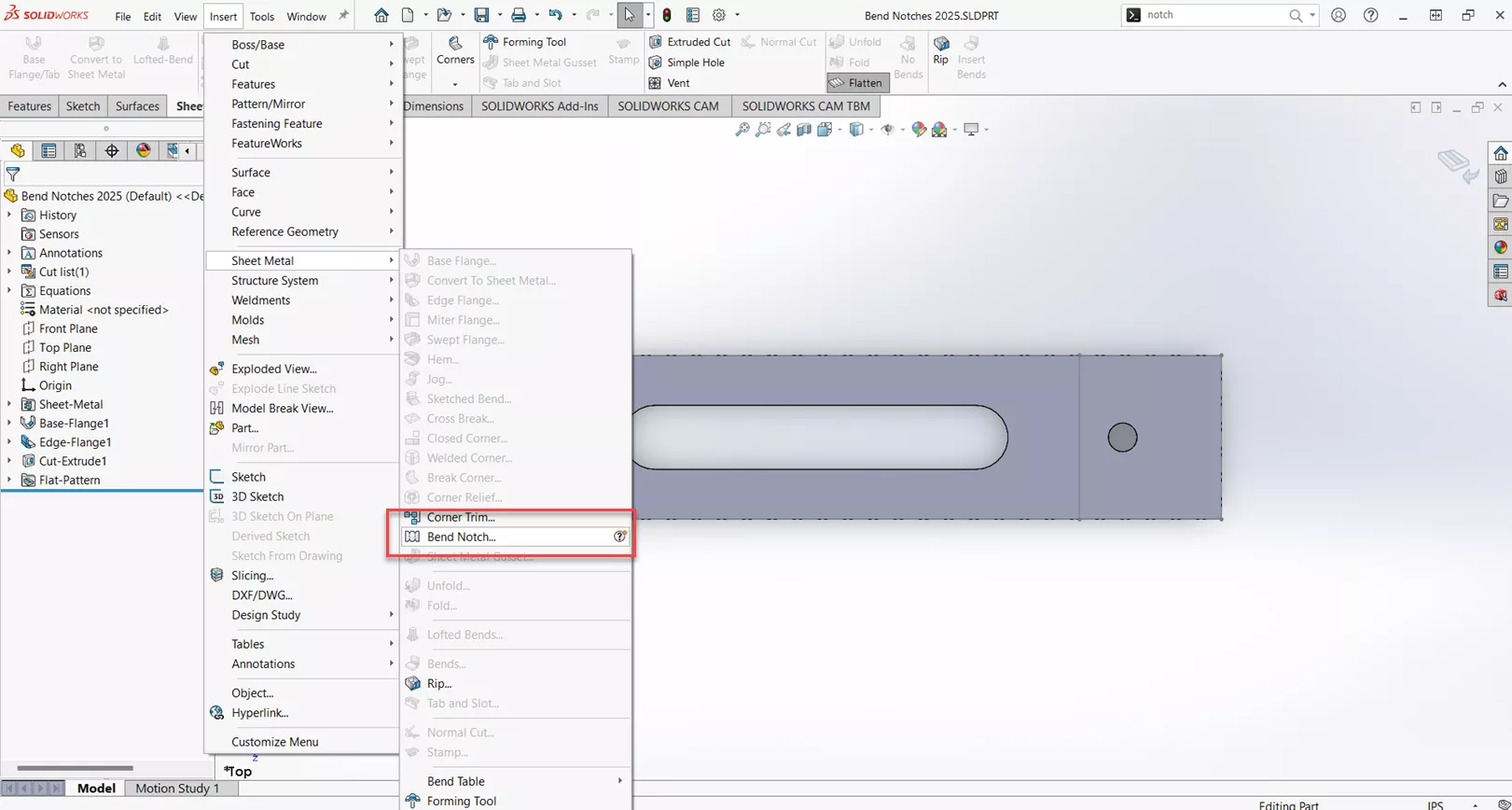
- Navigate to Insert > Sheet Metal > Bend Notch.
- This will bring up the PropertyManager screen for Bend Notches. Let's start by collecting all Bends.
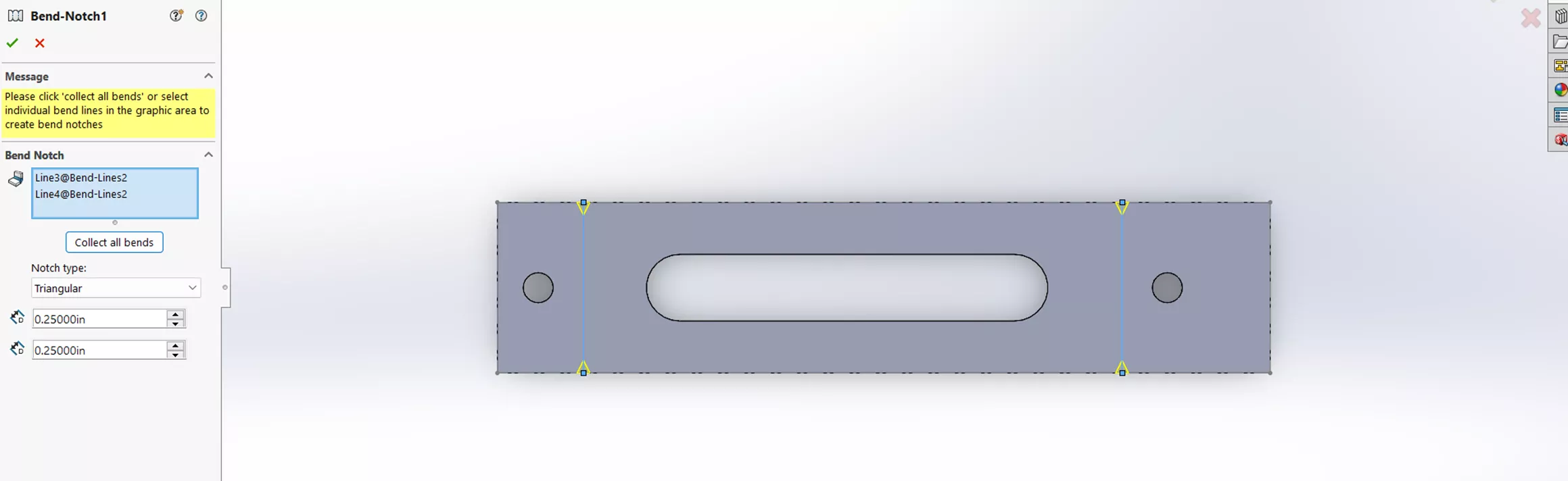
- For Notch Type, you are presented with three options: Triangular, Circular, and Rectangle. For this example, let's use circular with a radius of .09375. Select the green check mark.
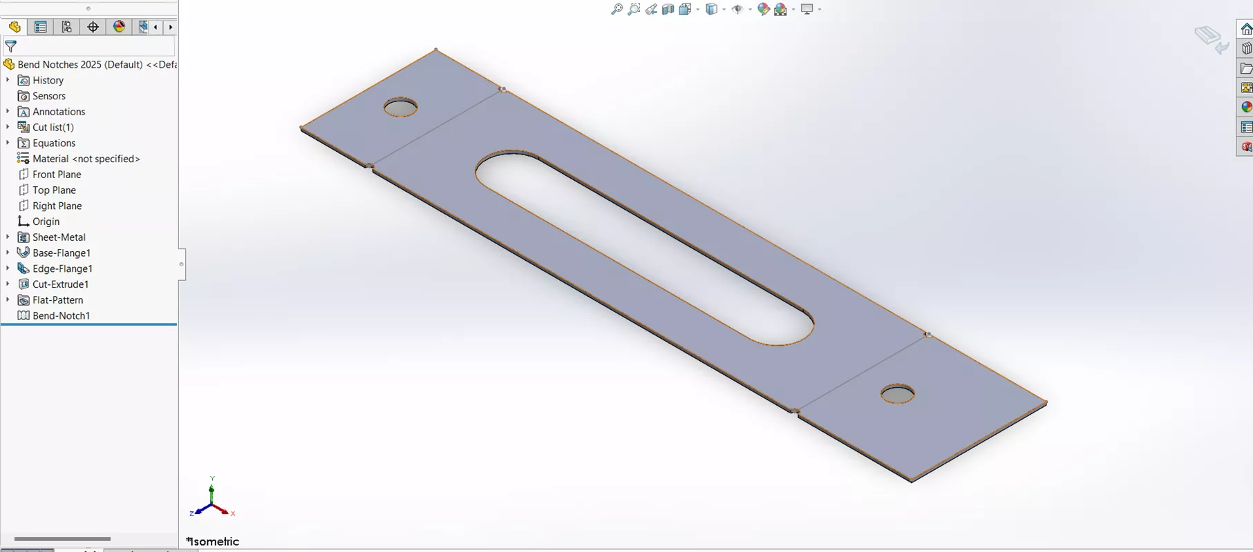
It is important to note that the Bend Notches will only show in the Flatten State.
Corner Relief
When designing sheet metal parts, look out for potential deformation and tearing. To avoid this, you can add Corner Reliefs. Below are some techniques to consider.
- To start, make a Base Flange with four edge flanges of equal size.
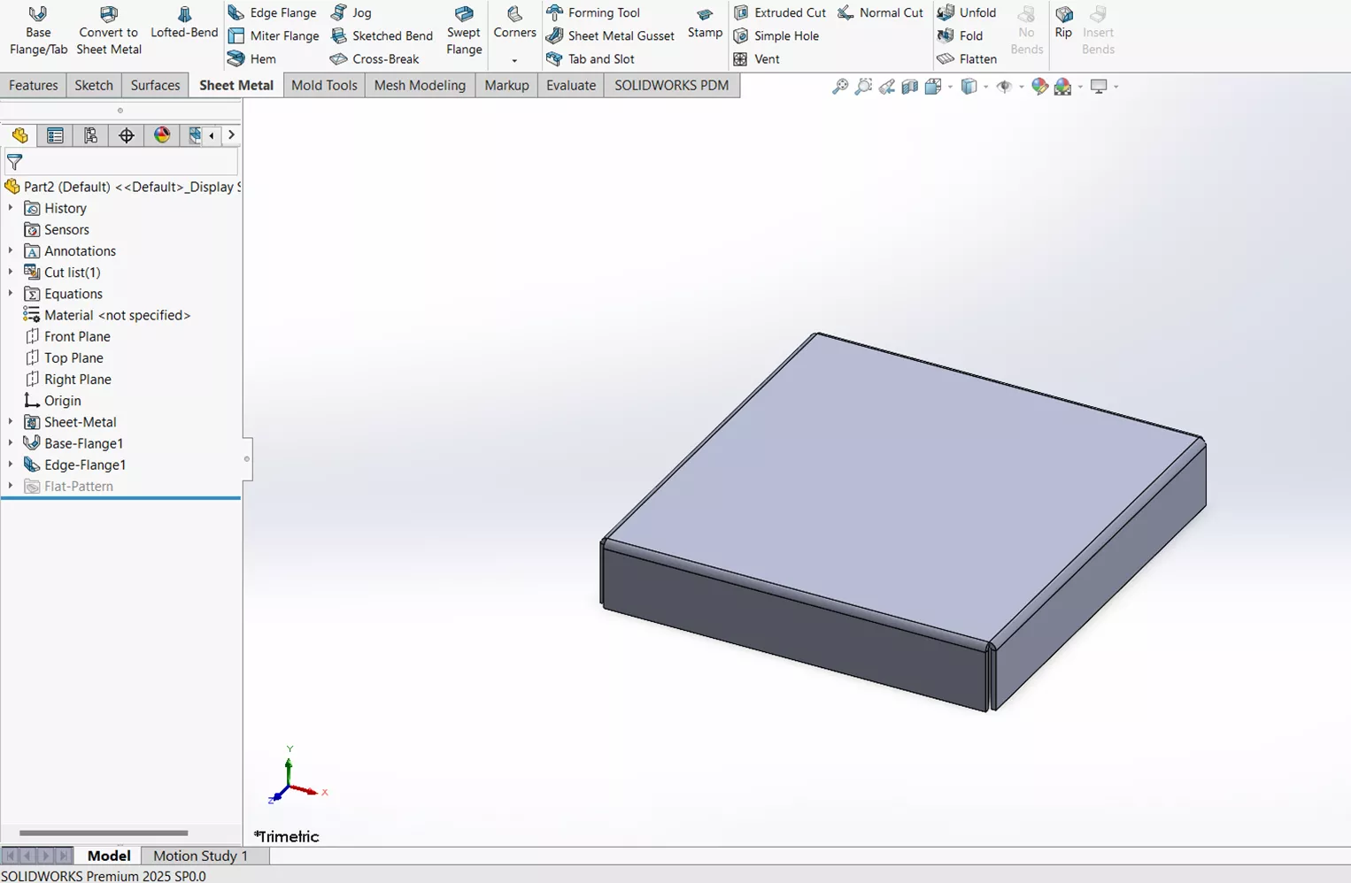
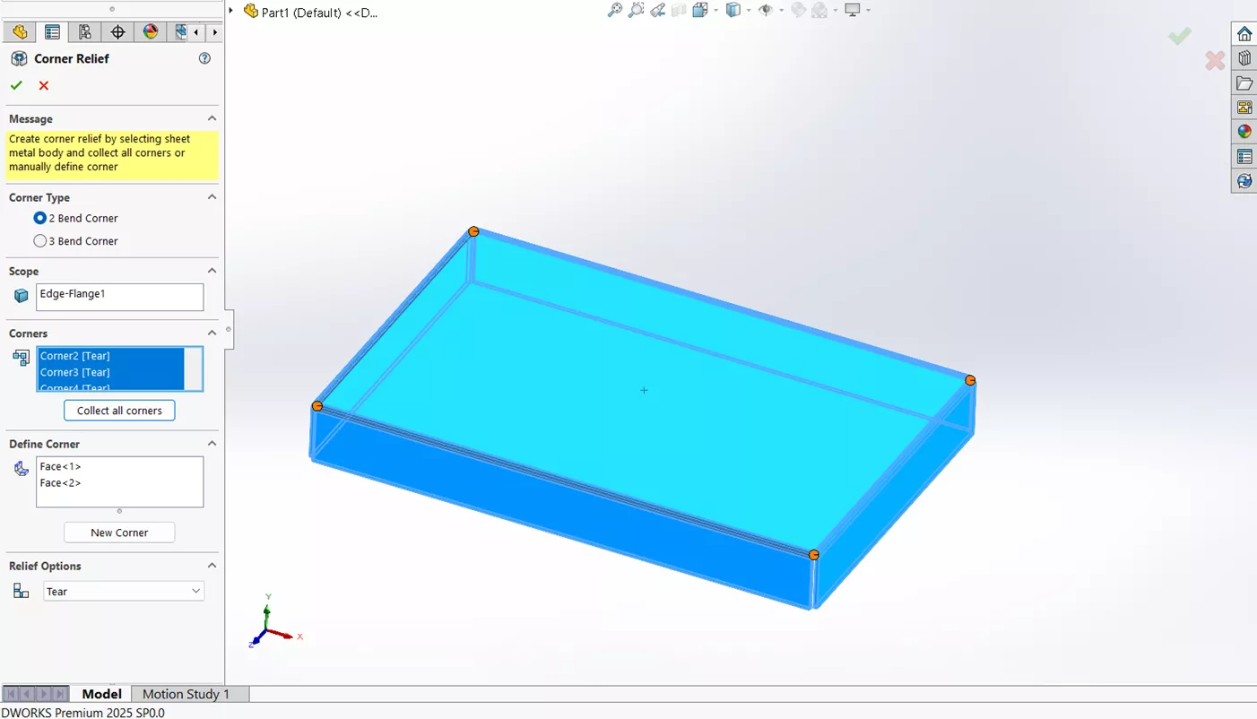
- Select Corners from the CommandManager then Corner Relief. What is incredible about this specific feature is that if the sheet metal part is made correctly, it will automatically pick the corners for you.
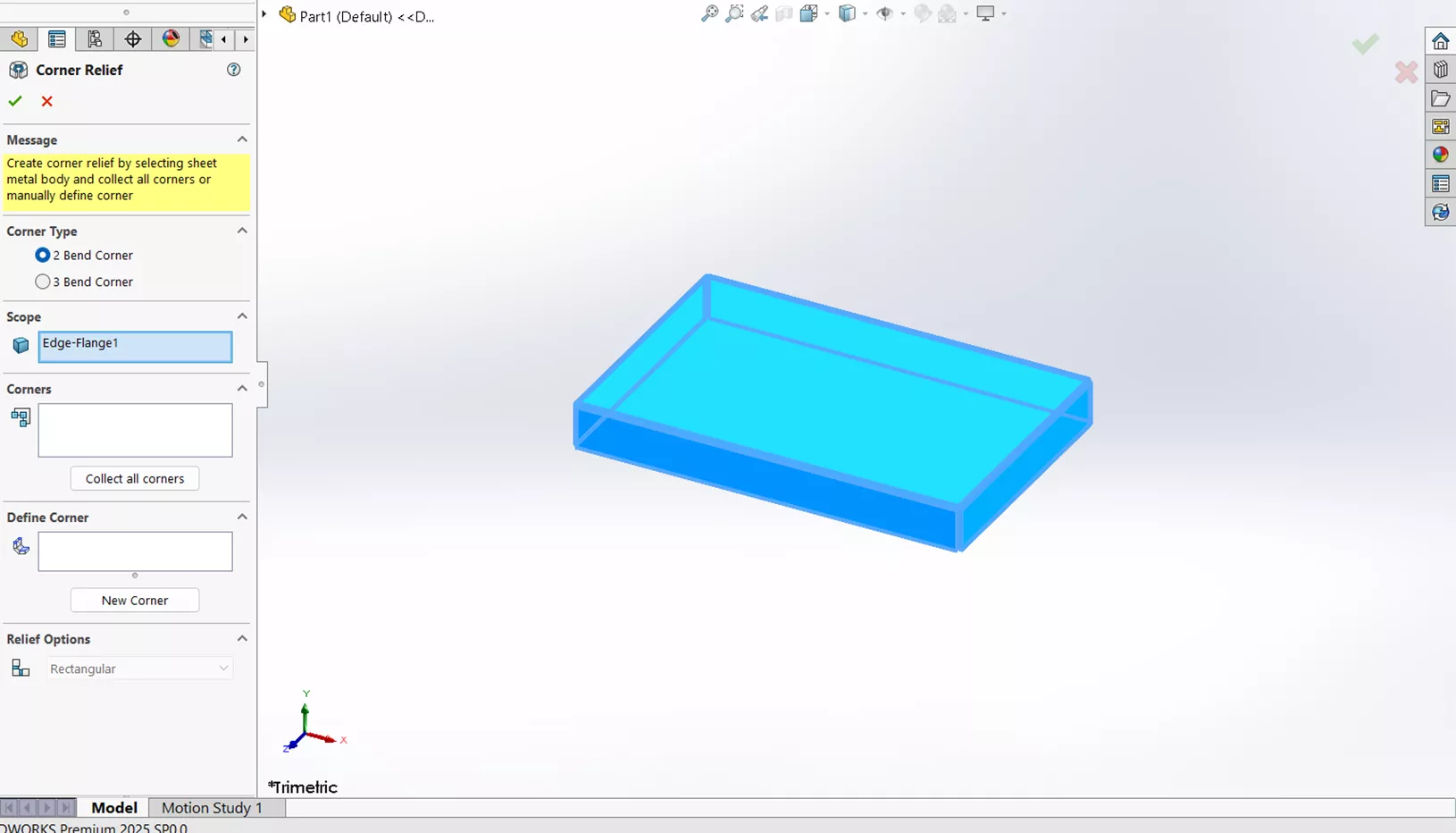
- There are two types of Corner Reliefs: 2 Bend Corner and 3 Bend Corner. A 2 Bend Corner Relief is used when two sheet metal bends meet and create a corner. A 3 Bend Corner Relief is used where three bends meet at a common point, creating a 3-sided corner. For this particular example, I will select the default setting with 2 Bend Corner.
- Inside the white box labeled Corners, select Collect all Corners.
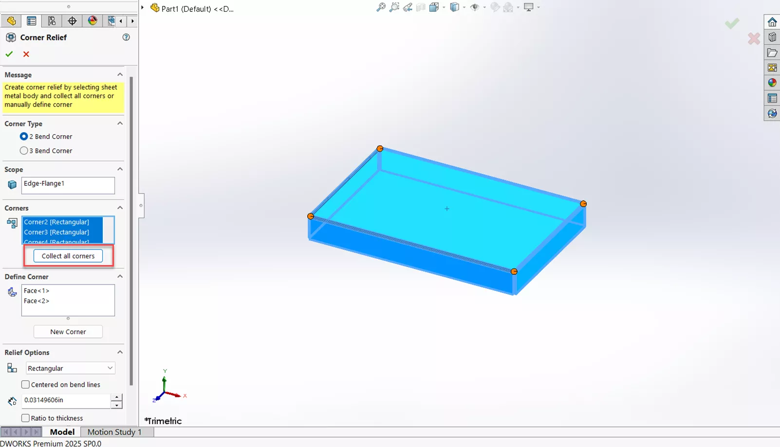
- Now it's time to customize your relief options (depending on your application. These options are: Rectangular, Circular, Tear, Obround, and constant width.
- Rectangular Settings: Centered on bend lines, slot length, ratio to thickness, tangent to bend, add filleted corners, and corner fillets.
- Circular Settings: Centered on bend lines, slot width, ratio to thickness, and tangent to bend.
- Tear Settings: No relief options
- Obround Settings: Centered on bend lines, slot length, slot width, and ratio to thickness.
- Constant width: No relief options.
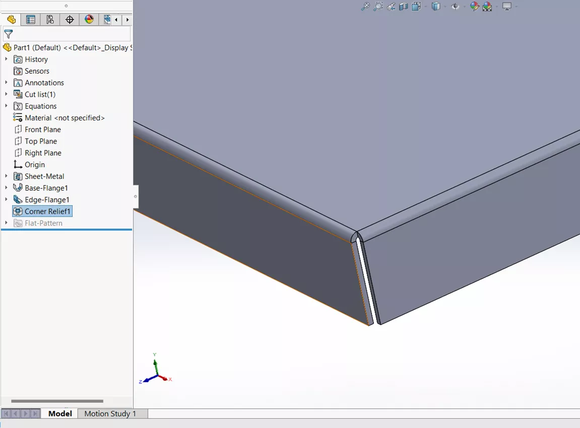
- For this example, I will use the Tear Relief. After selecting this, notice in the Corners box, that Rectangular has been replaced with Tear.
- Click the check mark and you should now have your corner relief.
I hope you found this Sheet Metal tutorial helpful. Check out more tips and tricks below. Additionally, join the GoEngineer Community to participate in discussions, create forum posts, and answer questions from other SOLIDWORKS users.
SOLIDWORKS Sheet Metal Training

Want to become an expert? Learn to build stand-alone sheet metal parts and covert conventional parts in our Professional SOLIDWORKS Sheet Metal training course.
Related Articles
SOLIDWORKS 2025 Sheet Metal - What's New
SOLIDWORKS Sheet Metal Sketched Bend Tutorial
SOLIDWORKS Convert to Sheet Metal Command Explained
SOLIDWORKS Sheet Metal Tab and Slot Tutorial
About Brandon Lenoir
Brandon is a SOLIDWORKS Technical Support Engineer at GoEngineer.
Get our wide array of technical resources delivered right to your inbox.
Unsubscribe at any time.