SOLIDWORKS Sheet Metal Sketched Bend Tutorial
In SOLIDWORKS, a Sheet Metal Sketched Bend is a method of adding a bend to a sheet metal part relative to a line in a special sketch. This special sketch is created within the Sketched Bend command.
Sheet Metal Sketched Bend can be used on any sheet metal part. It is particularly handy when you need to work from a known flat pattern. The beauty of the Sheet Metal Sketched Bend is that it follows a bend line that we sketch versus an existing edge on the part.
Adding A Sheet Metal Sketched Bend Is as Simple As:
- Select a face on an existing sheet metal part to add the sketch.
- Sketch the bend line.
- Select the face that is to remain fixed.
- Define bend parameters (angle, position relative to the sketch line, bed radius)
How to add a Sheet Metal Sketched Bend
In the following example, we will look at how to add a Sheet Metal Sketched Bend in SOLIDWORKS. We are working from a flat pattern that is being driven by tooling constraints. In other words, the cutting die is much too expensive to change, and we need our formed part to adapt to using this blank.
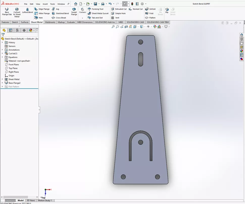
Add the Sketched Bend by selecting the Sketched Bend button in the Sheet Metal menu.
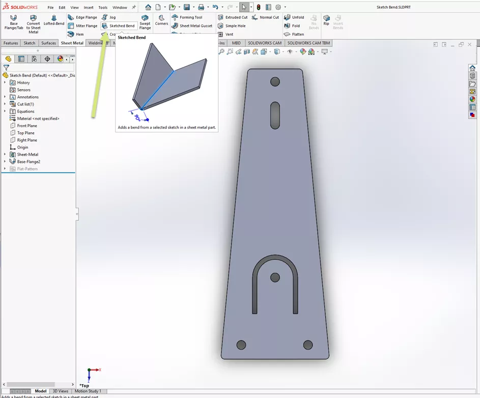
This opens the Sketched Bend dialog that prompts us for a face to sketch on. I will select this top face.
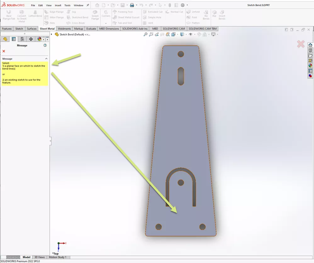
Now we are in sketch mode within the Sketched Bend command. Here, we will sketch a line that will act as the reference line to place the bend. We are going to sketch two lines that are colinear and are running at an odd angle across the part. The sketch line does not need to be perpendicular or parallel to any edge of the part - it can be at any desired angle.
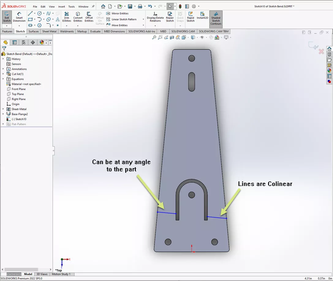
When exiting the sketch, we can see the Bend Parameters portion of the dialog. From here, we need to define what portion will remain fixed. I selected inside the part contour below the lines we sketched.
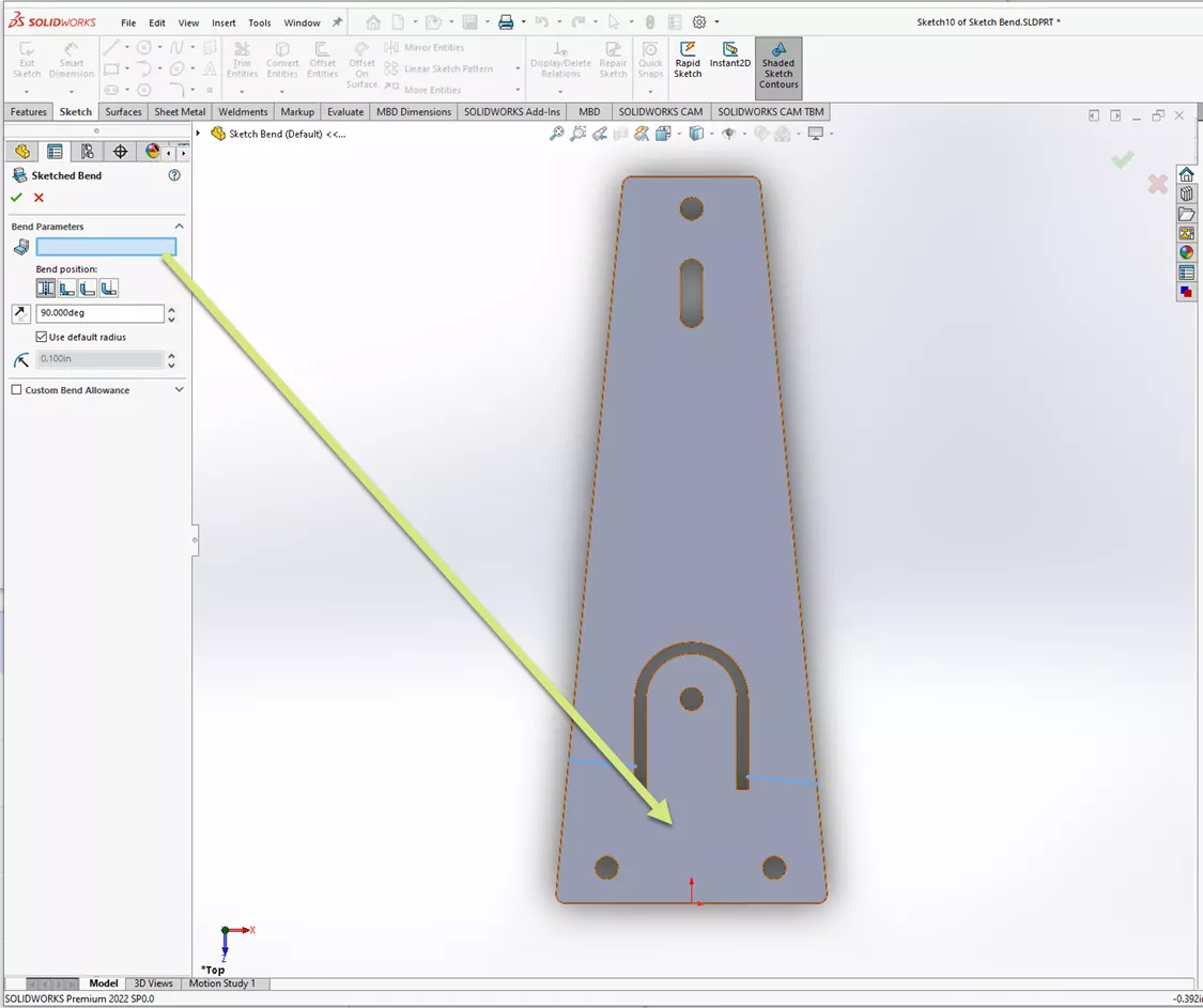
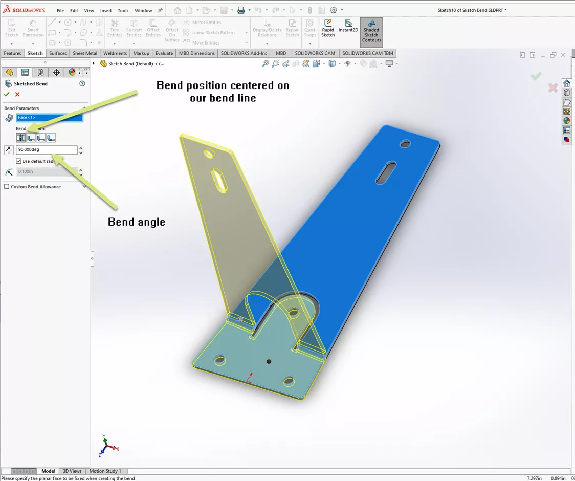
Once the fixed face has been defined, we see a preview of the bend. The bend is currently centered on the lines we sketched and is 90 degrees to the fixed face.
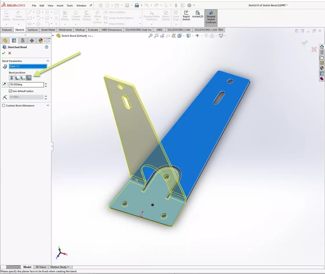
In this case, we do not want the bend centered on the sketched lines, so we will select the option to bend offset from the lines.
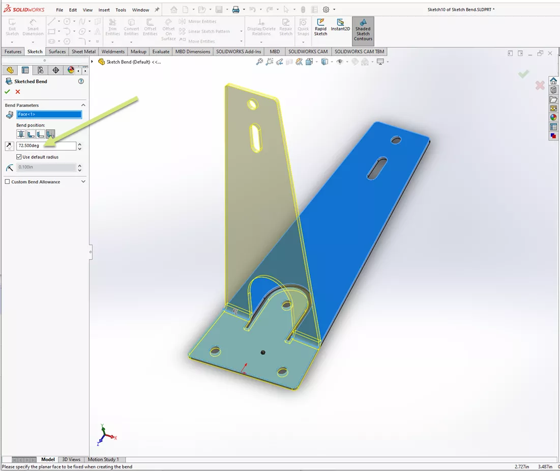
Next, we will adjust the bend angle from 90 degrees to 72.5 degrees. Optionally, we can adjust the bend radius in this dialog if we are unhappy with the default setting.
After hitting the green check mark to confirm our settings, we can see our bent part. Notice how it is bent along the two colinear sketched lines leaving the center tab unbent.
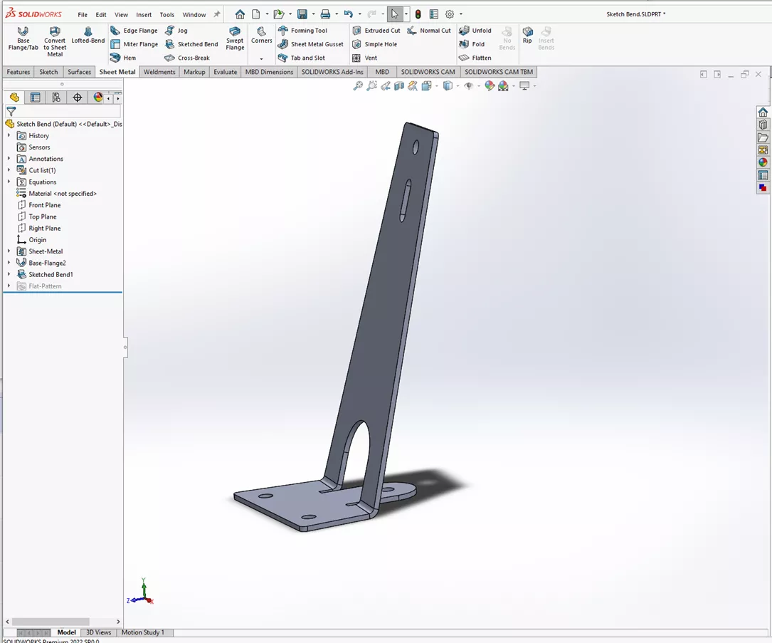
That is the simple trick to creating complex seeming bends with a sketch bend.
I hope you found this tutorial explaining Sheet Metal Sketched Bend in SOLIDWORKS helpful. Check out more tips and tricks listed below. Additionally, join the GoEngineer Community to participate in the conversation, create forum posts, and answer questions from other SOLIDWORKS users.
Want to take your SOLIDWORKS skills to the next level? Enroll in the official SOLIDWORKS Sheet Metal training course. Both online and in-person classes are available.
SOLIDWORKS CAD Cheat Sheet
SHORTCUTS ⋅ MOUSE GESTURES ⋅ HOT KEYS
Our SOLIDWORKS CAD Cheat Sheet, featuring over 90 tips and tricks, will help speed up your process.
More SOLIDWORKS Tutorials
How to Add a Watermark Note in SOLIDWORKS
How to Create Text Around a Circle in SOLIDWORKS
Work Smart with SOLIDWORKS Smart Components
SOLIDWORKS Costing: Sheet Metal Parts

About Chris Geringer
Chris is a Technical Support Engineer at GoEngineer. When Chris isn't assisting customers, he enjoys biking and volunteering with a group that preserves vintage aircraft.
Get our wide array of technical resources delivered right to your inbox.
Unsubscribe at any time.
