SOLIDWORKS Loft vs Boundary: Key Differences
When designing complex parts in SOLIDWORKS, the Loft and Boundary commands are invaluable tools for creating organic shapes and surfaces. While both commands share similarities in creating Boss, Cut, and Surface features, they each offer distinct capabilities that you can leverage for different scenarios. In this blog, we discuss the key differences between the loft and boundary commands in SOLIDWORKS.
Loft vs Boundary PropertyManager Comparison
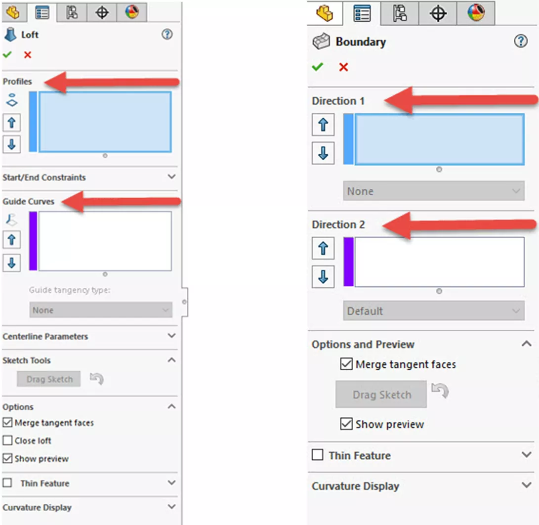
In the Loft PropertyManager, you’ll find options for Profiles, Start/End Constraints, and Guide Curves. These controls allow you to influence the shape of the loft by adjusting how the profiles blend together, particularly at the start and end of the loft (outer profiles).
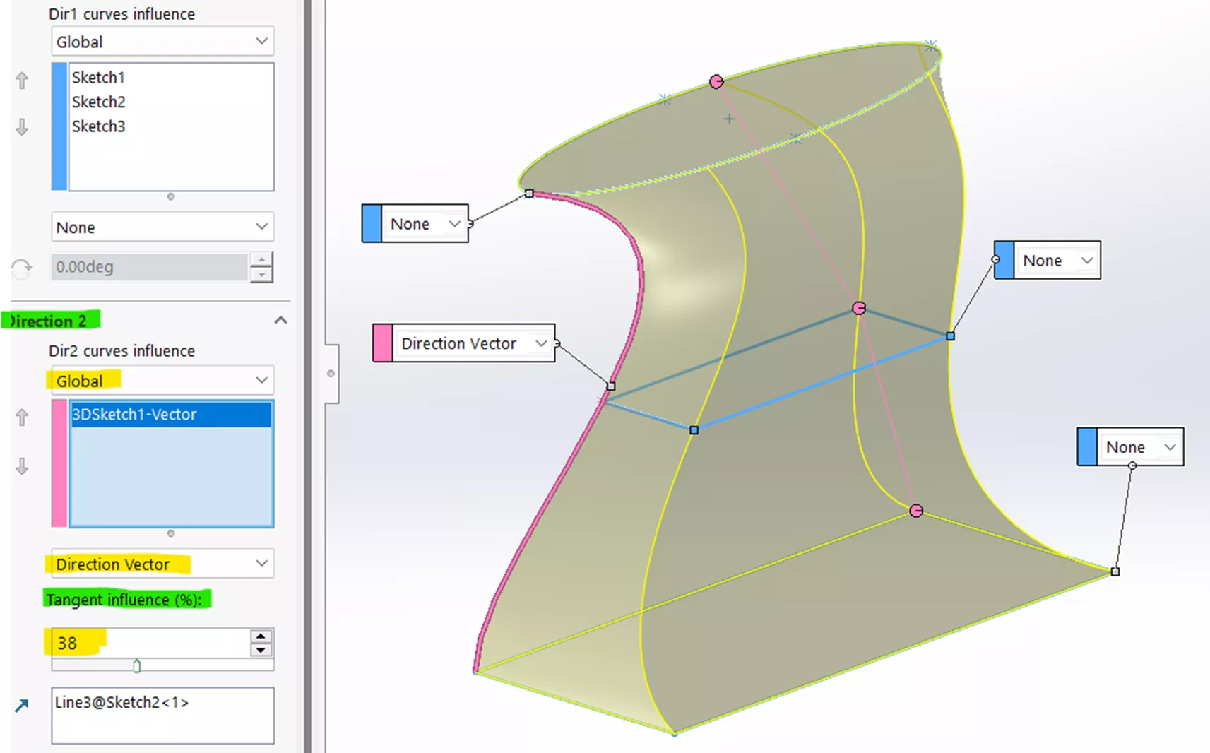
The Boundary PropertyManager offers Direction 1 and Direction 2 controls, allowing you to manage the flow of the geometry in multiple directions. This gives you more precise control over how all profiles blend together and is especially useful when dealing with complex shapes. Note that Guide Curves and Direction 2 are essentially synonymous.
A key difference between these tools lies in their constraints. In the Loft feature, you have control over tangency magnitude and direction at the start and end profiles, however, no direct control over the tangency for profiles that happen to lie between the start and end profiles.
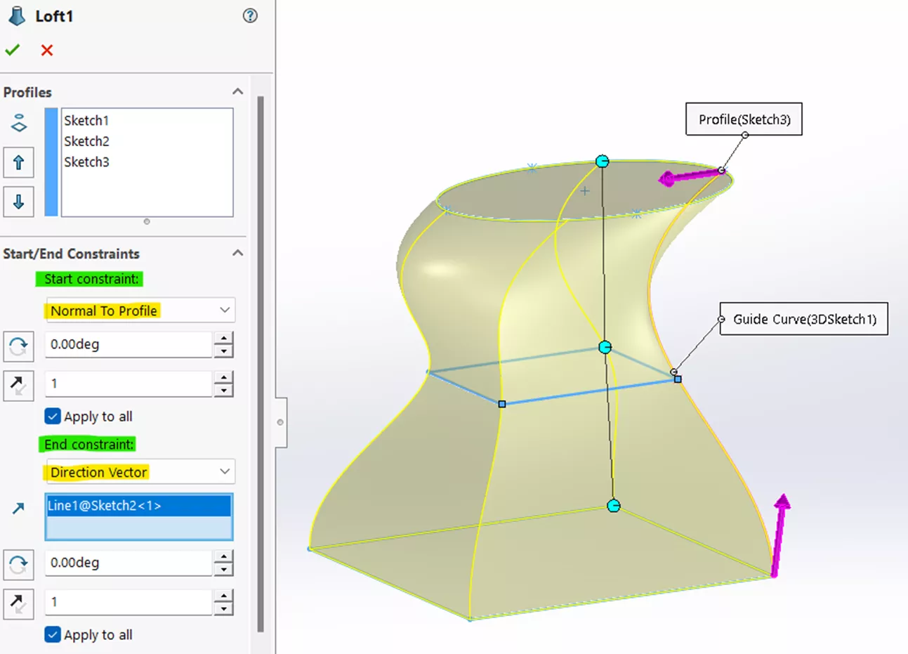
The Boundary feature does allow the ability to control tangency across multiple profiles in one or two directions, offering a higher level of control over the curvature and overall shape.
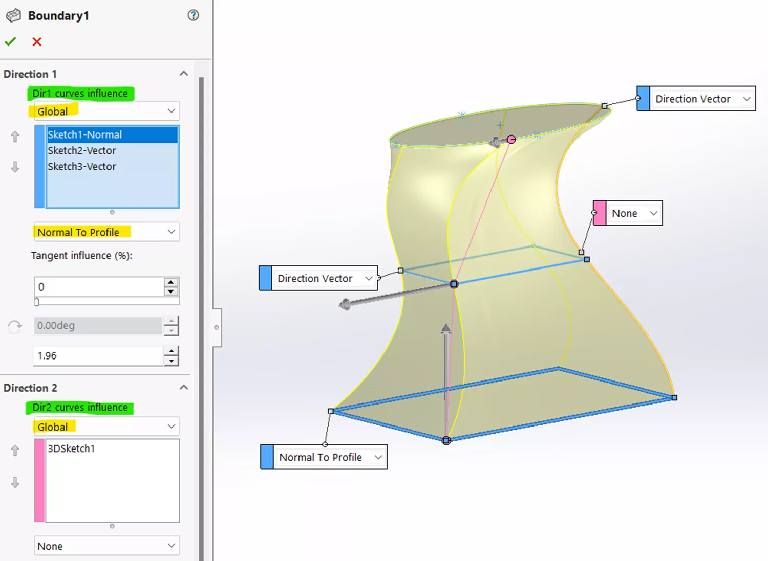
Guide Curves
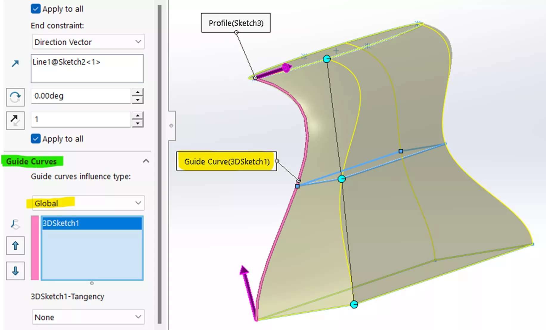
When Guide Curves are used, the Loft feature allows you to adjust the influence and tangency type along these curves. Guide Curves provide additional control over the shape of the Loft, allowing for more complex curvatures and twists.
In the Boundary feature, adding sketches in Direction 2 provides the same kind of control, but with more flexibility in managing the curve’s influence on the overall shape.
Simplicity vs. Complexity
Lofts are well-suited for creating organic shapes and/or cuts between two relatively simple profiles. This includes shapes like cylinders, cones, or even more complex forms as long as the transition between them is straightforward. If your design involves simple shapes between two profiles, go with the Loft.
For more complex shapes and cuts with multiple profiles and curves, sharp corners, intricate transitions, and precise tangency requirements, a Boundary is the better choice.
In summary, while the Loft and Boundary features in SOLIDWORKS share some overlap in functionality, they each have unique strengths. Both are essential tools for creating complex shapes, but the best choice often depends on the specific needs of your design.
Loft is particularly effective for centerline function and automatic section addition while Boundary offers greater versatility with curvature continuity and connectors, making it the preferred choice for many users. By understanding the nuances of both features, you can select the most appropriate tool for each design scenario and avoid unnecessary trial and error.
I hope you found this article explaining the differences between boundary and loft features in SOLIDWORKS helpful. Check out more tips below. Additionally, join the GoEngineer Community to participate in the conversation, create forum posts, and answer questions from other SOLIDWORKS users.

SOLIDWORKS CAD Cheat Sheet
SHORTCUTS ⋅ MOUSE GESTURES ⋅ HOT KEYS
Our SOLIDWORKS CAD Cheat Sheet, featuring over 90 tips and tricks, will help speed up your process.
Learn More
Managing SOLIDWORKS Loft Connectors
SOLIDWORKS Surfacing - Boundary Surfacing Equal Curvature
SOLIDWORKS Tutorial - Boundary Trim by Direction
About James Carlin
James Carlin is a SOLIDWORKS Technical Support Engineer at GoEngineer.
Get our wide array of technical resources delivered right to your inbox.
Unsubscribe at any time.