SOLIDWORKS Sketch Relations Guide
In SOLIDWORKS, a sketch is typically your starting point for any design. You begin by adding sketch entities and defining them using two methods: Dimensions and Relations. The Dimension tool allows you to assign numerical values to sketch entities. Relations are relationships between one or more entities that force a specific interaction. Many of us have encountered a relation icon that we did not recognize or attempted to make a relation that would not show up on the available list. In this guide, we will cover all SOLIDWORKS Sketch Relations, including what they look like, what is required to make them, and how they interact with your sketch entities.
SOLIDWORKS Sketch Relations
This guide will cover the following Sketch Relations:
- Horizontal & Vertical
- Collinear
- Coradial
- Perpendicular
- Parallel
- ParallelYZ
- ParallelZX
- Along Axis
- Tangent
- Concentric
- Midpoint
- Intersection
- Coincident
- Equal
- Equal Curvature
- Symmetric
- Fix
- Fix Slot
- Pierce
- Merge Points
- Doubled Distance
- Equal Slots
- On Edge
- On Plane
- On Surface
- Tangent to Face
- Torsion Continuity
Horizontal and Vertical
The most basic and commonly used relations are the Horizontal and Vertical, which can be applied to one or more lines or two points. When this relation is added to a line, it will either become vertical or horizontal in reference to the current sketch space. When added to points, they will be aligned vertically or horizontally.
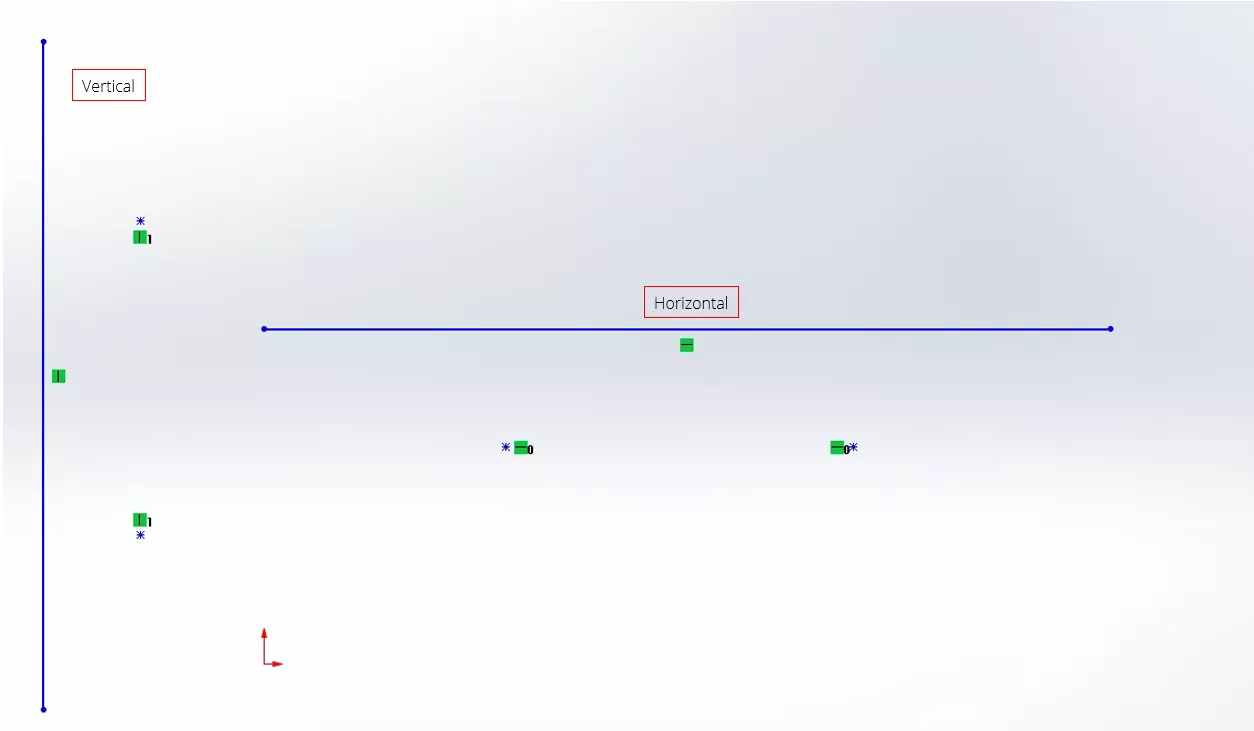
Figure 1: Horizontal and Vertical Relations Added to a Sketch Entity
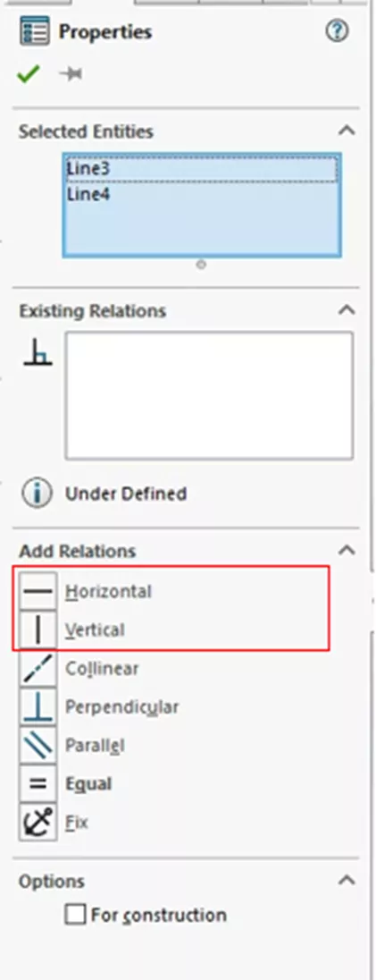
Figure 2: Location in the Properties Menu
ColLinear
Collinear Relations require two or more lines. When added, these two lines will lie on the same infinite line.
Note: The lines do not have to be touching in any way and can be oriented in any direction.
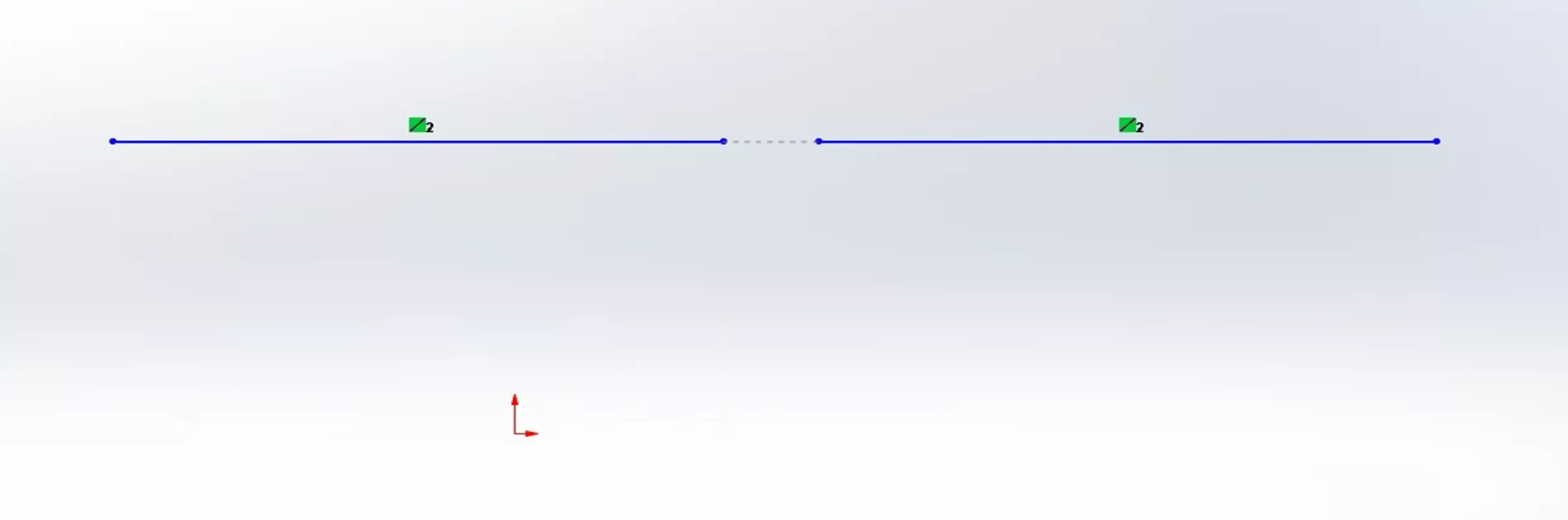
Figure 3: Collinear Relations
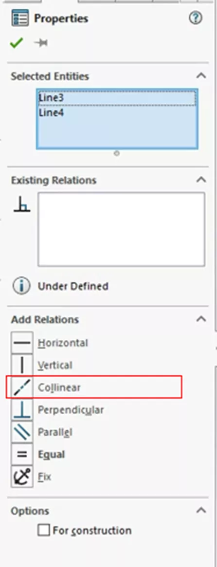
Figure 4: Add Collinear Relations
Coradial
Coradial Relations are added to two or more arcs. When added, the items share a center point and have the same radius.
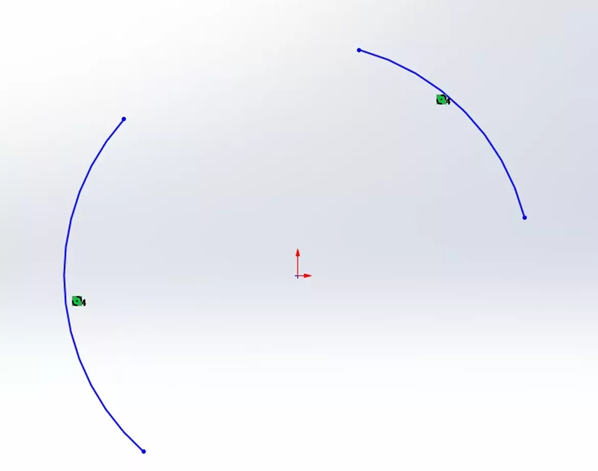
Figure 5: Coradial Relations
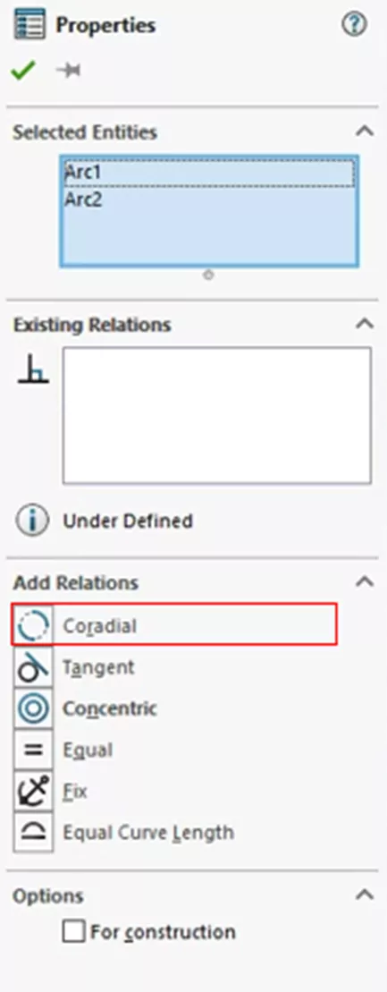
Figure 6: Add Coradial Relations in SOLIDWORKS
Perpendicular
Perpendicular Relations are made from two lines. When added, the two items will be angled 90° (perpendicular) to each other.
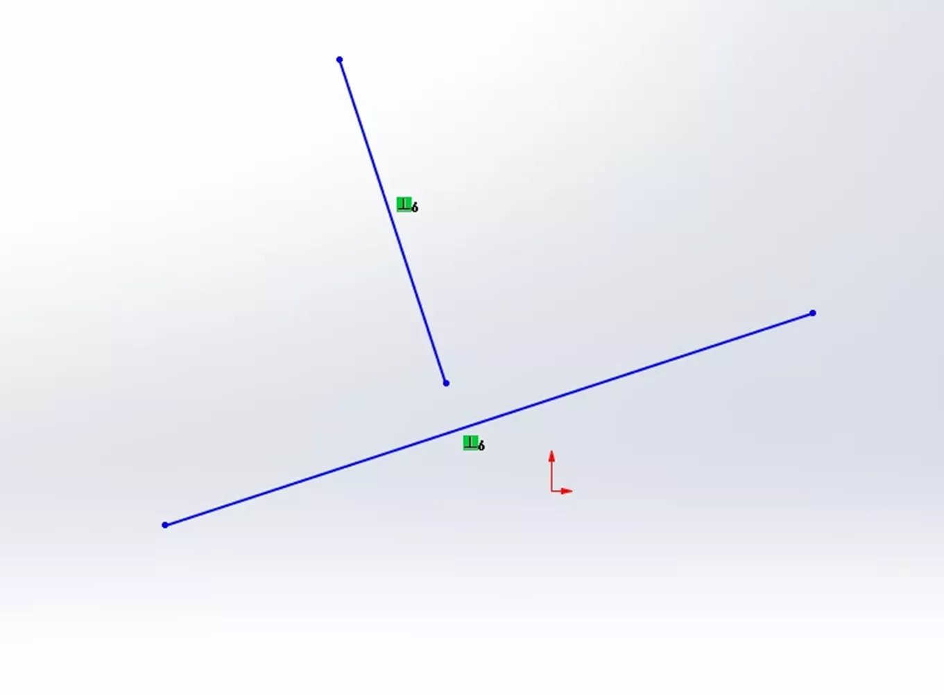
Figure 7: Perpendicular Relation
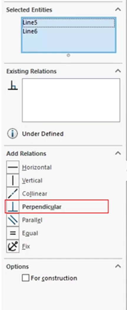
Figure 8: Add Perpendicular Relations
Parallel
Parallel Relations can be made from a number of entities, such as from two lines, a line and a plane, or a planar surface when used inside a 3D sketch. When this relation is added between two lines, the two lines will become parallel to each other. When added to a line and some planar object the line will become parallel to the plane.
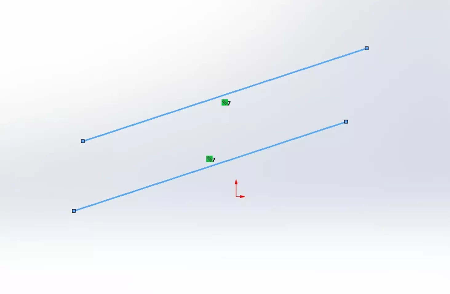
Figure 9: Parallel Relation
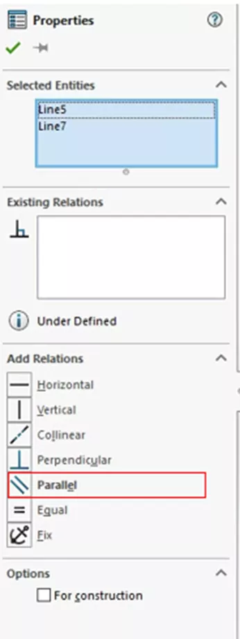
Figure 10: Add Parallel Relations
ParallelYZ
The ParallelYZ Relation is different from those previously mentioned because it can only be applied inside of a 3D sketch. It also differs in the fact that the relation is not created in reference to a Sketch space. When creating a ParallelYZ Relation, draw a line and select the line and one of the default reference planes (such as Front, Top, or Right planes). This will bring up the same selection menu you are used to with the option to select the ParallelYZ Relation.
Note: A green relation icon is not added unless the line is selected. However, notice that, as you rotate your sketch entities and observe the reference triad at the bottom left of your screen, the Sketch entities lie on the YZ plane.
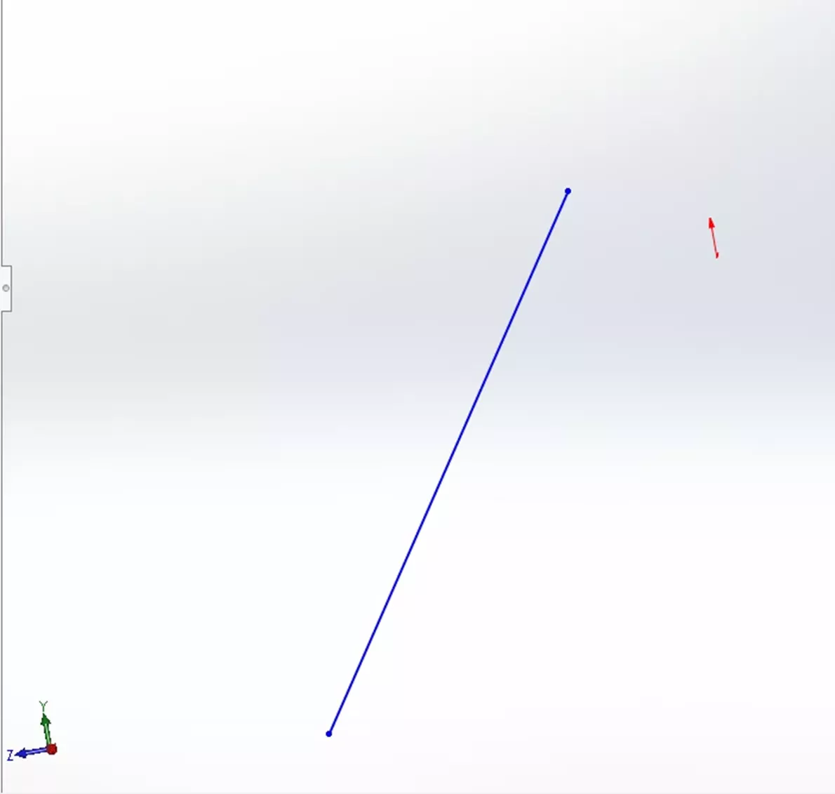
Figure 11: ParallelYZ Relation
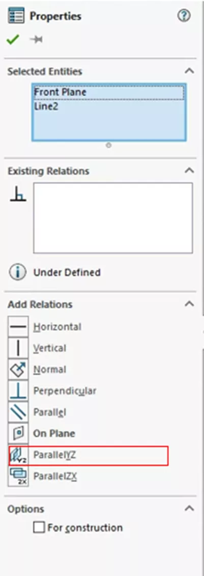
Figure 12: Add ParallelYZ Relation
ParallelZX
ParallelZX is nearly identical to ParallelYZ, being created in the same way and using the same process. The only difference is which plane the line will be parallel to.
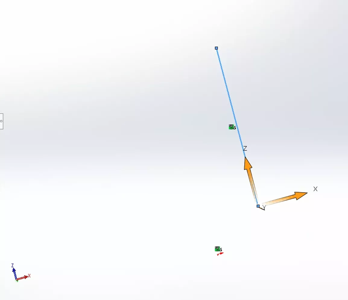
Figure 13: ParallelZX Relation
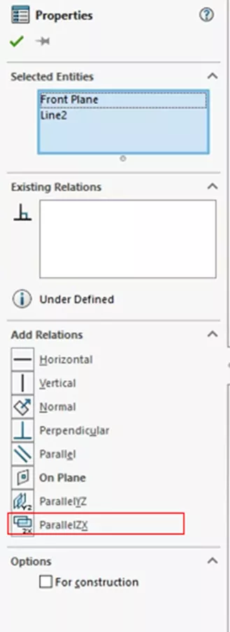
Figure 14: Add ParallelZX Relation
Along Axis
Along Axis is a unique relation made in 3D sketches and only requires a single line. This line is then aligned parallel to the global axis specified. You can create Along X, Along Y, and Along Z relations.
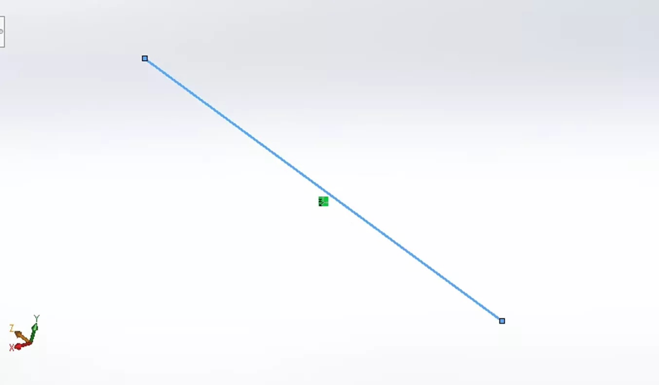
Figure 15: Along Z Relation
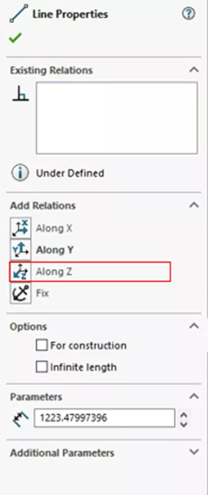
Figure 16: Adding Along Z Relation
Tangent
Going back to 2D sketches, Tangent Relations are used to make a combination of various entities tangent to each other. Entities that can be used are Arcs, Ellipse, Splines, and Lines. Two of these items can be selected, and once this relation is added, they will be tangent to one another.
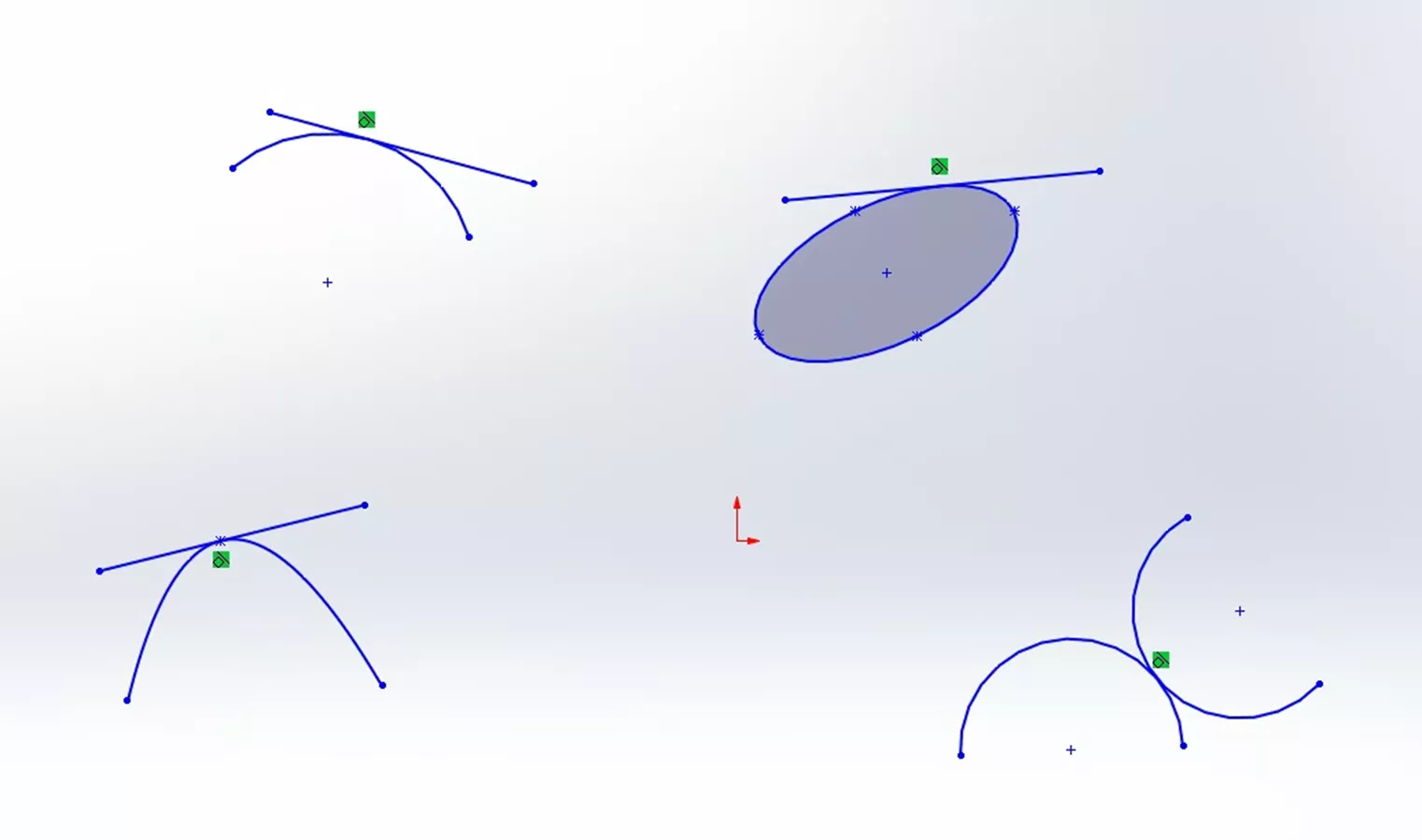
Figure 17: Tangent Relations
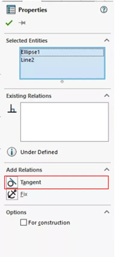
Figure 18: Add Tangent Relations
Concentric
Concentric Relations are relatively simple. This relation is created from either two arcs or an arc and a point. Concentric Relations force the arcs to share the same center point. Or, in the instance of an arc and a point, the point becomes the arc's center point.
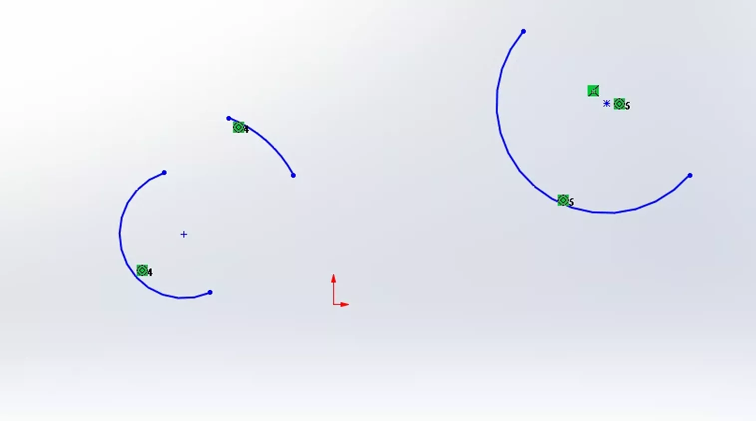
Figure 19: Concentric Relation
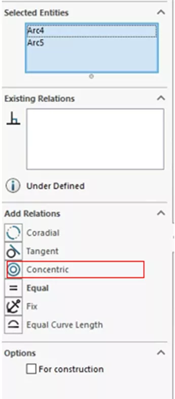
Figure 20: Add Concentric Relation
Midpoint
A Midpoint Relation is established from a line and some other point or endpoint. When two lines are used, one of the lines' endpoints will be selected as well as the second line.
Adding the Relation then sets the endpoint of the first line to be the same as the midpoint of the second line. When a point and a line are used the point becomes the same as the line’s midpoint.
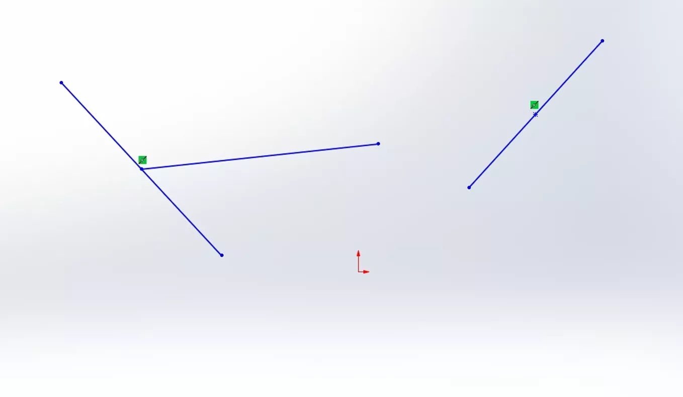
Figure 21: Midpoint Relation
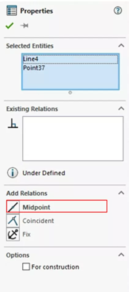
Figure 22: Add Midpoint Relation
Intersection
The Intersection Relation is a bit odd as it requires three entities to create: two lines and a point. When all three are selected, the point will be placed at the intersection of the two lines.
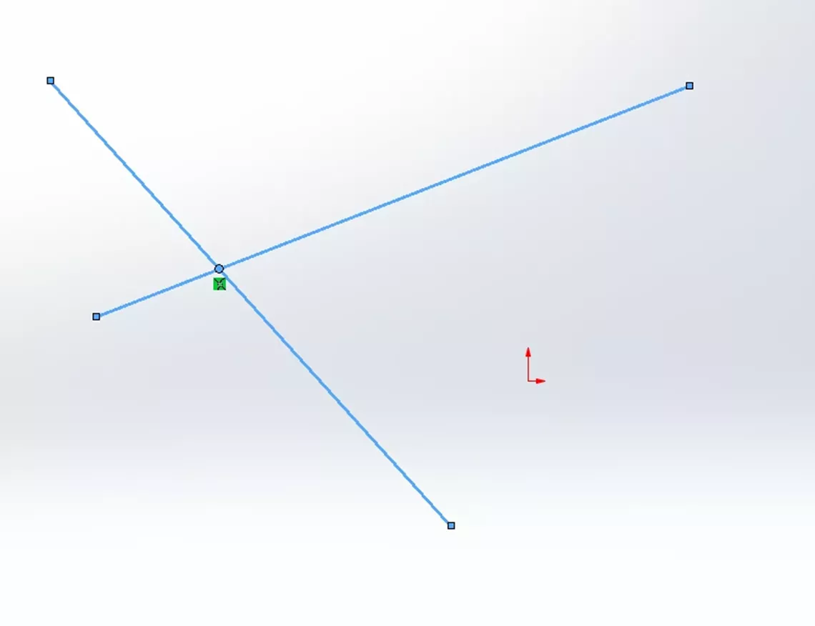
Figure 23: Intersection Relation
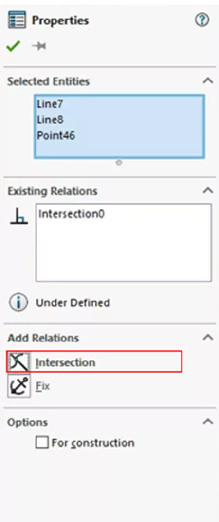
Figure 24: Add Intersection Relation
Coincident
One of the most quintessential relations in SOLIDWORKS. The Coincident Relation is made from a point (possibly an endpoint), and a line, arc, or ellipse. Selecting the point and one of the other entities allows the Coincident relation to be made, where the point will then lie on the other selected entity.
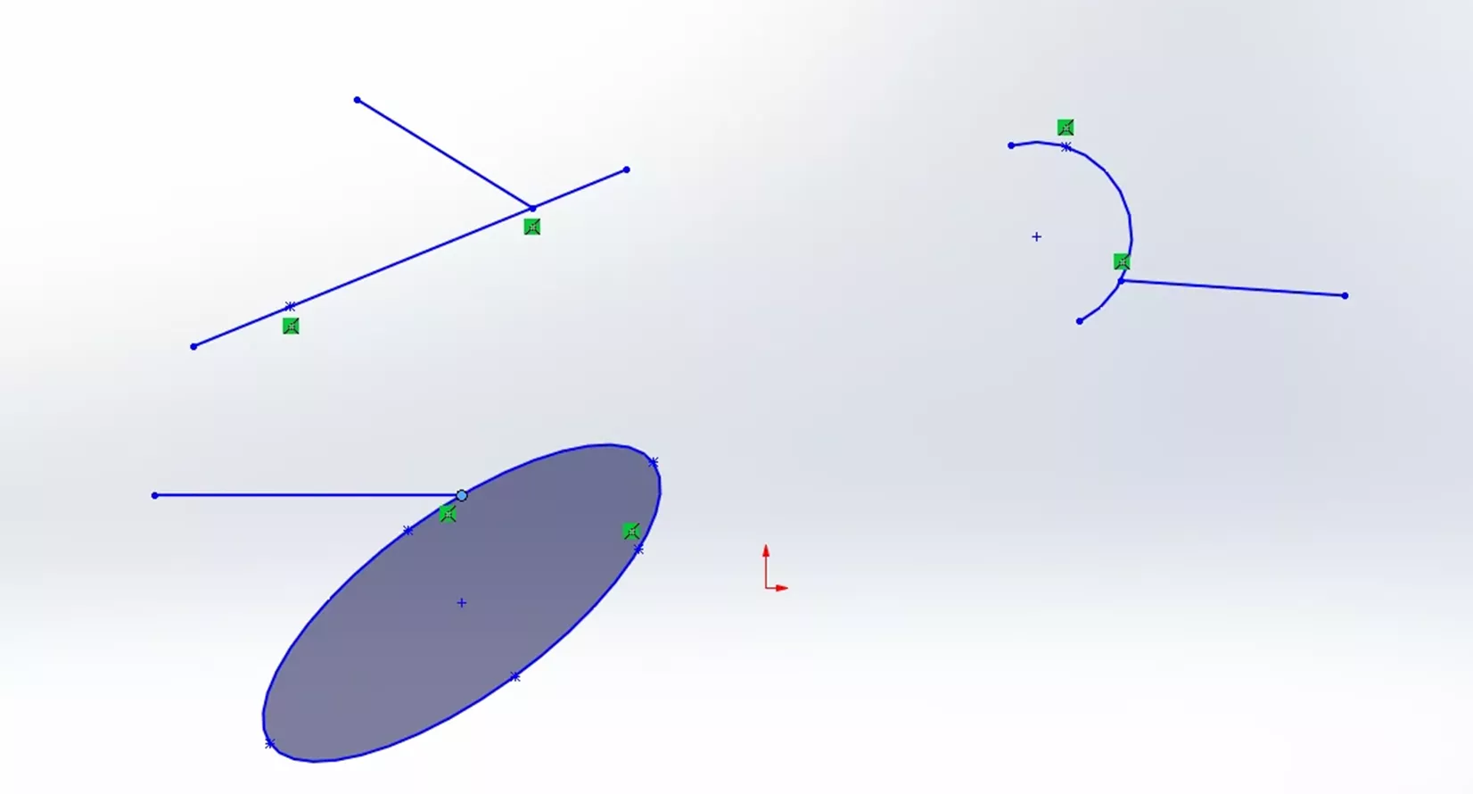
Figure 25: Coincident Relation
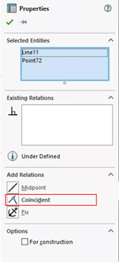
Figure 26: Add Coincident Relation
Equal
The Equal Relation is added to two or more lines or arcs. This makes lines have equal length while for arcs it makes the radii the same. This relation does have a little nuance that is not immediately apparent. When selecting the two entities, the first item selected is considered the base item and the second item will be set to match it. This is not the case if one entity is defined by a dimension. In that case, the item without a dimension will be set equal to the dimensioned entity regardless of selection order. This relation cannot be used if both items are defined by dimensions.
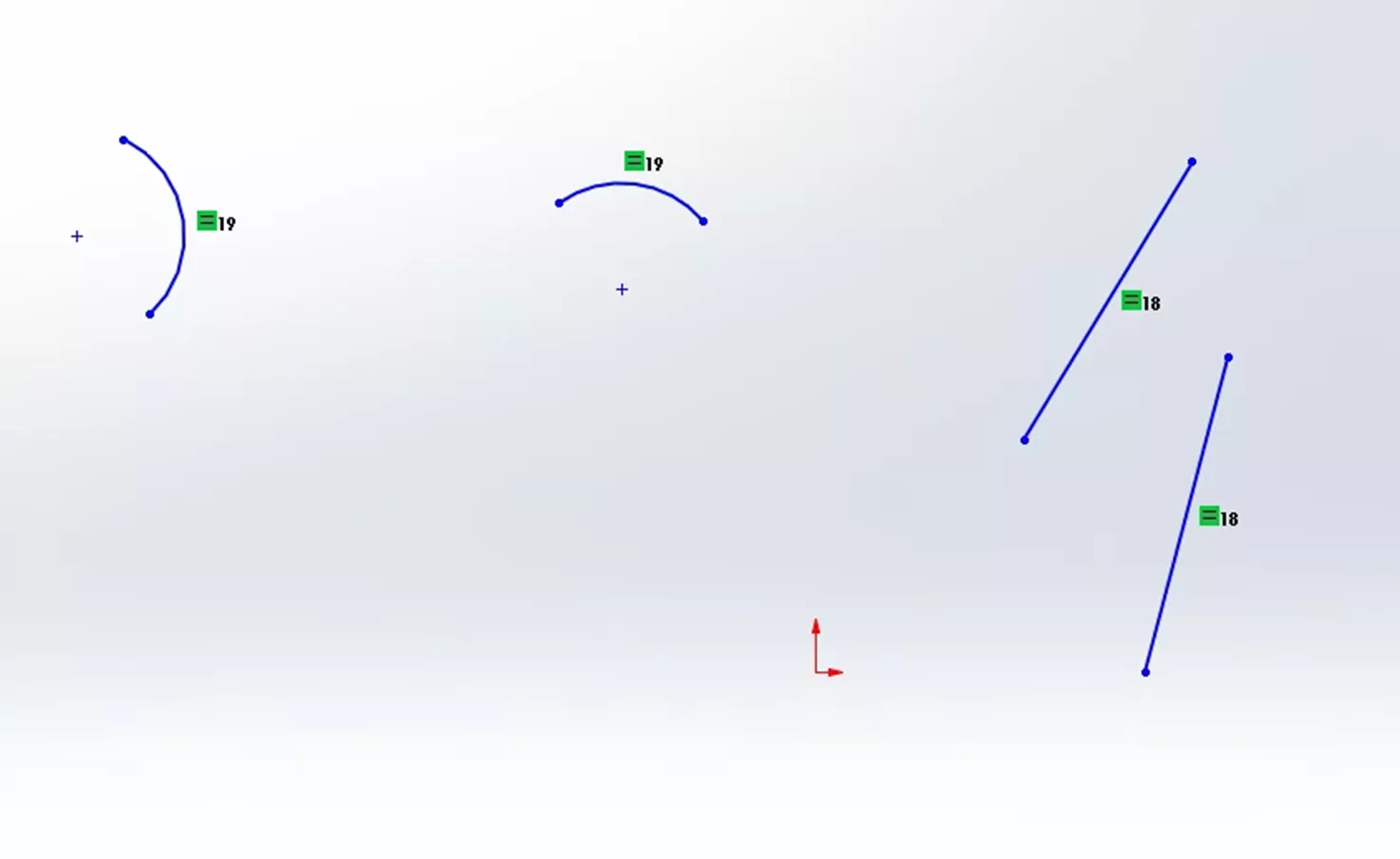
Figure 27: Equal Relation
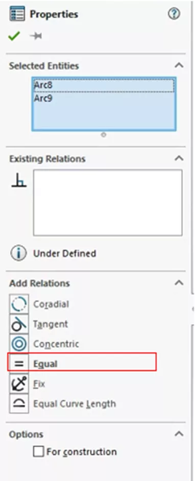
Figure 28: Add an Equal Relation
Equal Curvature
Equal Curvature is similar to the Equal Relation except it is created when two splines are selected. When this relation is used, the radius of curvature and the direction vector will be set to match between the two splines.
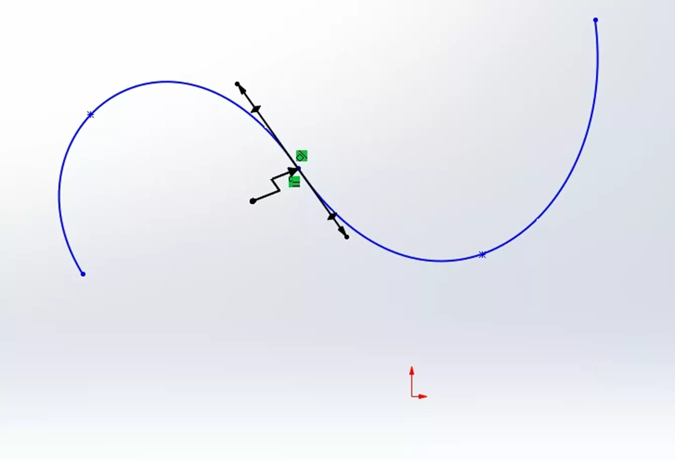
Figure 29: Equal Curvature Relation
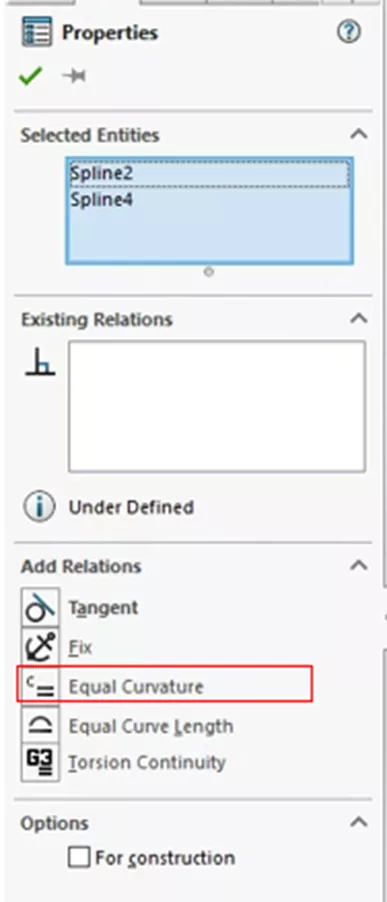
Figure 30: Add an Equal Curvature
Symmetric
Symmetric Relations add a new requirement: a center line. The required entities for this relation are two points, two lines, or two arcs and then a center line. When this relation is created, the two selected items will be equidistant from the centerline, and on a line perpendicular to the center line. Like the Equal Relation, the first entity selected sets the baseline and the second item will follow suit.
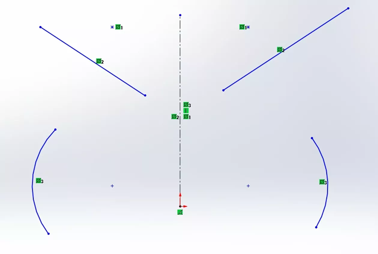
Figure 31: Symmetric Relation
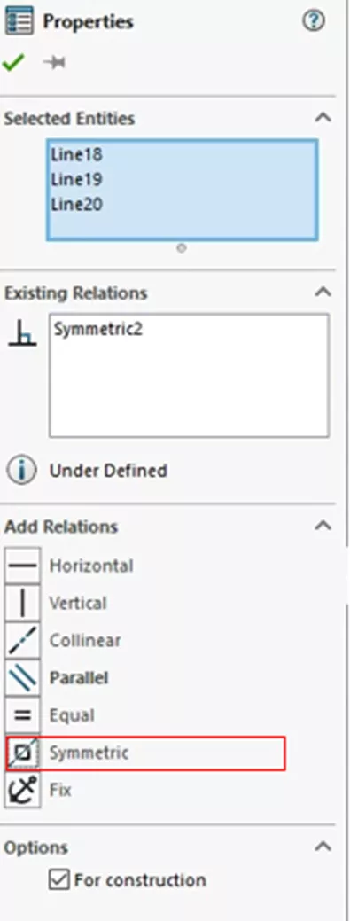
Figure 32: Add a Symmetric Relation
Fix
The Fix Relation is the simplest relation and can be applied to any entity you select. When this Fix Relation is added, the entitie's size and location are fixed. However, the endpoints of a fixed line are free to move along the infinite line that underlies it. Also, the endpoints of an arc or elliptical segment are free to move along the underlying full circle or ellipse. Be careful with Fix Relations as they drastically reduce your control over geometry by essentially pinning everything where it is if there are no dimensions involved to specifically control the locations.
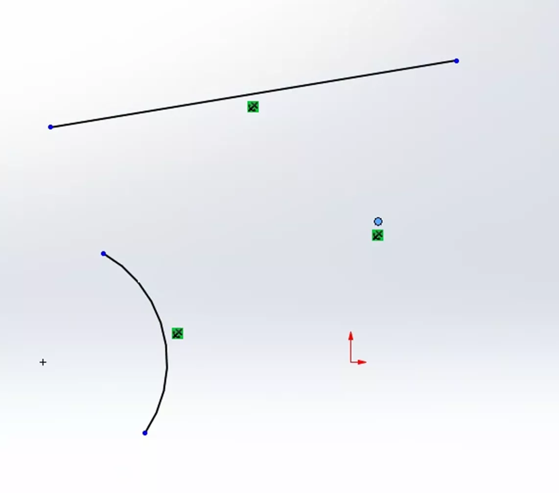
Figure 33: Fix Relation
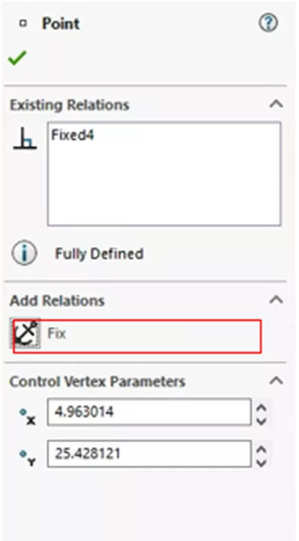
Figure 34: Add a Fix Relation
Fix Slot
The Fix Slot Relation has the same functionality as the Fix Relation but for Slot Sketch entities. When this relation is added to a Slot, the size and location are fixed.
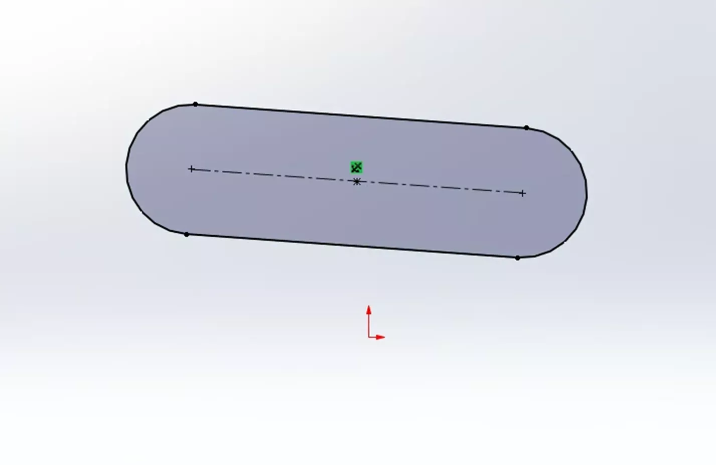
Figure 35: Fix Slot Relation
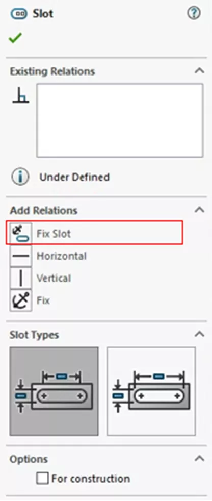
Figure 36: Add a Fix Slot Relation
Pierce
The Pierce Relation is a bit of a special case compared to other relations. This is due to it being tied to a specific function. While not fully exclusive to the Sweep function, this relation is used when making sweeps with guide curves. To create a Pierce Relation, you need a point and either an axis, edge, line, or spline. Once made, the Sketch point is coincident to where the chosen entities pierce the sketch plane.
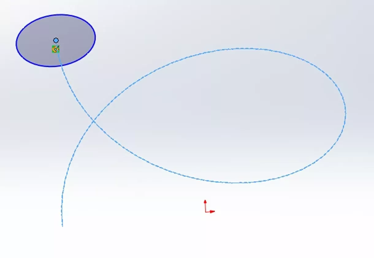
Figure 37: Pierce Relation
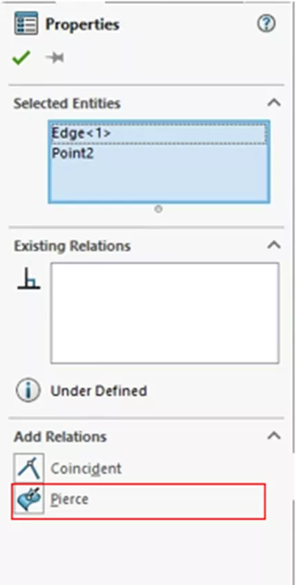
Figure 38: Add a Pierce Relation
Merge Points
The Merge Points Relation (or simply Merge Relation) is used when two points/endpoints need to, as the name suggests, merge together. This can be done by selecting both points and choosing the Merge option. Note: After this relation has been made, there is no green icon showing this relation; the extra point is simply removed.
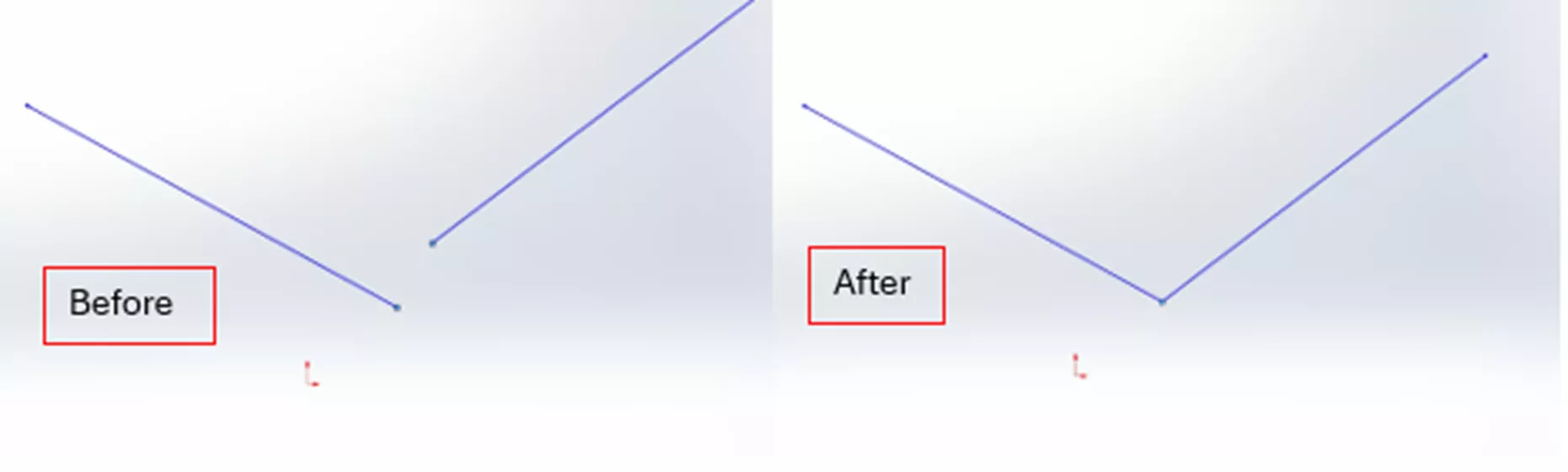
Figure 39: Merge Points Relation
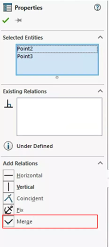
Figure 40: Add a Merge Points Relation
Doubled Distance
The Doubled Distance Relation is made in conjunction with the Smart Dimensioning tool. In fact, this relation isn’t shown as a relation but as a dimension. To create this relation, you will need a sketch entity and a center line.
To create a Doubled Distance Relation, turn on the smart dimension tool and select the sketch entity and the center line. Move your cursor to the other side of the center line. This should produce a dimension that is double the distance between the sketch entity and the center line.
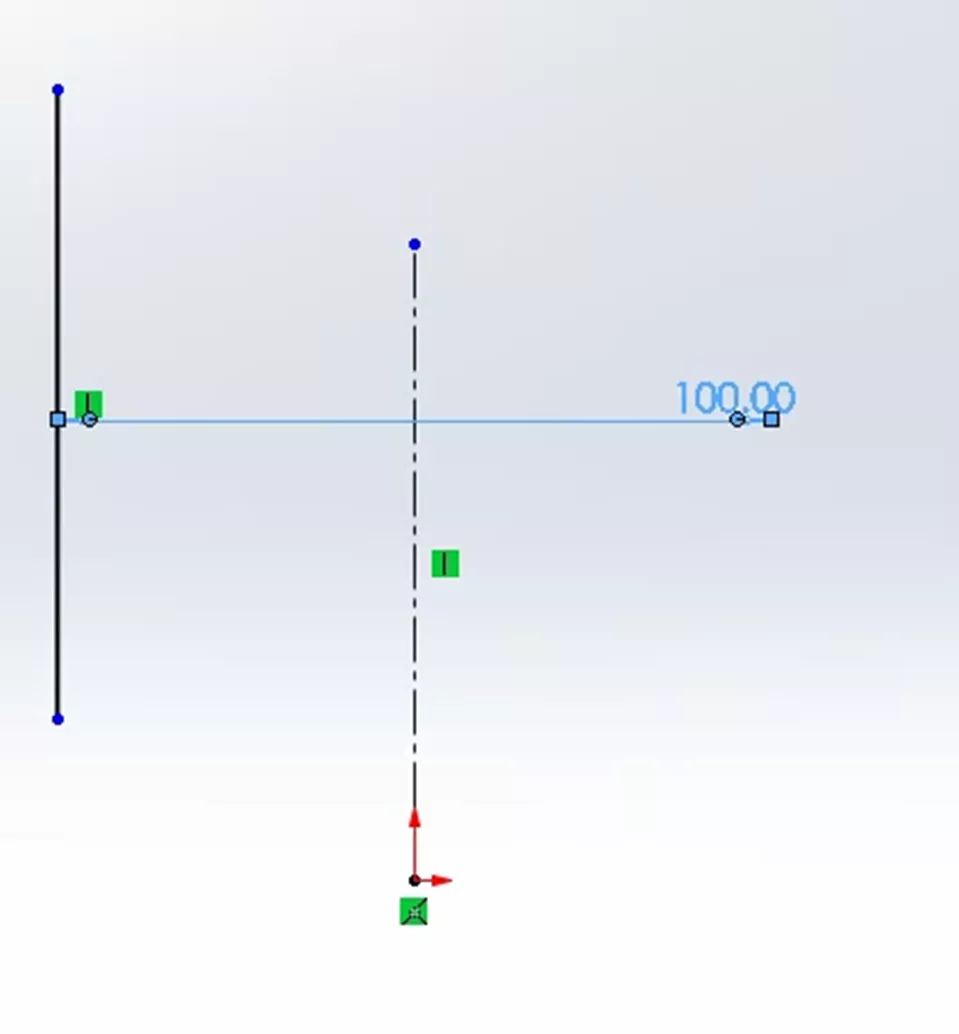
Figure 41: Double Distance Relation
Equal Slots
Much like Equal Relations, the Equal Slots Relation makes two or more Slots Equal. The same caveats apply here, where the first slot is selected unless a baseline slot or a dimensioned slot is selected.
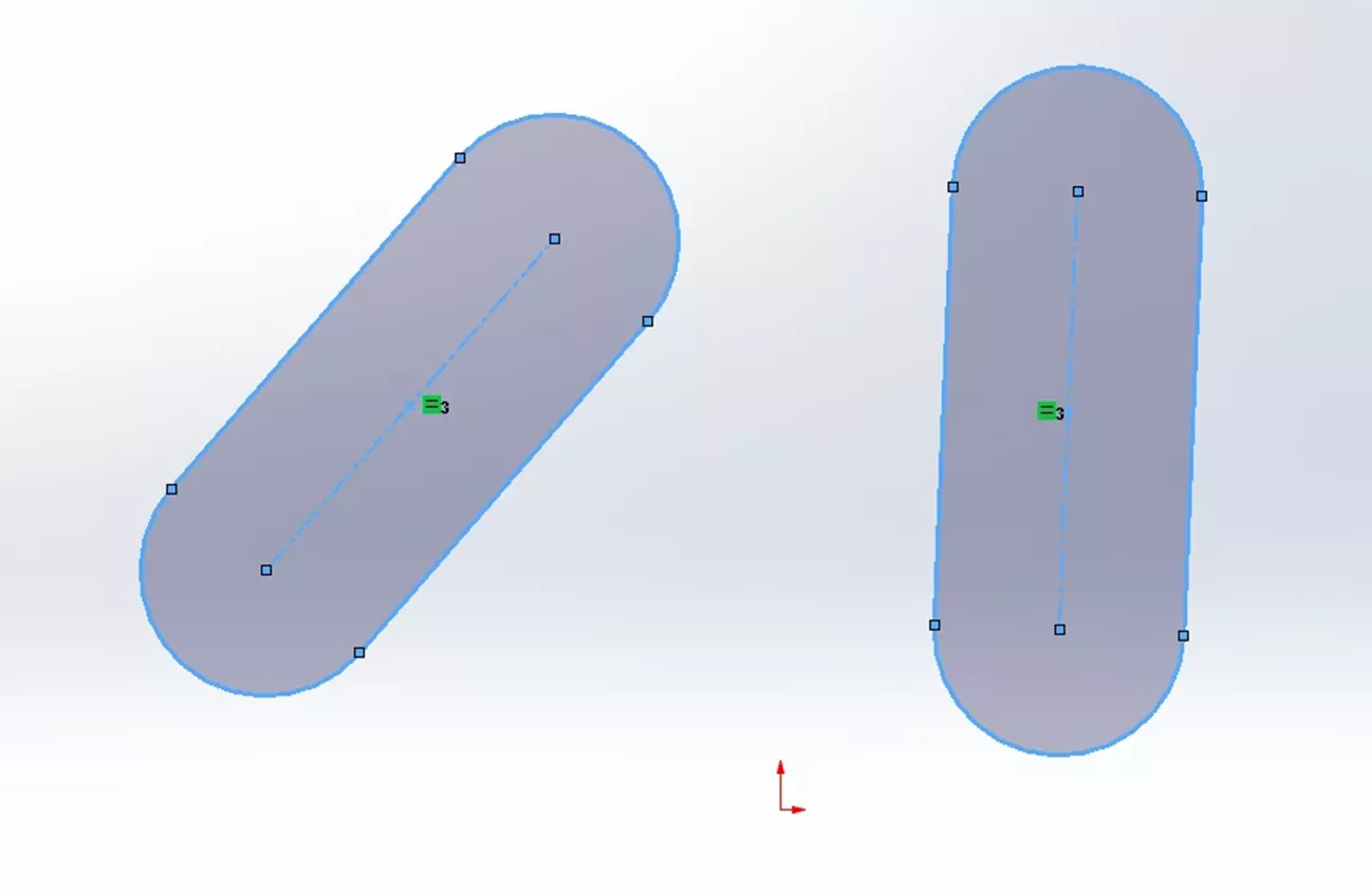
Figure 42: Equal Slots Relation
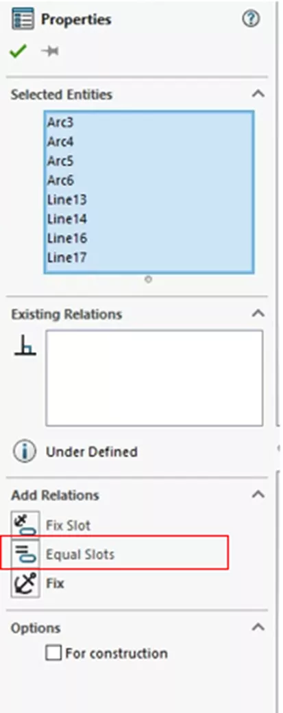
Figure 43: Add an Equal Slots Relation
On Edge
On Edge Relations are special in that they are not a relation you select or make yourself. They are relations that are created from using the Convert Entities tool. To make the relation, you need an existing solid body and a new sketch. From there, you can use the Convert Entities tool on one or more edges of the existing solid body. This will project the edge into your sketch as new geometry having the On Edge Relation.
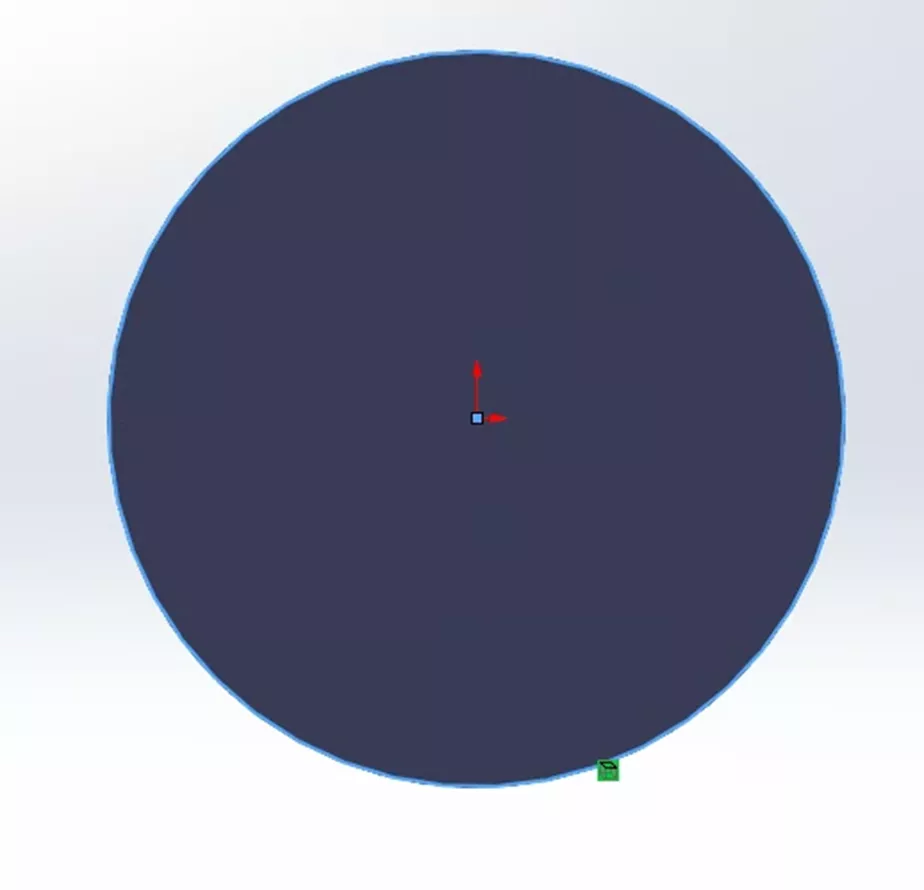
Figure 44: On Edge Relation
On Plane
The On Plane Relation is not immediately apparent as it is not something you add but something inherent in making 2D sketches. The On Plane Relation refers to any sketch entity that exists on a plane.
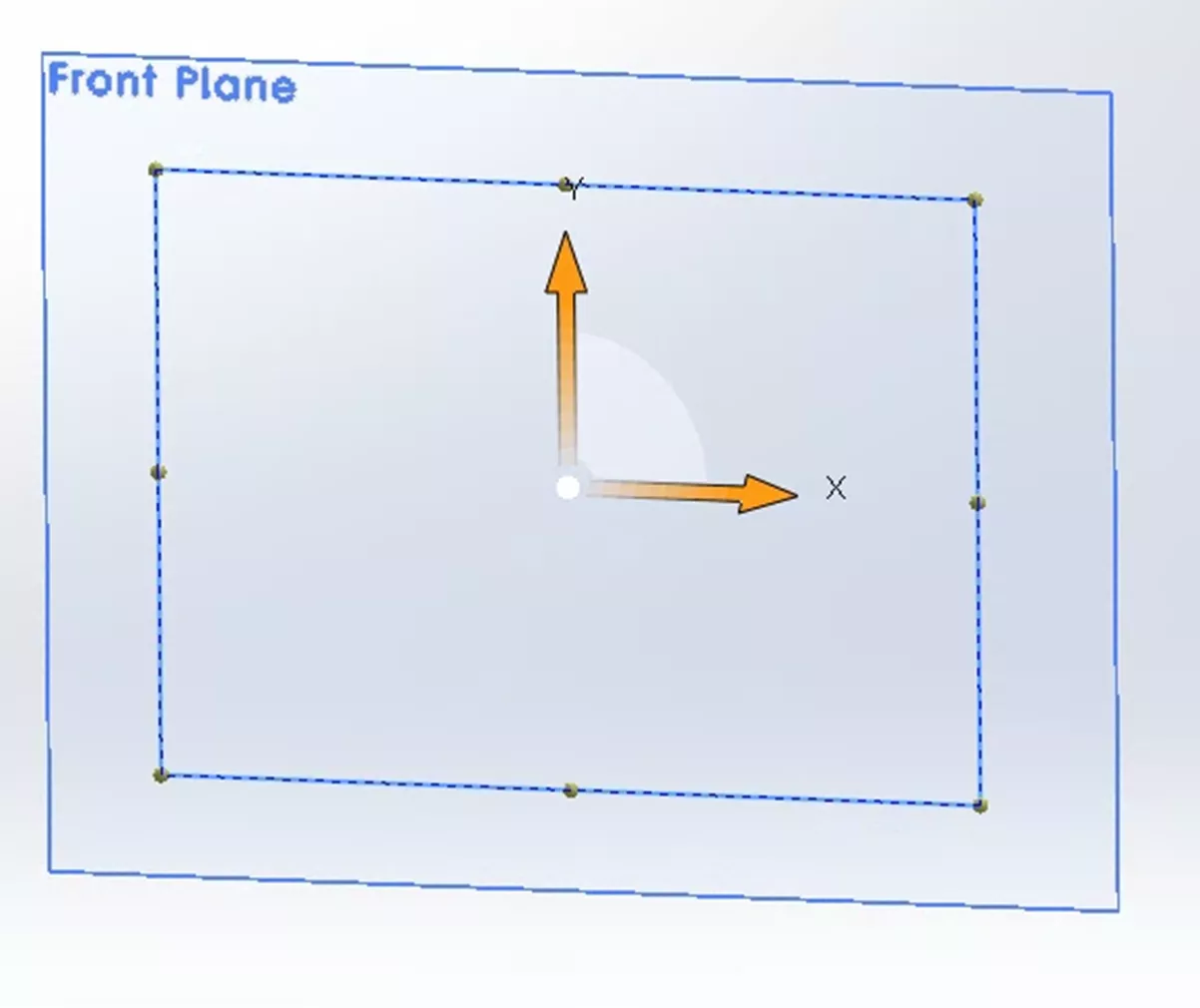
Figure 45: On Plane Relation
On Surface
An On Surface Relation requires an existing surface (it does not need to be planar) and a sketch entity created in a 3D sketch. Selecting the entity and the plane in any order allows you to apply this relation.
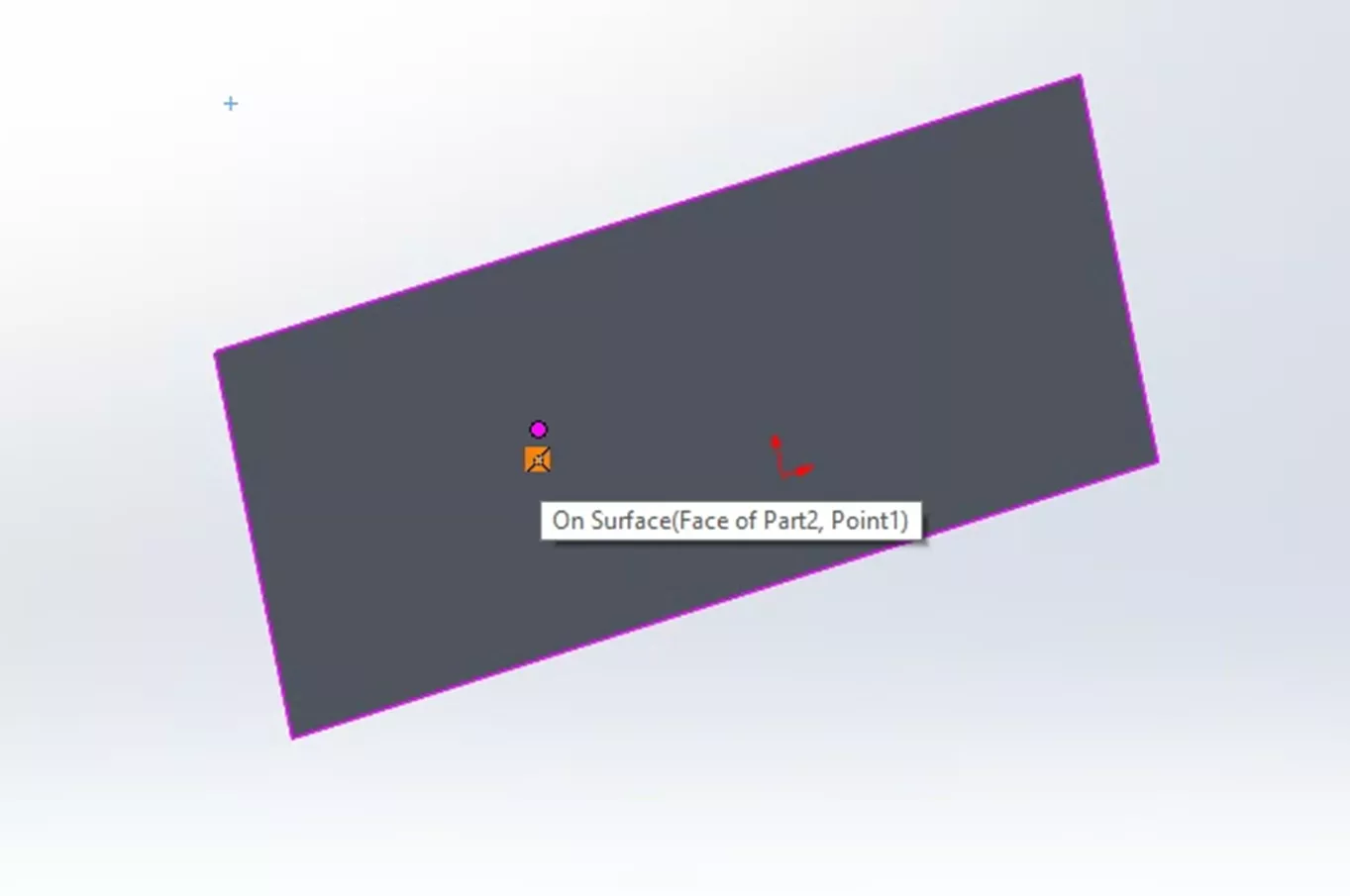
Figure 46: On Surface Relation
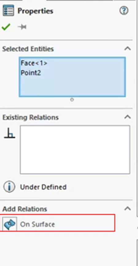
Figure 47: Add an On Surface Relation
Tangent to Face
The Tangent to Face Relation (also known as the Equal Curvature Relation) is created from a sketch entity and a face. When this relation is added by first Selecting the face and then the Sketch entity, the Sketch entity and face are made tangent to each other.
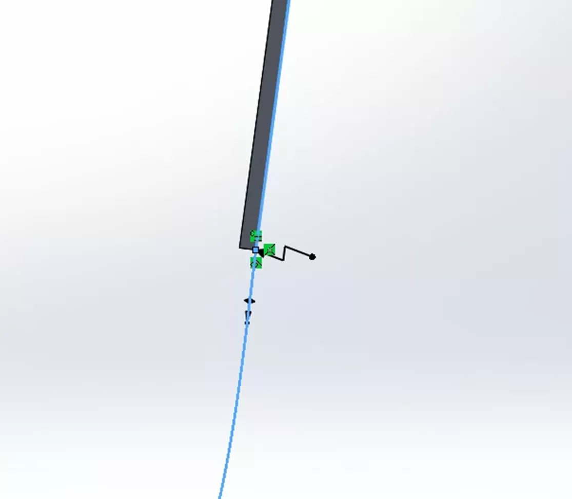
Figure 48: Tangent to Face/Equal Curvature Relation
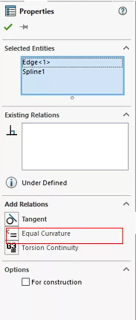
Figure 49: Add Tangent to Face/Equal Curvature Relation
Torsion Continuity
Torsion Continuity Relations are created from a spline and a spline, arc, conic or elliptical arc, or model edges that are linear, circular, conic, parabolic, elliptical, or spline-based.
This relation is used to obtain smooth continuity between the two entities at the shared endpoint. Torsion Continuity Relations are unique in that when created, Tangent and Equal Curvature Relations are created as well.
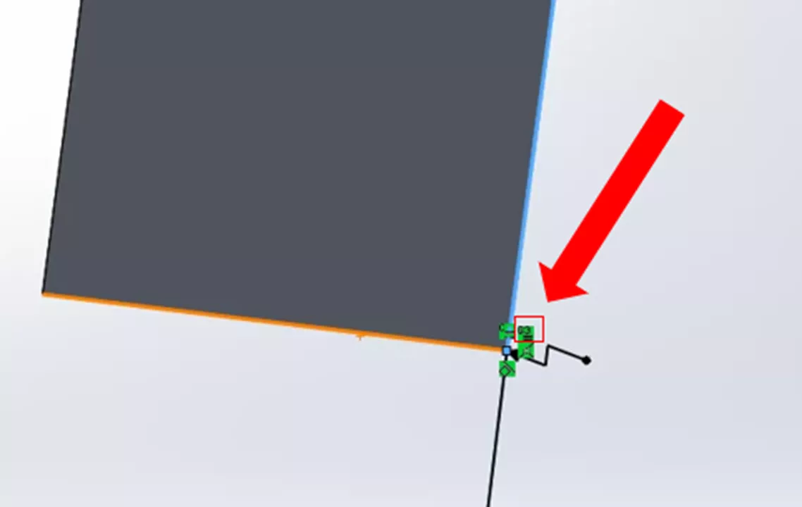
Figure 50: Torsion Continuity Relation
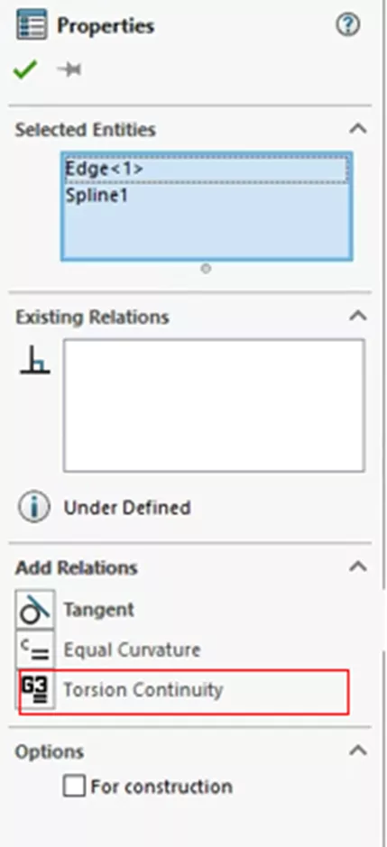
Figure 51: Add a Torsion Continuity Relation
SOLIDWORKS sketch relations and guaranteeing we pick the right ones are the foundation of parametric sketching. Getting it right at the beginning of the process will help you create robust models and features. To learn more about SOLIDWORKS, check out the tutorials listed below. Additionally, join the GoEngineer Community to participate in the conversation, create forum posts, and answer questions from other SOLIDWORKS users.

SOLIDWORKS CAD Cheat Sheet
SHORTCUTS ⋅ MOUSE GESTURES ⋅ HOT KEYS
Our SOLIDWORKS CAD Cheat Sheet, featuring over 90 tips and tricks, will help speed up your process.
More SOLIDWORKS Tutorials
SOLIDWORKS Animations Using Distance and Angle Mates
Importing a Vector Logo into SOLIDWORKS
Mastering SOLIDWORKS Model Display Properties
Changing SOLIDWORKS Temporary Graphics Colors
About Nathen Blas
Nathen Blas is a SOLIDWORKS Technical Support Engineer based out of our Headquarters in Salt Lake City, Utah. He earned his Bachelor’s degree in Mechanical Engineering at the University of Utah in 2018 and joined the GoEngineer family that same year.
Get our wide array of technical resources delivered right to your inbox.
Unsubscribe at any time.