How to Customize the SOLIDWORKS Hatch Pattern File
When using the Area Hatch/Fill tool in a SOLIDWORKS drawing, you can modify the scale and angle of the default pattern with options in the PropertyManager. If you constantly need to make changes to get the pattern you want, or if none of the out-of-the-box patterns fit with what you need, you can modify the SOLIDWORKS Hatch Pattern file to create a custom pattern. This article discusses how to create a custom pattern for use in the Area Hatch/Fill Drawing annotation too.
Where to Find the Hatch Pattern File
The Hatch Pattern file is a “.ptn” file that contains a list of patterns. The default location for your Hatch Pattern file is C:\Program Files\SOLIDWORKS Corp\SOLIDWORKS\lang\english. However, the location may vary depending on how you installed SOLIDWORKS. If you’re unsure, you can check where SOLIDWORKS is looking for the Hatch Pattern file on your computer by going to System Options > File Locations > Hatch Pattern File. The name of the file is sldwks.ptn.
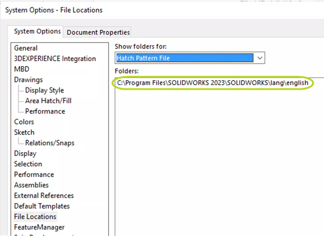
Figure 1: Hatch Pattern File location for SOLIDWORKS 2023 on a computer
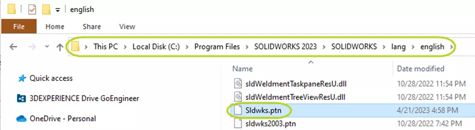
Figure 2: Hatch Pattern File location from Figure 1 open in Windows File Explorer
How to Read and Modify the SOLIDWORKS Hatch Pattern File
Open sldwrks.ptn in Notepad to edit it. We strongly recommend making a backup copy of sldwrks.ptn before making any changes.
The file begins with an explanation of how to read the table. Every pattern starts with “*:” followed by an identifying number. SOLIDWORKS has reserved numbers 001 through 500. So, if you’re making a new pattern, your ID needs to be 501 or a greater number.
After “*:”, the ID number, and another colon “:” is the name of the pattern followed by a comma, a space, and the description. The pattern definition is on the next lines.
Patterns are made up of line segments. Each line of the pattern data is a subpattern. To quote sldwrks.ptn, it “corresponds to a subpattern which consists of one bunch of parallel uniformly interspaced graphical lines with the same linear pattern on each of them (or all have no pattern i.e., to be drawn as solid lines)”.
This subpattern/line contains:
- The angle of the line
- The X and Y coordinates of where the line starts
- The X and Y spacing between the subpattern instances
Depending on the pattern you’re making, you might also include information about the length of and spacing between shorter colinear line segments.
Let’s look at the ANSI31 (Iron BrickStone) pattern as a simple example. Here’s the entry in the sldwrks.ptn file:
*:001:ANSI31 (Iron BrickStone), ANSI Iron, Brick, Stone masonry
45, 0,0, 0,.125
The first line specifies that the ID number is “001”, the name is “ANSI31 (Iron BrickStone)”, and the description is “ANSI Iron, Brick, Stone masonry”. The second line defines the first and only subpattern. The angle of the line is 45 degrees and starts at (0,0). Each of these solid, diagonal lines is (0,0.125) drawing units away from the previous one.
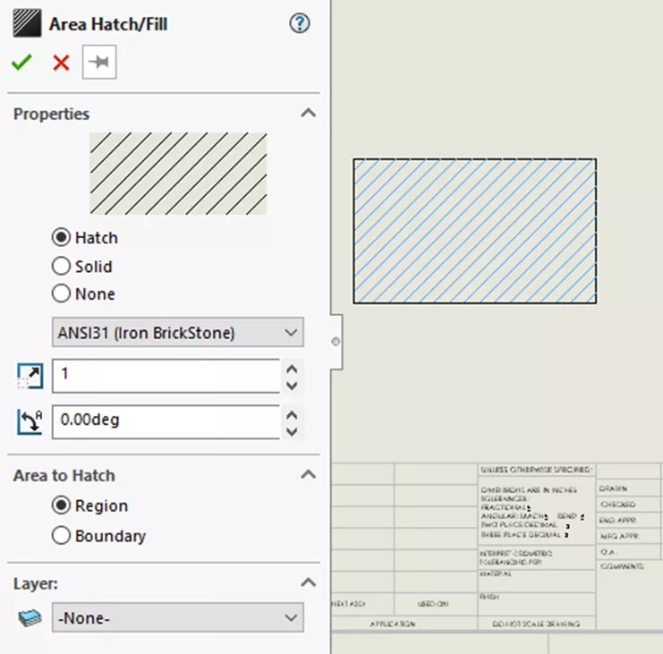
Figure 3: Area Hatch/Fill PropertyManager set to ANSI31 (Iron BrickStone) Pattern
DraftSight’s Help article about customizing Hatch Patterns has three additional, illustrative examples that are helpful when learning how to read patterns and create your own. Be sure to check that out if you want to create custom patterns yourself.
So, to make your own custom pattern, here are the steps you should follow:
- Find where sldwrks.ptn is stored on your computer by going to System Options > File Locations > Hatch Pattern File.
- Browse to that folder in a Windows File Explorer and open sldwrks.prn in Notepad.
- Scroll to the bottom of the document and, on a new line, create a header for your pattern.
- The syntax of your header will be: *:[ID Number]:[Pattern Name], [Pattern Description]. Note that there is no space between the second : and the Pattern Name but that there is a space between the comma after the Pattern Name and the Pattern Description.
- Enter your pattern definition.
The simplest way to create a custom pattern definition is to pick a similar, default one and modify it. It’s also possible to find additional Hatch Patterns used by other programs like DraftSight by searching the internet.
Conclusion
SOLIDWORKS makes it easy to use hatch patterns in your drawings. With a host of patterns stored away in the installation files, you can probably find what you need out of the box. However, if you need a custom pattern, it’s important that you know how to read the hatch pattern file so that you can make changes. But by following a simple convention, you can easily get the right pattern to fit your needs.
Want to learn more? Check out more SOLIDWORKS tips and tricks below. Additionally, join the GoEngineer Community to participate in the conversation, create forum posts, and answer questions from other SOLIDWORKS users.

SOLIDWORKS CAD Cheat Sheet
SHORTCUTS ⋅ MOUSE GESTURES ⋅ HOT KEYS
Our SOLIDWORKS CAD Cheat Sheet, featuring over 90 tips and tricks, will help speed up your process.
More SOLIDWORKS Tutorials
SOLIDWORKS Loft vs Boundary: Key Differences
How to Create Custom Cosmetic Threads in SOLIDWORKS
SOLIDWORKS Assembly Visualization Quick Tips
SOLIDWORKS Drawings - Utilizing $PRP for Linking Properties

About Lauren McGarry
Lauren McGarry is a Certified SOLIDWORKS Expert based out of San Diego, California. She earned her Bachelor of Science degree from Case Western Reserve University and has been with GoEngineer as a Technical Support Engineer since 2016.
Get our wide array of technical resources delivered right to your inbox.
Unsubscribe at any time.