How to Create Flex Features in SOLIDWORKS
The SOLIDWORKS Flex feature is a powerful tool for creating more flexible designs. With this feature, you can transform solids into fantastic shapes using the four types of flex options. This article will walk through the basics of the SOLIDWORKS Flex command and demonstrate how it will deform solids in an intuitive manner.
Where is the Flex Feature Located in SOLIDWORKS?
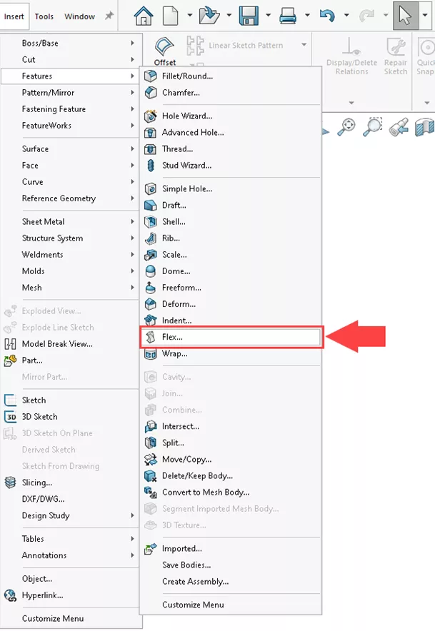
The Flex feature is found in the menu at Insert > Features > Flex...
There are four types of flex operations:
I will demonstrate each of these flex types and the result will be a solid that would challenge any experienced SOLIDWORKS modeler.
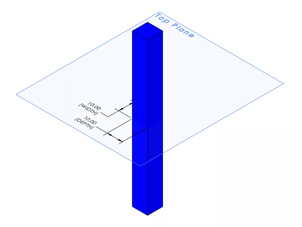
To begin, I have a square sketch on the Top Plane, then a midplane extrude to create a solid 10mm wide x 10mm deep x 100mm long.
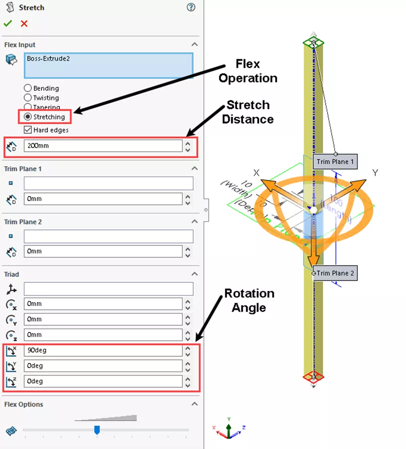
I will then begin to deform the solid using the Flex feature to add 200 mm to the length by stretching.
Stretching
Start the Flex feature and select Stretching, then add 200mm and set the axis as shown. SOLIDWORKS automatically places the trim Planes at the boundaries of the solid and leaves the triad at the center of the part.
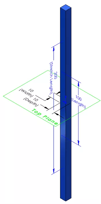
200mm will be added symmetrically to the length of the solid while keeping the Top Plane at the center of the solid. Click OK. The result will look like this:
Rename the feature “Stretch”.
Tapering
The next step is to apply a new Flex feature to Taper the top of the solid by 50%.
Select Tapering, then set the Taper Factor to .5 and select the origin for Trim Plane 2.
Set the rotation angle the same as previously, only the top half of the solid is affected.
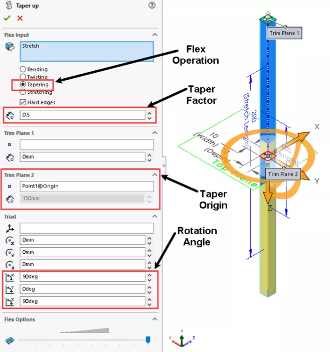
Click OK. The result will look like this:
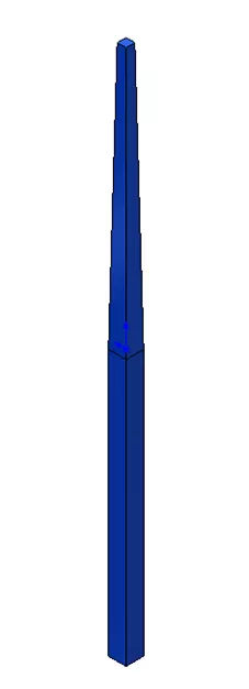
Rename the feature “Taper up”.
Now, apply another Flex feature to Taper the lower half of the solid.
This is accomplished with the same Tapering selection, input -.5 then select the origin to Trim Plane 1 with the previously set axes.
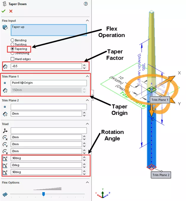
Click OK. The result will look like this:
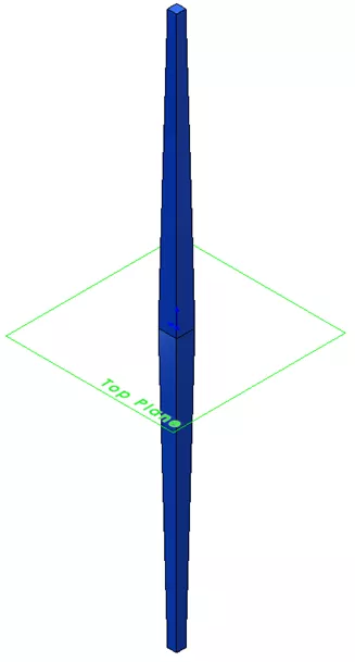
Rename the feature “Taper Down”.
Notice that the solid is still symmetric about the origin. This will be important as the shape of the solid is developed.
Then, add a new Flex feature to Bend the solid.
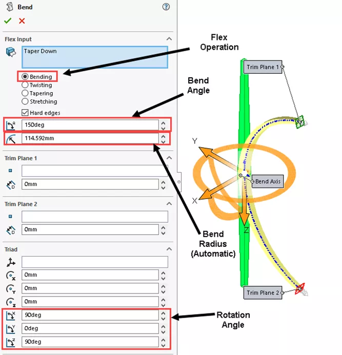
Bending
To do so, select Bending and apply a 180-degree bend with the previously set axes.
Note: The 114.592 radius setting is automatically driven by the angle.
Click OK. The result will look like this:
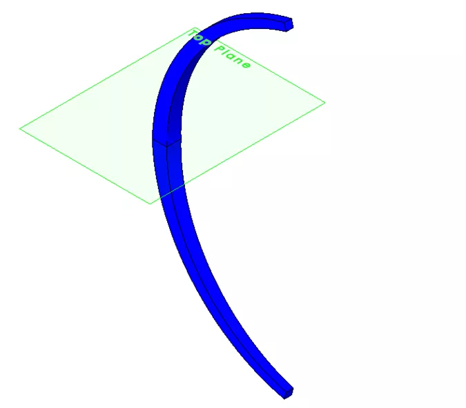
Rename the feature “Bend”.
Create a new Plane using the Right Plane and a vertex at the corner of the bend.
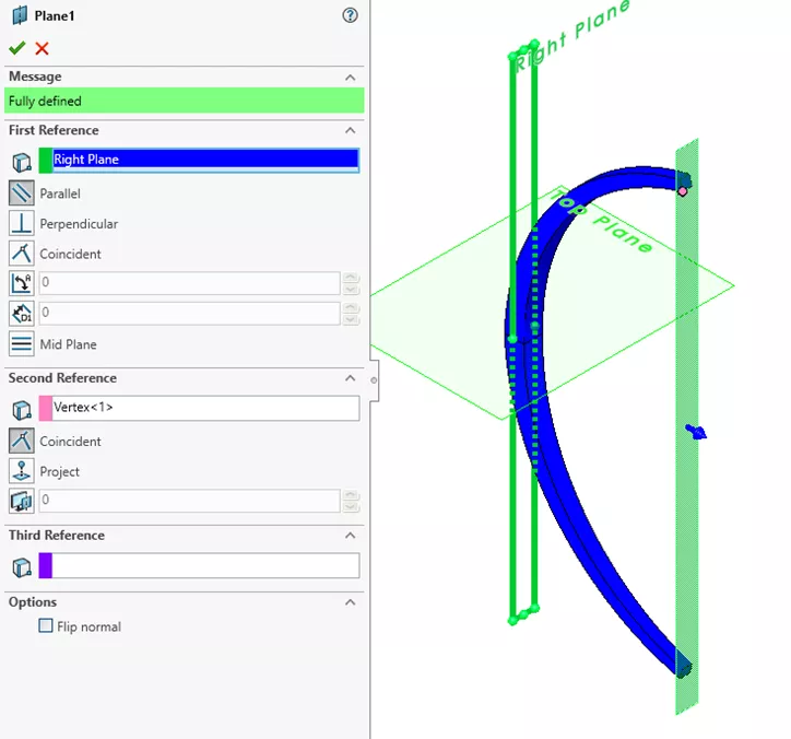
Rename the feature “Center Plane”.
This will be used to create a center of rotation for the circular pattern.
Now that the shape has been defined, a circular pattern will be created to apply the next Flex operation.
To facilitate the circular pattern, create an axis between the Center Plane and the Front Plane.
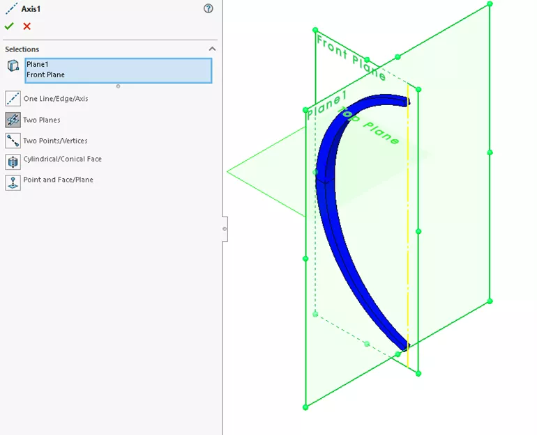
Rename the feature “Center Axis”.
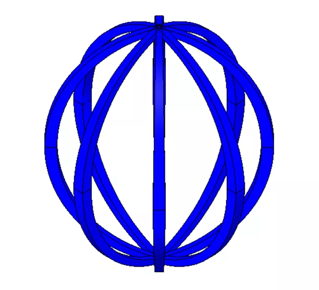
Use the Center Axis as the center of rotation to create a circular pattern of the bent body with 8 instances.
Add a coordinate system feature for the next Flex operation at X = 85.58 and the Center Axis in the Z direction.
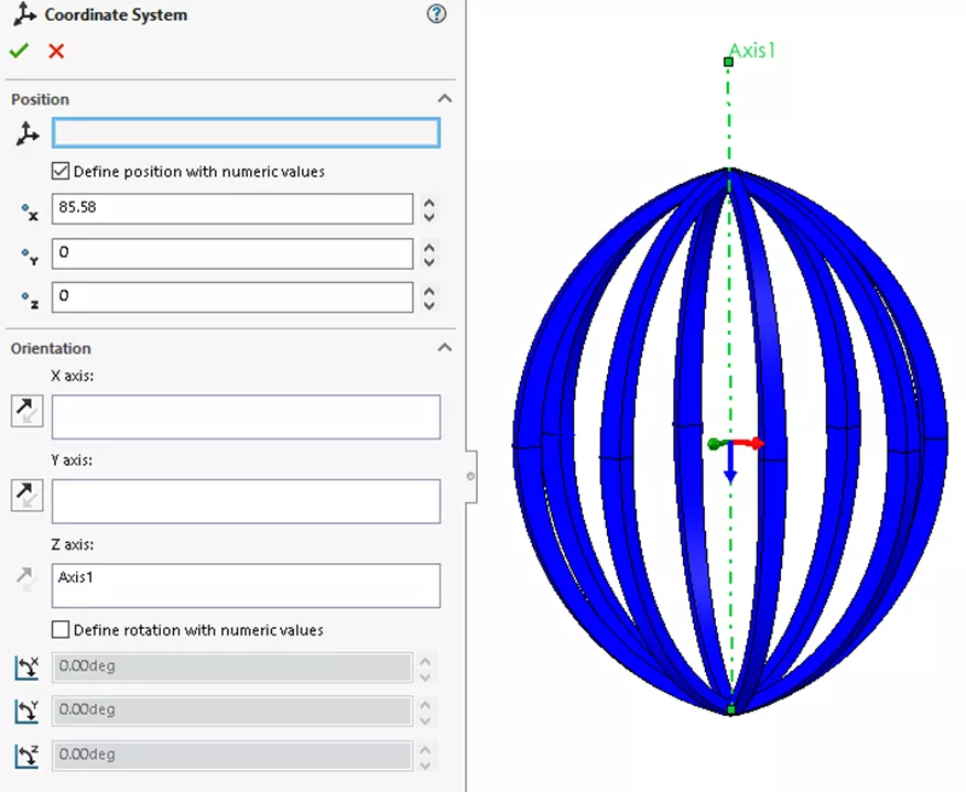
This will be used for the center of rotation for the last Flex feature
Twisting
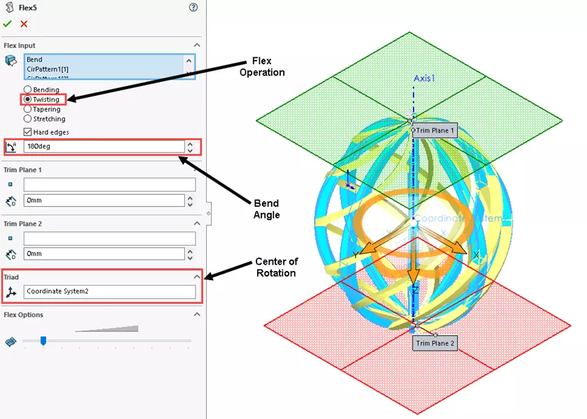
Insert a new Flex feature and apply a Twist operation to these solids. To do so, select the Flex operation for Twisting with a 180-degree angle.
The existing Coordinate system is used for the center of rotation.
Click OK. The result will look like this:
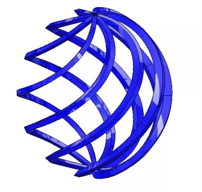
Rename the feature “Twist”.
To add more interest to this model, add a mirror feature of these bodies across the Top Plane. To eliminate some of the extra bodies, use the Merge Solids option.
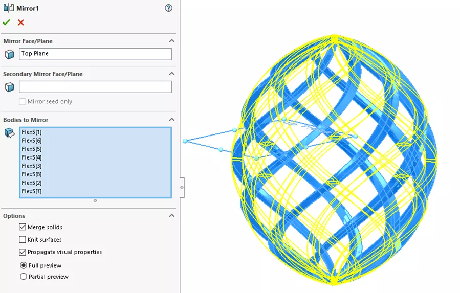
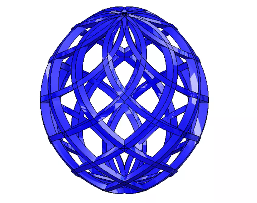
Click OK and the result will look like this:
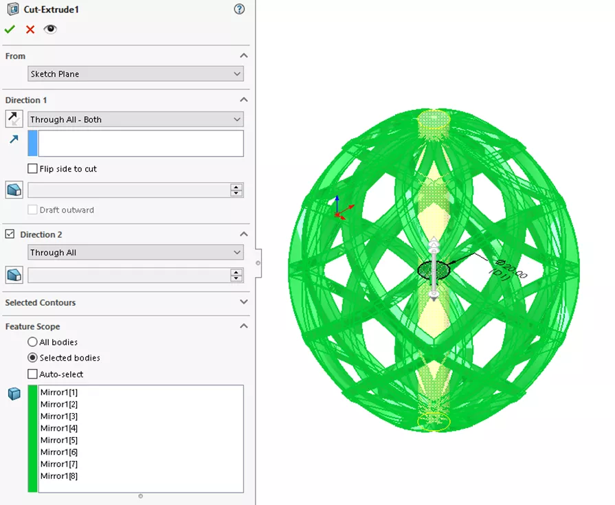
Create a sketch on the Top Plane and insert a 20mm diameter circle coincident to the Center Axis, then create a Cut-Extrude feature “Through all both”. This will facilitate the next feature.
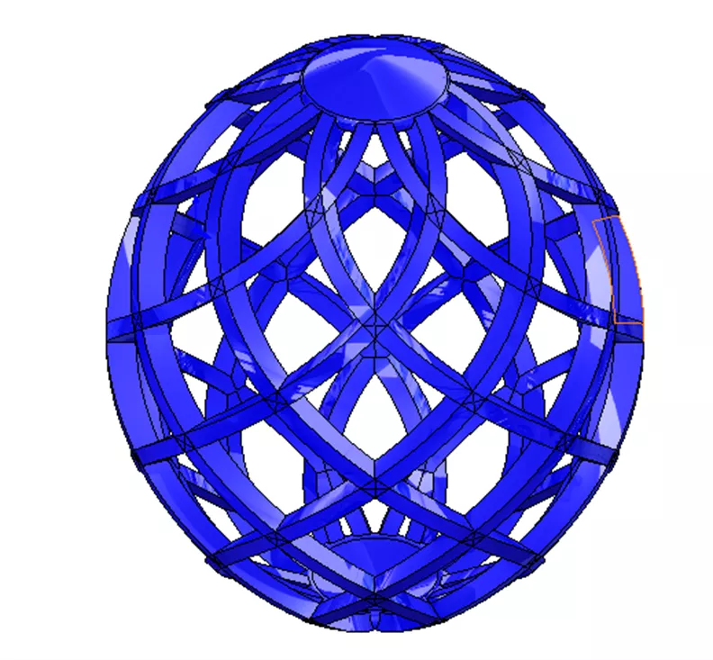
By adding a revolve feature at the top and then adding a Mirror feature across the Top Plane, all the solids will be merged, and the model is finished.
Finally, here is what the FeatureManager Design Tree looks like when finished.
I hope you have enjoyed this trip through the SOLIDWORKS Flex feature and will have an opportunity to use it with future designs.
Want to learn more? Check out our latest tips and tricks below. Additionally, join the GoEngineer Community to participate in the conversation, create forum posts, and answer questions from other SOLIDWORKS users.

SOLIDWORKS CAD Cheat Sheet
SHORTCUTS ⋅ MOUSE GESTURES ⋅ HOT KEYS
Our SOLIDWORKS CAD Cheat Sheet, featuring over 90 tips and tricks, will help speed up your process.
More SOLIDWORKS Tutorials
SOLIDWORKS Convert to Bodies Command Explained
SOLIDWORKS Limit Angle Mate Tutorial
SOLIDWORKS Drawings – Unable to Dimension Sheet Metal Bend Lines

About Dennis Barnes
Dennis Barnes is a CSWE, CSWI and a Sr. Applications Engineer based out of the Albuquerque, NM office since 2012. He has a BS in Computer Science from Chapman University and has been using SOLIDWORKS since 2005.
Get our wide array of technical resources delivered right to your inbox.
Unsubscribe at any time.