Misaligned Concentric Mates in SOLIDWORKS Explained
In SOLIDWORKS, a misaligned concentric mate is a way to link a pair of concentric mates that would otherwise over-constrain the assembly. By allowing some deviation, the mates can resolve without errors. For example, if you have components with a pair of holes, you can mate those components even when the holes are not the same distance apart.
Why Would I Need a Misaligned Mate?
Assemblies often use purchased components with fixed dimensions from the supplier that cannot be changed.
When minor differences in the hole location in one component and those in the other component exist, the misaligned mate can be very useful.
Mate parameters can be set so that one or the other of the concentric pairs is driving, forcing all the deviation on one side.
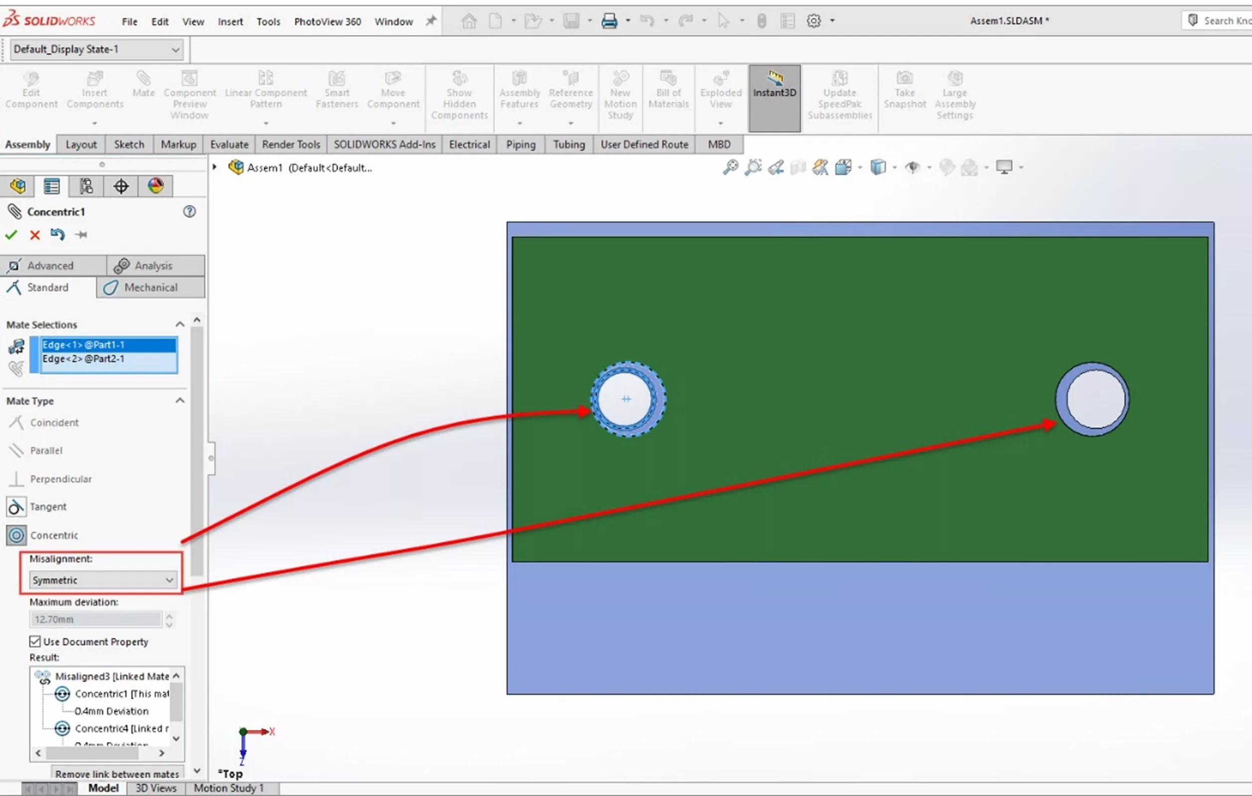
When the symmetric offset option is used, the deviation is split between the two pairs, effectively centering the component. Using this mate type can greatly simplify positioning and deviation determination. Previously, other mates and reference geometry would be required to get the part in the desired orientation.
Note: In some environments, using a misaligned mate may be problematic - so use with caution.
Applying Misaligned Concentric Mates
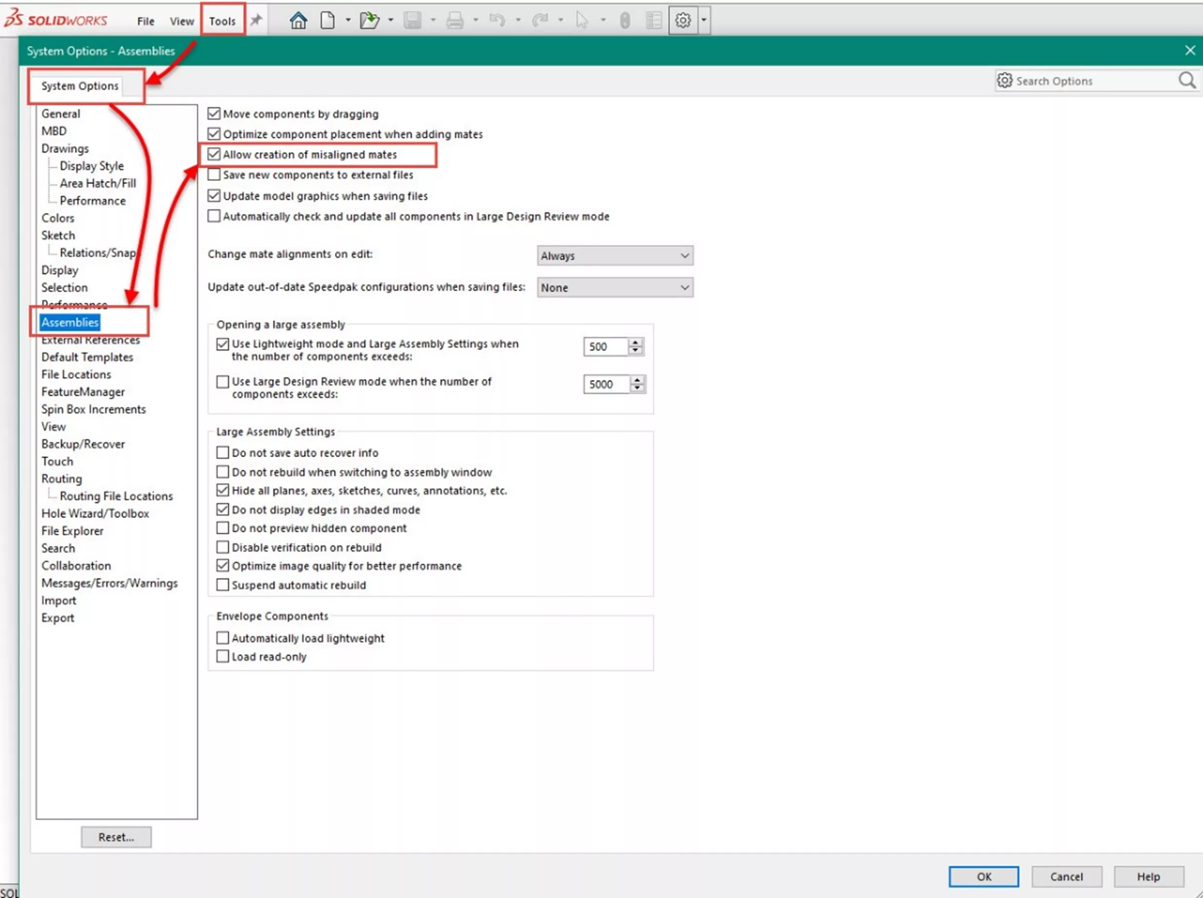
First, turn on the option to allow misaligned mate creation. Go to Tools > Options > System Options > Assemblies and select Allow creation of misaligned mates.
Misaligned Concentric Mates Example
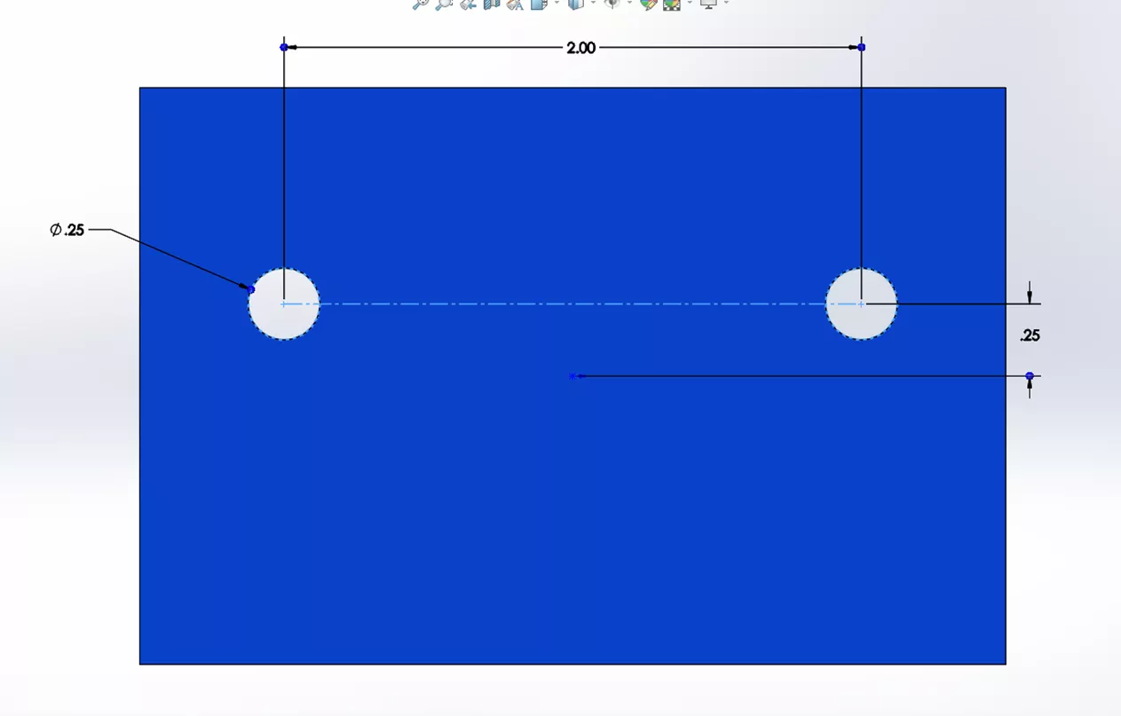
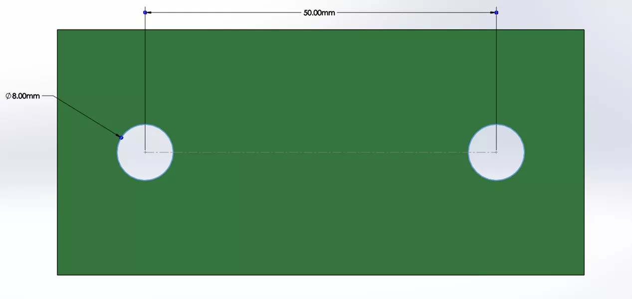
In this example, I have an assembly with one English component (blue) and a metric component (green). The hole centers are within usable limits, but using two concentric mates will not work. In my assembly, as with many, the goal is more about the positioning of the components.
I have mated one hole of each part with a concentric mate.
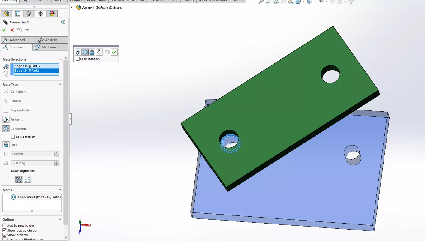
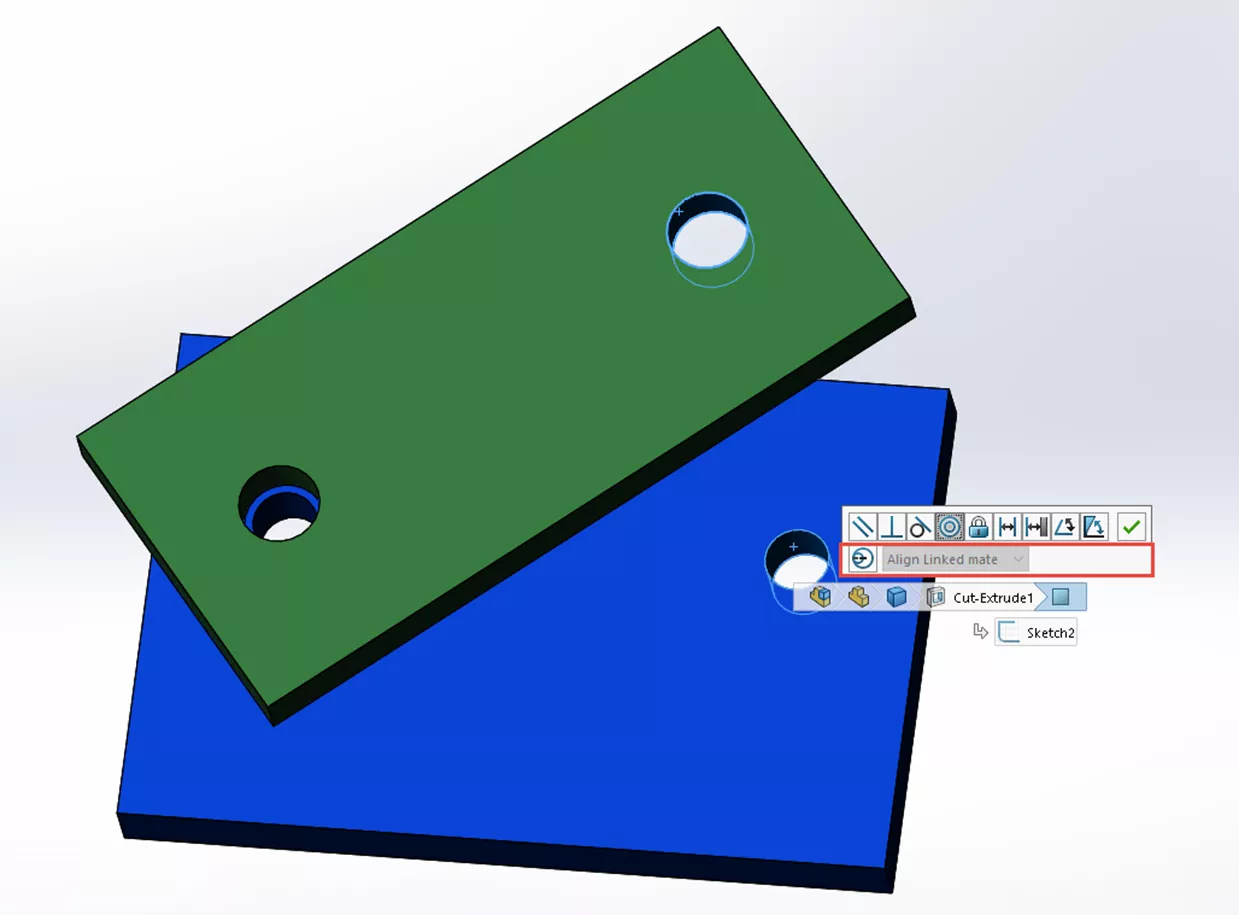
When a concentric mate is added to the other hole, a concentric mate conflict condition is detected and the misalignment option will appear with the concentric options.
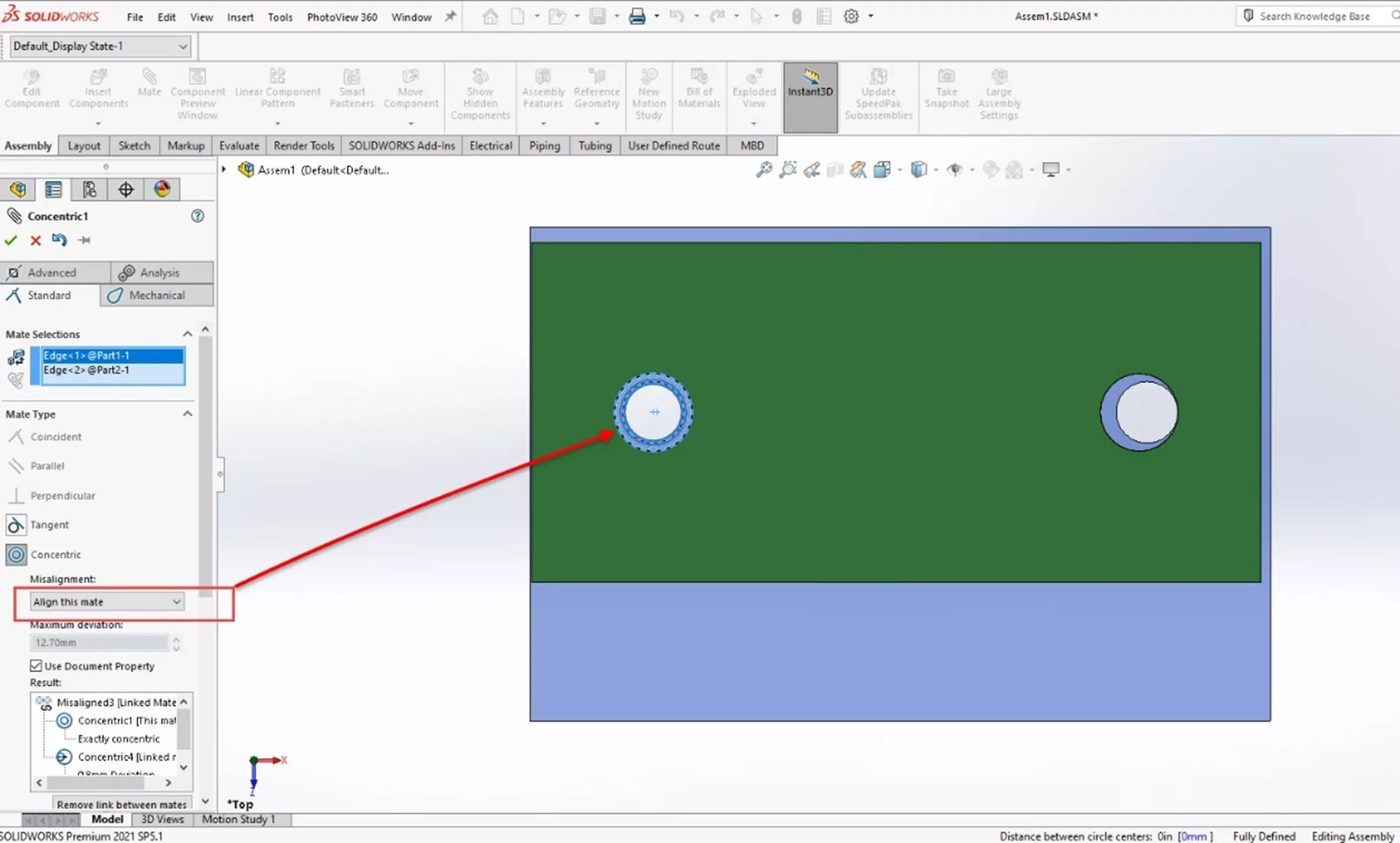
There are three settings for the orientation; these determine the location of the deviation.
- Align this Mate: Aligns to the primary concentric mate.
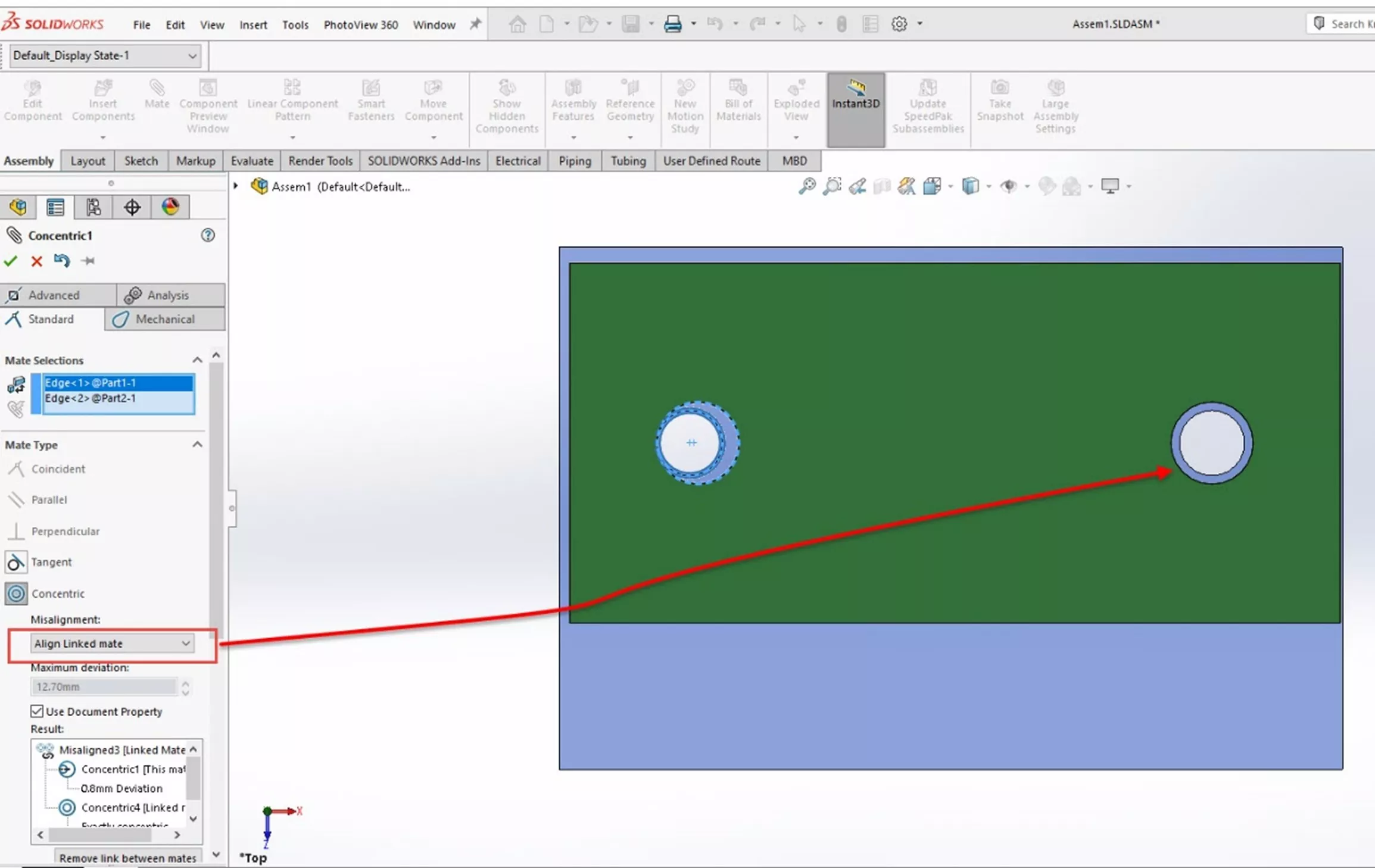
- Align Linked Mate: Aligns to the associated concentric mate.
- Symmetric: Aligns to divide the deviation between the two concentric mates.
By using these options for misaligned mates, you can easily position components that would otherwise cause mate conflicts or require other references to complete.
This feature should be used with some caution. Allowing misalignment can be useful but there are occasions where it may not be allowed or desirable.
I hope you found this article explaining misaligned concentric mates in SOLIDWORKS helpful. Check out more tips and tricks listed below. Additionally, join the GoEngineer Community to participate in the conversation, create forum posts, and answer questions from other SOLIDWORKS users.

SOLIDWORKS CAD Cheat Sheet
SHORTCUTS ⋅ MOUSE GESTURES ⋅ HOT KEYS
Our SOLIDWORKS CAD Cheat Sheet, featuring over 90 tips and tricks, will help speed up your process.
More SOLIDWORKS Mates Tutorials
Introduction to SOLIDWORKS Mates: Standard, Advanced, & Mechanical
Why SOLIDWORKS Mates Can Cause Slow Assemblies
Get our wide array of technical resources delivered right to your inbox.
Unsubscribe at any time.