SOLIDWORKS Simulation Degrees of Freedom and Fixtures
Each node in a model meshed for a Finite Element Analysis (FEA) study has six degrees of freedom or DOF. Three are translational and three are rotational. In order to stabilize the model, the nodes’ DOF must be constrained. Note: This SOLIDWORKS Simulation article is a companion to our SOLIDWORKS Simulation Tutorial - Fixtures Better Practices video.
6 Degrees of Freedom
In any FEA, the model is discretized into segments called elements. This is necessary in order to run stress equations throughout a part. In SOLIDWORKS, these elements are tetrahedrons. The points where tetrahedrons connect are called nodes.
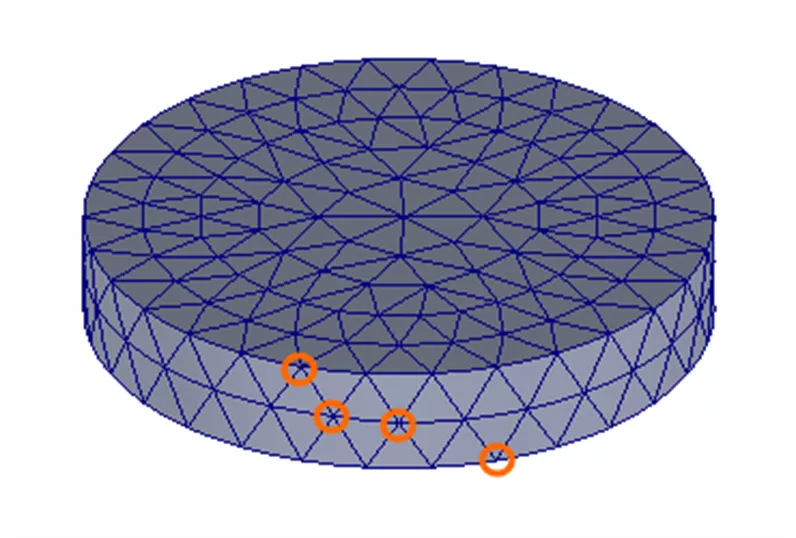
Figure 1: Meshed cylinder with examples of nodes circled
Each node has six Degrees of Freedom, (6DOF): three translational and three rotational. After a model has been meshed and broken up into tetrahedrons, its nodes are what need to be constrained.
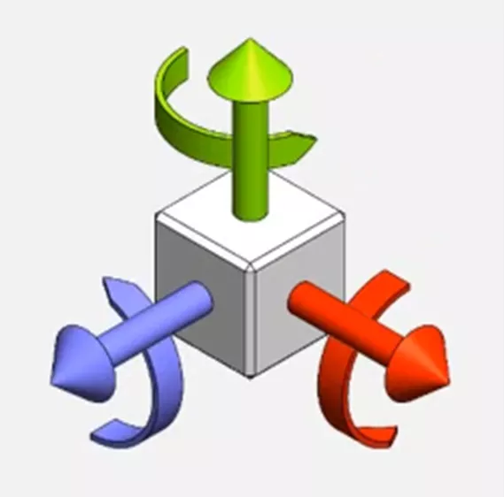
Figure 2: Degrees of Freedom
In some more involved simulation software programs like Abaqus, it's possible to select individual nodes and restrict their 6DOF. In SOLIDWORKS Simulation, we instead apply fixtures to model geometry like faces, edges, and vertices. This essentially selects all nodes on the chosen geometry and restricts their translation and/or rotation.
Standard Fixtures
There are three standard fixtures: Fixed, Roller/Slider, and Fixed Hinge.
- Fixed removes all 6DOF for the selected faces, edges, and vertices.
- Roller/Slider only allows degrees of freedom translationally in directions sitting on the plane of the selected face. The face's other four degrees of freedom are locked.
- Fixed Hinge removes the three translational degrees of freedom and allows only one rotational degree of freedom about the selected cylindrical face.
Figure 3: Standard Fixture icons and associated DOF. Top to bottom: Fixed, Roller/Slider, Fixed Hinge
Advanced Fixtures
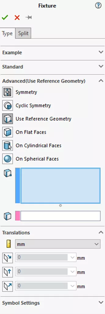
The six Advanced Fixtures offer more granular control: Symmetry, Cyclic Symmetry, Reference Geometry, On Flat Faces, On Cylindrical Faces, and On Spherical Faces.
![]()
Figure 4: Advanced Fixture icons and associated DOF. Clockwise from top left: Symmetry, Reference Geometry, On Cylindrical Faces, On Spherical Faces, On Flat Faces, Cyclic Symmetry
- On Flat Faces is similar to Roller/Slider in that it controls the translational degrees of freedom for a selected planar face. The translations that can be restricted - or not - are normal to the planar face and the two in-plane directions. To restrict a DOF in any of the Advanced Fixtures, you must select it under the Translations section of the PropertyManager. Leaving the value at 0 prevents the face from moving in this direction.
- On Cylindrical Face allows you to independently control rotational degrees of freedom. These are Radial, Circumferential, and Axial.
- On Spherical Faces is a combination of radial and longitudinal & latitudinal rotational degrees of freedom.
- Symmetry and Cyclic Symmetry are special because they tell the solver that there is more mass on the other side. Otherwise, they control the same degrees of freedom as the On Flat Faces and On Cylindrical Faces fixtures respectively.
- Reference Geometry is the most powerful and nuanced Advanced Fixture. It alone can recreate all other fixtures listed above. You can pick vertices, edges, and faces. Depending on the reference geometry you select, you can control either translational or rotational degrees of freedom. If you select a plane or flat face, you can control translational DOF. An axis or cylindrical face will give you options for rotational DOF. Finally, if you select an edge, you can control displacement along that edge.
Application
Different combinations of fixtures can produce the same results if they're constraining the same nodes' DOFs in the same ways. After running your study, if your results don't look right, you may need to go back and add or edit fixtures.
For example, if you apply a Fixed fixture to a face that should be able to slide - that is, that should not have restricted translational DOFs - then this can add non-real stiffness to your model.
Too few fixtures can result in your model translating or rotating in a way you don't want. This can throw off your Displacement results. Applying a Reference Geometry fixture to one or more vertices is one way to stabilize the model.
I hope you found this article explaining SOLIDWORKS Simulation degrees of freedom and fixutres helpful. Check out more tutorials below. Additionally, join the GoEngineer Community to participate in the conversation, create forum posts, and answer questions from other SOLIDWORKS users.
Ready to take your Simulation skills to the next level? Enroll in an official SOLIDWORKS Simulation training course. These courses range from Simulation Essentials to Advanced topics. Both in-person and online options are available.
More SOLIDWORKS Simulation Tutorials
SOLIDWORKS Simulation Fixture Preview Icons Explained
SOLIDWORKS Simulation Iso Clipping Tool: PropertyManager Walkthrough
SOLIDWORKS Simulation CAD Conditioning with Shell Elements
Why Use Hex Elements in Your FEA?

About Lauren McGarry
Lauren McGarry is a Certified SOLIDWORKS Expert based out of San Diego, California. She earned her Bachelor of Science degree from Case Western Reserve University and has been with GoEngineer as a Technical Support Engineer since 2016.
Get our wide array of technical resources delivered right to your inbox.
Unsubscribe at any time.