SOLIDWORKS Simulation Fixture Preview Icons Explained
In this guide, we cover SOLIDWORKS Simulation fixture preview icons and what they represent. While building SOLIDWORKS Simulation studies, it is important to create the right fixtures so that the results are accurate. By understanding the fixture preview icons and how they relate to the different types of fixtures, it becomes much easier to quickly create the correct fixtures.
How to Apply Fixtures
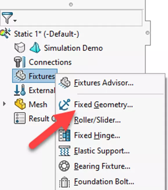
To apply a fixture in SOLIDWORKS Simulation, right-click Fixtures in the FeatureManager Design Tree and choose a restraint. There are many ways to apply fixtures, but for this example, let's choose Fixed Geometry.
Fixture Preview
In the Fixture PropertyManager, select Fixed Geometry. Once Fixed Geometry is selected, the PropertyManager will display a preview of what will happen to the model using this fixture.
The preview shows that the face, highlighted in green, is fixed in space and cannot move. The preview also animates the deformation of the rest of the model after a force is applied.
![]()
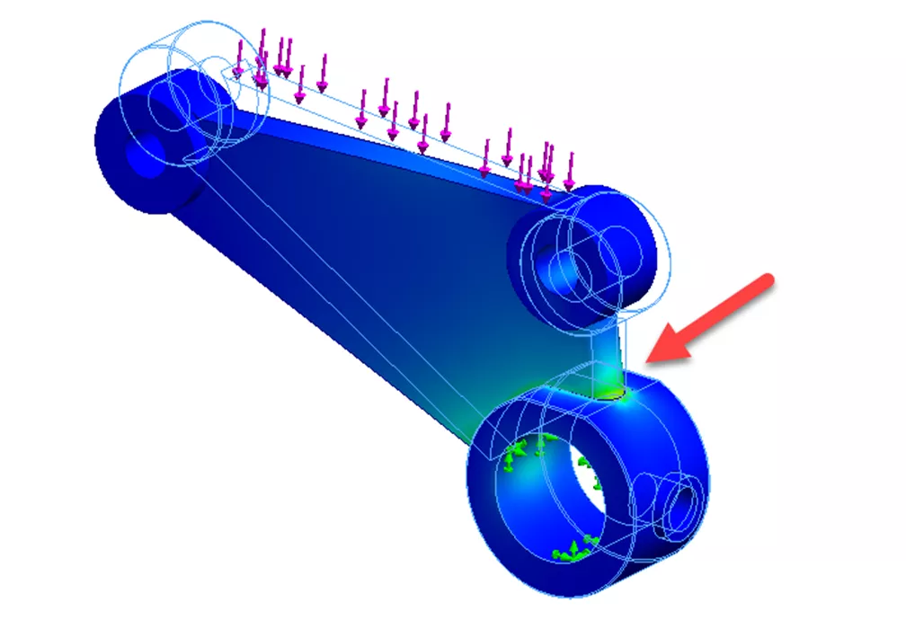
Without this fixed geometry, the force would be applied evenly, and we would not see any strain or displacement. In this example, we have a model where the inner surface of a hole is selected for the fixed face. Three green arrows on the face show the model is fixed in X, Y, and Z directions.
![]()
By placing a downward force on the top of the model, we would have more displacement on the other end of the part, but higher stress and less displacement near the fixed face.
Now let's look at a more advanced fixture.
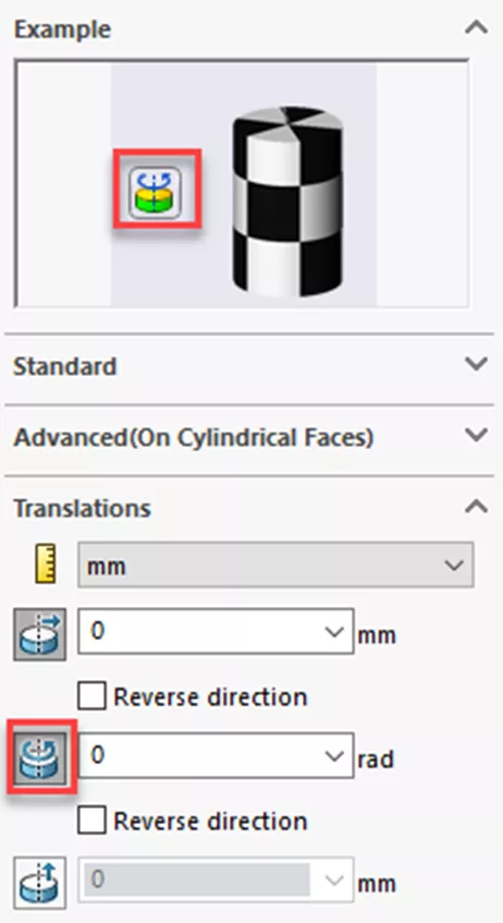
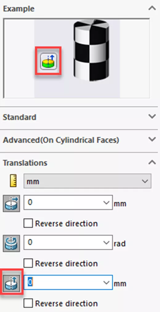
Right-click on Fixtures and choose Advanced Fixtures. In the Fixture PropertyManager, choose On Cylinder Faces.
The icon preview will cycle through animations of the three different translations: Radial, Circumferential, and Axial.
![]()
The preview for the fixture’s radial translation shows outward movement from the surface of the cylinder wall in a radial direction, but the model will still spin about the cylinder axis.
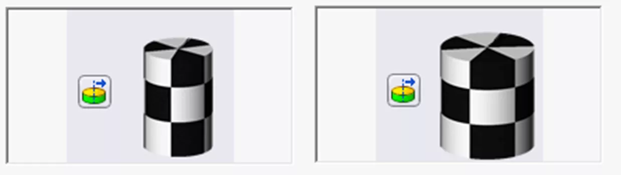
The circumferential translation preview shows the cylinder spinning about its axis. Applying a value for this translation locks down the spin of the model.
The axial translation preview shows the cylinder moving up and down along the cylinder axis. Applying a value for this translation locks movement along the axis and fully defines the constraint.
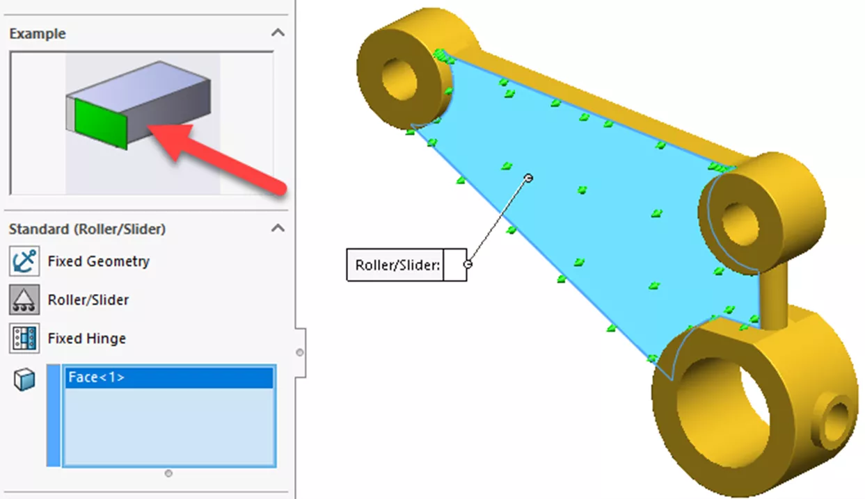
For the last example, we'll right-click on Fixtures and choose Fixed Geometry. In the Fixture PropertyManager, choose Roller/Slider and select the side wall face. The icon preview shows an animation of the model moving around in the X/Y direction but locked in the Z direction. Click OK to accept the constraint.
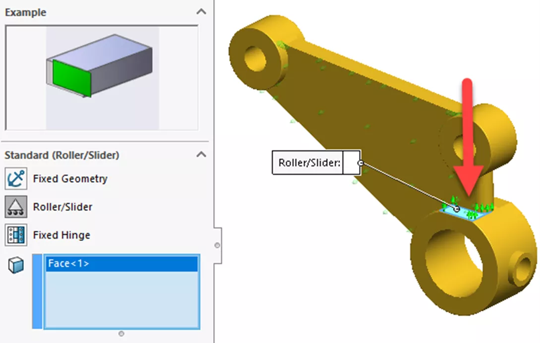
To run a SOLIDWORKS Simulation, the model must have the fixture applied in all three directions to calculate the forces.
To add a fixture in the Y direction, add another Roller/Slider fixture, and select the flat face on the larger cylinder. Click OK.
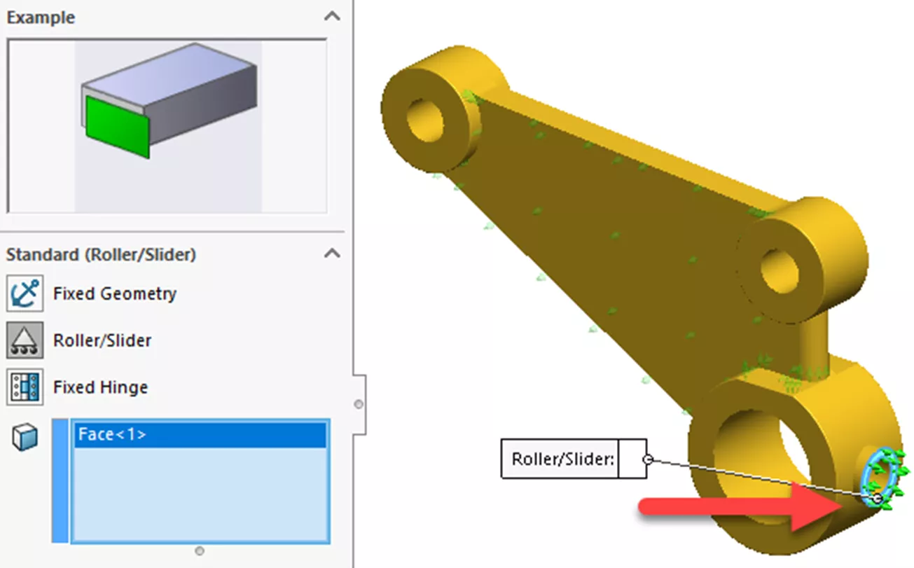
To add a fixture in the X direction, add another Roller/Slider fixture, select the flat face on the smallest cylinder, and click OK.
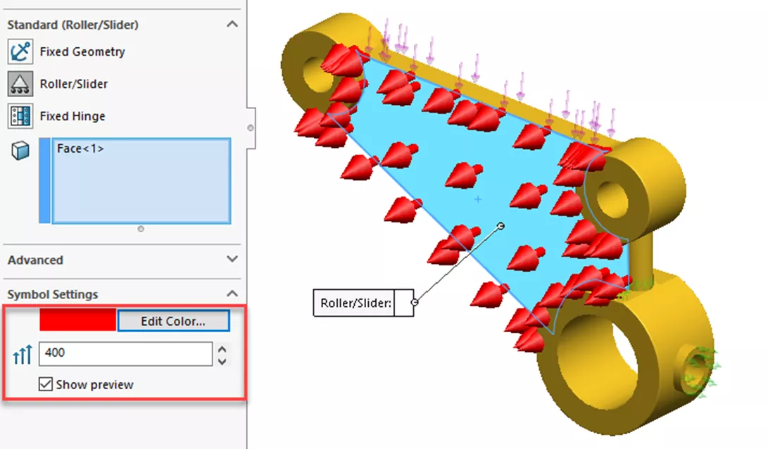
We can edit the fixtures by expanding Fixtures, right-clicking on a fixture, and choosing Edit Definition.
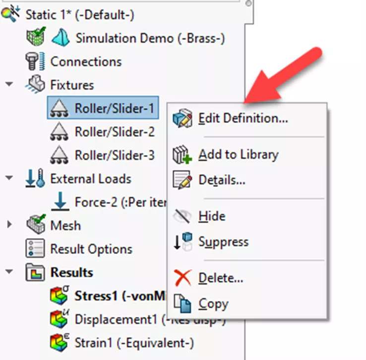
There are options to change the color of the arrows for each fixture, as well as the size of the arrows. For this example, the arrows for the first Roller/Slider fixture have been changed to red. Notice the other fixture arrow colors stay as they were. The arrow size can be adjusted with values from 20 to 500.
I hope you found this article explaining SOLIDWORKS Simulation fixture preview icons helpful. Check out more tutorials below. Additionally, join the GoEngineer Community to participate in the conversation, create forum posts, and answer questions from other SOLIDWORKS users.
Ready to take your SOLIDWORKS skills to the next level? Enroll in an official SOLIDWORKS Simulation training course. These courses range from Simulation Essentials to Advanced topics. Both in-person and online options are available.
More SOLIDWORKS Simulation Tutorials
SOLIDWORKS Simulation Iso Clipping Tool: PropertyManager Walkthrough
SOLIDWORKS Simulation CAD Conditioning with Shell Elements
Importing .CSV Files into SOLIDWORKS Simulation Design Studies
Winter Beehive Analysis Using SOLIDWORKS Flow & Thermal Simulation

About Zach Brown
Zach Brown is a certified SOLIDWORKS Expert and a Technical Support Engineer. Prior to working at GoEngineer, he spent 15 years as a mechanical designer, CAD support tech, and instructor using SOLIDWORKS. His hobbies include playing guitar, riding motorcycles, and skiing.
Get our wide array of technical resources delivered right to your inbox.
Unsubscribe at any time.