Surface Continuity in SOLIDWORKS (Part 2)
In our introduction to continuity and curvature in SOLIDWORKS (Part 1), we discussed the concepts of continuity, tangency, and curvature and used them to establish a 2-dimensional definition of C-0 (Contact), C-1 (Tangent), and C-2 (Curvature) continuity. In this blog, part 2, we will focus on these concepts in a 3-dimensional context inside of SOLIDWORKS and the tools we can use to analyze them.
Sketches to Surfaces
Below are the sketches from Part 1 that we used to discuss discontinuity, C-0 continuity, C-1 continuity, and C-2 continuity. Looking back on this, we can see that these are cumulative ideas. We begin with contact continuity (C-0) and then move onto tangent continuity (C-1). From there, we use a variable-curvature entity like a spline to establish curvature continuity (C-2).

Discontinuous Contact Continuity (C-0) Tangent Continuity (C-1) Curvature Continuity (C-2)
Continuing this discussion, we will add a dimension by making the jump from sketches to surfaces. After all, we are predominately working on 3-D in SOLIDWORKS, so it is appropriate that we focus on 3D surfaces instead of 2D sketches.
What is a surface?
As a 3D CAD software, SOLIDWORKS uses surfaces to represent the shape of our designed parts. These surfaces define the boundary of our parts and when their edges meet to create an enclosed volume, they can be defined as a solid. It is the concept of surfacing that allows us to create 3D models inside of SOLIDWORKS. In this document, the term “surface” refers to any face of a SOLIDWORKS part – not specifically to surface features and operations.
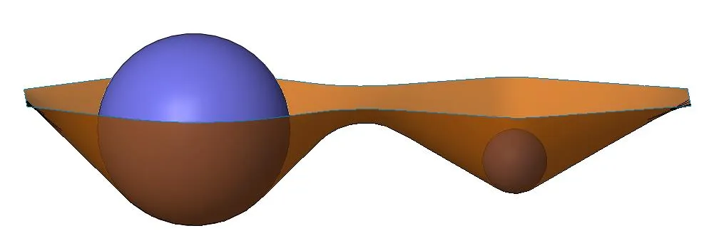
When we start analyzing these 3-dimensional surfaces, the topic of curvature and continuity can seem a little more complicated than it was in 2D. The concepts remain the same, but instead of curvature being related to the circular (2D) radius or our sketch entities, it is related to the spherical (3D) curvature of the surfaces – or in other words, the largest sphere that could be tangent to the surface at that location. Beyond that change, our rules for C-0, C-1, and C-2 continuity remain the same as they were in a 2-dimensional context.

Spheres representing the local spherical radius of a surface
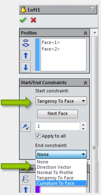
When our sketches contain C-2 continuous contours, it follows that the features/surfaces created with them will contain some level of C-2 surface continuity. However, in a few features/surfaces, there are explicit options to control the continuity between the feature/surface and what it comes in contact with. In these options, C-0 is denoted by the words “Contact” or “None” (usually chosen automatically), C-1 is referred to as “Tangent” or “Tangency to Face”, and C-2 is referred to as “Curvature” or “Curvature to Face”. In the properties of the following, you will be able to select these continuity conditions:
Features/Surfaces Containing Continuity Options
- Swept Boss/Base
- Swept Cut
- Swept Surface
- Lofted Boss/Base
- Lofted Cut
- Lofted Surface
- Boundary Boss/Base
- Boundary Cut
- Boundary Surface
- Filled Surface

We’ve now established an understanding of curvature in a 3-dimensional context. The next part of this series will focus on analyzing and identifying the continuity conditions of our parts.
Related Articles
How to Install and Troubleshoot Fonts in SOLIDWORKS
Virtual Components: Parts that Aren't Parts
How to Deactivate SOLIDWORKS if you Cannot Launch it

About GoEngineer
GoEngineer delivers software, technology, and expertise that enable companies to unlock design innovation and deliver better products faster. With more than 40 years of experience and tens of thousands of customers in high tech, medical, machine design, energy and other industries, GoEngineer provides best-in-class design solutions from SOLIDWORKS CAD, Stratasys 3D printing, Creaform & Artec 3D scanning, CAMWorks, PLM, and more
Get our wide array of technical resources delivered right to your inbox.
Unsubscribe at any time.