Virtual Components: Parts That Aren't Parts
I find that virtual components in SOLIDWORKS aren't used enough. They are awesome for imported assemblies, quick organization of assemblies, and making new parts from old ones. Virtual components have been around for some time, but many users are unaware of their functionality.
Virtual components are fully functional with one exception: you can’t make a drawing from them. To create a drawing of a component, it must be a real part, meaning it needs to have a physical file condition on the network/drive. Virtual components reside in the assembly file itself and don’t physically exist. Other than this, there are no restrictions! Here are a couple of examples in which I have used virtual components.
Imported Assemblies
Imported assemblies add workload due to having to manage not only the assembly file but all the part files that come along for the ride. In some cases, the parts come in with part names like Imported1, Imported2, Imported3. Yet, other times the part file names do not match your naming conventions making your file structure messy in most cases.
Adding a PDM system doesn’t make things any easier because now you are managing OPFs (Other People Files) through workflows and checking in/out!
One trick I’ve learned was using virtual components to ease up the file management side of things. The steps to do this are straight forward and should only add a minute or two to your workflow. Here are the steps:
- Import the assembly and save it as normal. (This will create the assembly and all the part files. I would also suggest you do this in a separate folder)
- Select all the components in the assembly, CTRL-A works great for this.
- Right-click on one of the selected components and select Make Virtual.
- BOOM! Done!
Now go to the file folder where those pesky extra parts were saved and delete them! Yep, they are not needed anymore because these parts now live inside the assembly file. While the assembly file name doesn’t have your part naming scheme, it is only one file now, making file management a cinch. The single file is a bonus to PDM users since it is easier to manage a single file through check-in/checkout and workflows.
Imported Assemblies (Part Deux)
Now that you’ve made the parts virtual, you realize that the parts are either all fixed in space or they are completely unconstrained and floating around. To top things off, motion is needed in the imported assembly, but to do this, a whole bunch of mates would be needed to get things to work correctly. With virtual assemblies, we can make this a little less tedious.
Let’s look at a clamp that was downloaded from McMaster Carr.
Here is what it looks like right after importing. Note that all the parts are floating. DO NOT TOUCH ANYTHING!
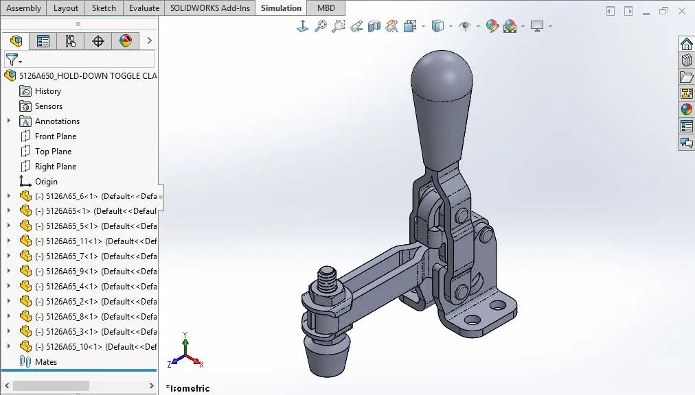
Since everything is floating, hit CTRL-A and fix everything, this way nothing gets misaligned.
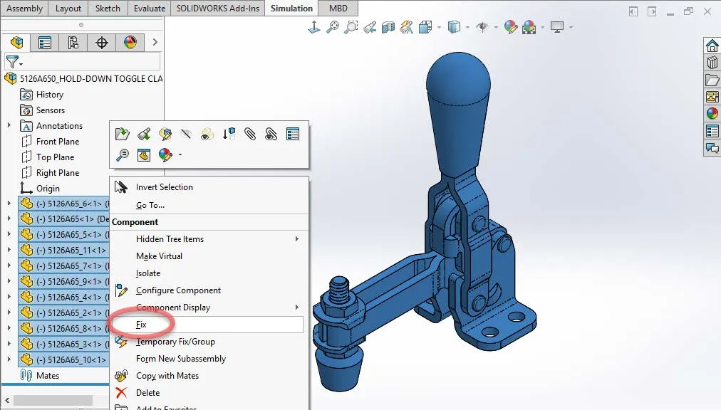
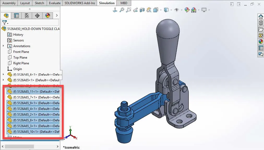
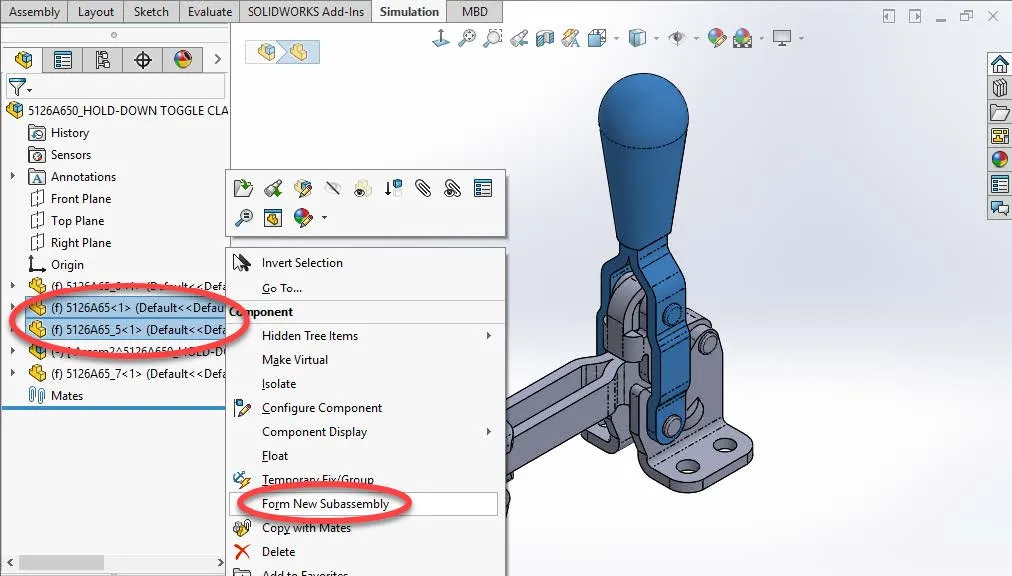
Now identify the groupings of parts. Here I selected all the parts for the arm of the clamp.
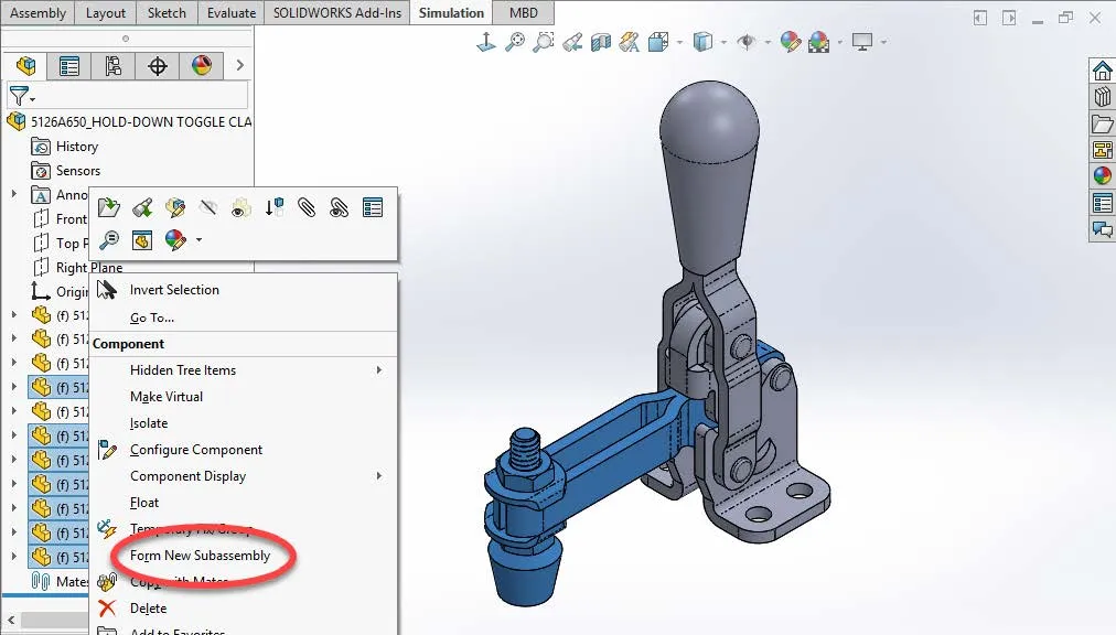
Once the parts are selected, right-click on one of them and select Form New Sub-Assembly.
Next, repeat the same for the handle components.
Mating the new virtual sub-assemblies and original components still needs to happen but we have reduced the top-level components from eleven down to four! In the clamp arm itself, it would take about 12-14 mates to make it all act as one piece. Now it’s a sub-assembly and acts as one piece without the mates.
Here is what the Assembly Component Manager looks like after completing the mating process for the whole assembly.
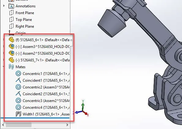
Seven mates and this process took about five minutes from beginning to end. Et Viola!
Virtual components have been around for a while, and I don’t think that they get their due. Hopefully, these examples have cracked open a door to some possible usage of virtual components in your workflow. Thank you for taking a moment to learn more about SOLIDWORKS virtual components, and be sure to subscribe for more SOLIDWORKS tips and tricks.
More SOLIDWORKS Tutorials
SOLIDWORKS Custom Property Tab Builder: Step-by-Step Guide

About Ryan Cole
Ryan Cole is an Elite Sr. Applications Engineer and Trainer at GoEngineer, with 24+ years of experience in design engineering specifically using the SOLIDWORKS line of products. Ryan has utilized SOLIDWORKS since 1995, when he became one of the first SOLIDWORKS users in Michigan. He has a long history of supporting and using SOLIDWORKS for mechanical, structural design, and FEA in Automotive, Robotics, Emergency Vehicles, Defense, Custom RV Chassis’, Aerospace, and manufacturing line development. Along the way, Ryan has worked in roles as a Sr. Designer, Lead Engineer, FEA Engineer, and Product Manager. He is well versed in various material properties and engineering/manufacturing requirements, such as engineering change, design review, supplier development and support, ASTM, GD&T, APQP, QS9000, TS16949 and implementation of PDM systems. First exposed to this industry 29 years ago, Ryan’s grandfather, Mr. Cole, taught him how to draft on a board the old-school way, with a pencil and scale, when he was in his teens. He moved to the modern technology of 2D design shortly after, and began 3d design the first time he was employed by a SOLIDWORKS VAR more than two decades ago. Ryan’s work on large assemblies can be seen in Visualize, as his model of the LEGO Millennium Falcon was chosen for the splash screen. In his spare time he enjoys hiking, swimming, reading sci-fi, studying astronomy, physics, and modeling Legos in SOLIDWORKS. He pretends to enjoy doing his wife’s honey-do lists on the weekends. They have been together almost 30 years, with one child, Gracie, and 2 guinea pigs. They enjoy exploring nature, science, history, and working on their new house together. Certifications: Elite, CSWA, CSWP, and CSWE
Get our wide array of technical resources delivered right to your inbox.
Unsubscribe at any time.