How to Use the Import Diagnostics Tool in SOLIDWORKS
When importing non-native files into SOLIDWORKS, we sometimes encounter faulty geometry that must be corrected after opening the model. These geometry faults are typically introduced during the export process, not the import process. In this article, learn how to use the Import Diagnostics tool in SOLIDWORKS to help address these faults.
Imported Part Files
When we open generic 3D files in SOLIDWORKS (e.g., .stp, .STEP, .igs, .IGES, .x_t, .sat, etc.), it is good practice to run the Import Diagnostics tool to give the file a once-over and let SOLIDWORKS attempt to automatically repair these faults.
Note: 3D Interconnect must be disabled when you open your file in order to run Import Diagnostics (Tools > Options > Import > 3D Interconnect)
If you already opened the part with 3D Interconnect on (your Feature Tree will have this icon): ![]()
You will need to dissolve it (right-click > ‘Dissolve Feature’)
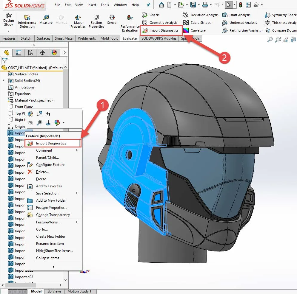
If you are not prompted to run the Import Diagnostics tool after importing a generic 3D file, this message box may have been dismissed. In this case, right-click an imported body and select ‘Import Diagnostics’ or find it in the CommandManager (Evaluate tab > ‘Import Diagnostics’):
Note: You must not have any features in the model tree, only imported bodies or surfaces.

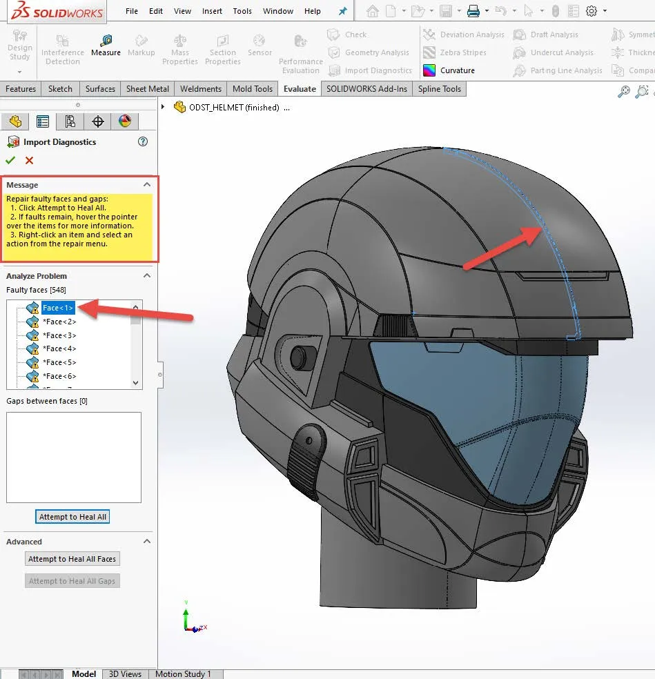
The message in the Import Diagnostic PropertyManager provides information on how to use the tool. When a faulty face, edge, or gap is selected, it will highlight in the graphics view.
- Click 'Attempt to Heal All'. This is the easiest way forward. SOLIDWORKS will attempt to analyze and repair.
- If faults remain, hover the cursor over the items for more information.
- Right-click on any remaining items and attempt to repair them one by one.

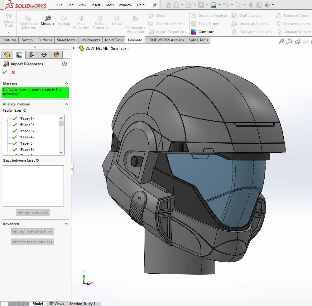
If you’re lucky, SOLIDWORKS will repair all of the faulty geometry for you! Look for the green message in the PropertyManager that states: ‘No faulty faces or gaps remain in the geometry.’

If the Import Diagnostics tool is not able to repair the model, then you will need to manually repair the remaining faces, edges, and gaps.
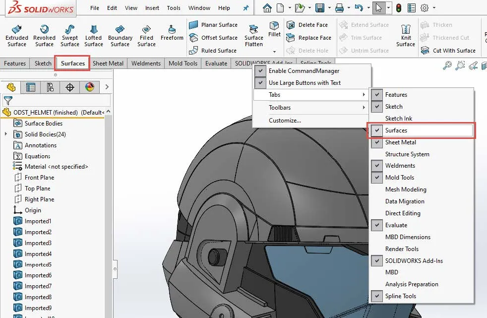
To repair most faults, you will need to use the SOLIDWORKS Surfacing tools. Every license of SOLIDWORKS has access to these tools, and you can show them in the CommandManager by right-clicking any existing tab and activating the Surfaces tab.

Here are a few resources covering the most commonly utilized surfacing tools to repair faulty geometry on imported parts:
Video: SOLIDWORKS Quick Tip – Advanced Surface Repair
Video: SOLIDWORKS – Heal Edges
Imported Assembly Files
If you have imported a generic 3D file into an assembly, perform these steps:
-
Import the file.
-
In the assembly tab, go to the Evaluate tab > use the ‘Check’ command.
-
Check the file for faults.
-
Select the faults (one by one) listed within the ‘Result list’ in the ‘Check Entity’ dialog box. The location of the faults are highlighted in the graphics area.
-
You can now determine the component(s) that contain the geometrical errors and use the steps mentioned above to repair them.
I hope you found this article helpful. Check out more SOLIDWORKS tips and tricks below.
More SOLIDWORKS Tutorials
How to Remove the SOLIDWORKS Toolbox Flag

About Preston Ruff
Preston Ruff is a Technical Support Engineer and Certified SOLIDWORKS Instructor based out of our Headquarters in Salt Lake City, Utah. He earned a Bachelor’s degree in Manufacturing Engineering Technology from Brigham Young University and is a Certified SOLIDWORKS Expert. For many years, Preston has been passionate about CAD design, 3D printing, additive manufacturing, and being involved with STEM education. He joined the GoEngineer family in 2017.
Get our wide array of technical resources delivered right to your inbox.
Unsubscribe at any time.
