Introduction to Continuity and Curvature in SOLIDWORKS (Part 1)
Throughout SOLIDWORKS, we often see options to make things “tangent” or “curvature continuous” (or other similarly-stated options). These options show up in sketching and solid/surface feature creation, but their mathematical definition is less apparent. Learning to manage your continuity and curvature properly in SOLIDWORK is integral to creating designs with high-quality form factors. In this article, we will take a dive into the mathematical nature of continuity and curvature and how they are employed in the SOLIDWORKS environment.
Types of Continuity
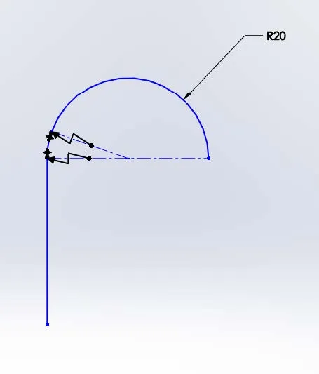
Orders of continuity present in SOLIDWORKS are as follows: contact continuity (C-0), tangent continuity (C-1), and curvature continuity (C-2). To demonstrate these concepts, we will take a look at how they apply to 2-D sketch entities – specifically between an arc and a line.
Contact Continuity (C-0)
The word “continuous” is defined by Merriam-Webster as “marked by uninterrupted extension in space, time, or sequence”. For our purposes, we will see continuity as simply having one entity start where the previous entity ends. In the above images, the line and arc with a gap between endpoints are discontinuous. In the other set, the arc begins right where the line ends. This is referred to as contact or ‘C-0’ continuity.
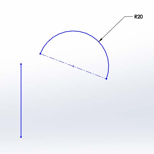
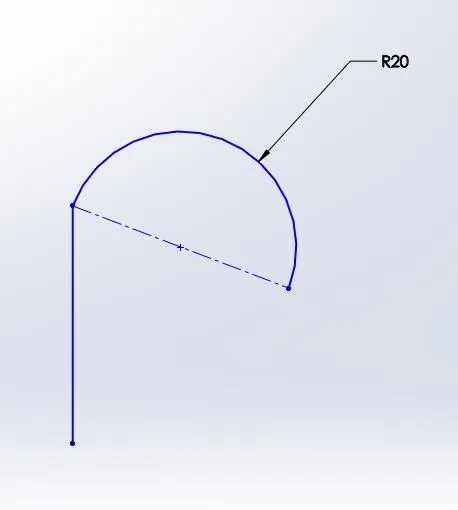
Discontinuous C-0 Continuity
Tangent Continuity (C-1)
The next order of continuity exhibits contact continuity (C-0), but it also maintains path trajectory continuity. In other words, at the vertex between the two entities, the entities are instantaneously parallel. This is normally accomplished by a tangent relation in sketching.
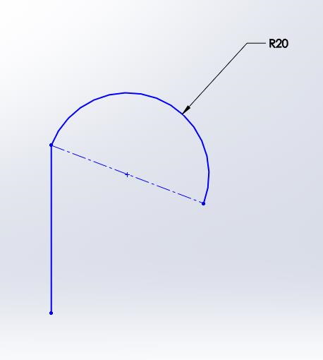
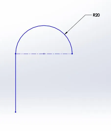
C-0 Continuity C-1 Continuity
Curvature Continuity (C-2)
Curvature continuity builds on top of C-0 and C-1 continuity, meaning that it maintains contact continuity and tangent continuity, but it also maintains curvature continuity. The following section will discuss the definition of curvature and curvature in the context of our line and arc example.
Curvature
Intuitively, the concept of curvature is most likely already understood. Saying region A of the spline pictured below is “more curved” than region B would hardly spark protest.
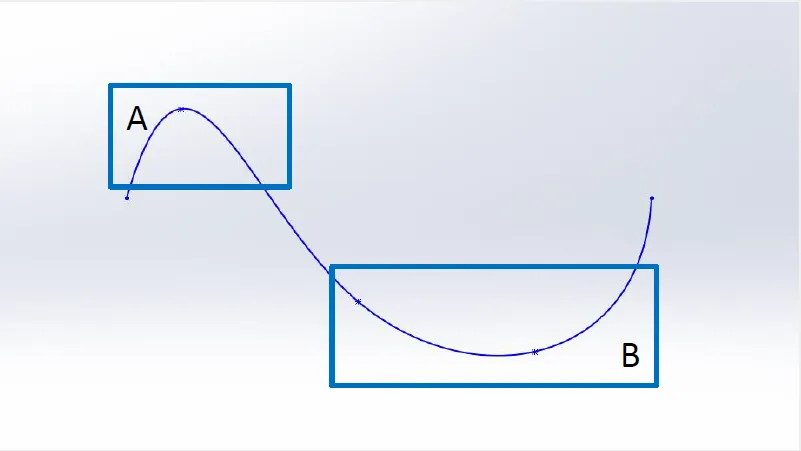
Spline with varying degrees of curvature
However, mathematically defining curvature may be less obvious. If we’re going to be analyzing curvature, a quantitative definition is going to be necessary. This definition is actually quite simple: curvature (k) is equal to the inverse of the radius (r).
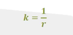
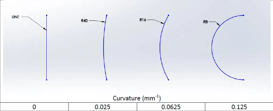
The inverse relationship between radius and curvature can be seen by watching an arc as its radius as it approaches infinity. If you look at the figure below from right to left, the radius approaches infinity. Concurrently, the curvature approaches zero. The line has a curvature of zero, which intuitively makes sense, and it has an infinite radius.
Ensuring curvature continuity can have a huge impact in both the look and the feel of a product. In the automotive industry, this is known as “Class A Surfacing”. Maintaining C-2 continuity conveys a much better looking reflection on a car’s clear coat. It also makes for a much smoother feel in consumer products.
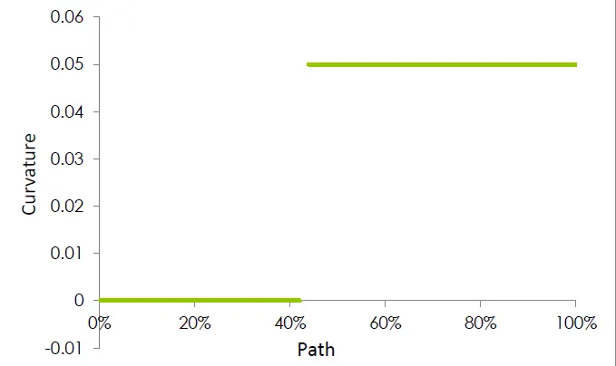
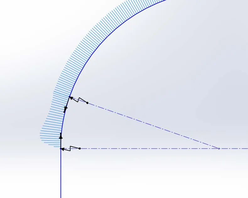
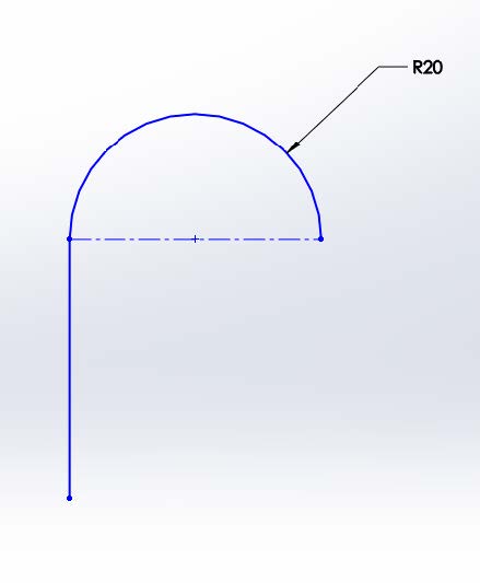
Looking back at our line and arc example, we will see that our C-1 example cannot achieve C-2 continuity. Because the line has a constant curvature of zero and the arc has a constant curvature of .05 (radius of 20), a graph of the curvature along the path will show a discontinuity.
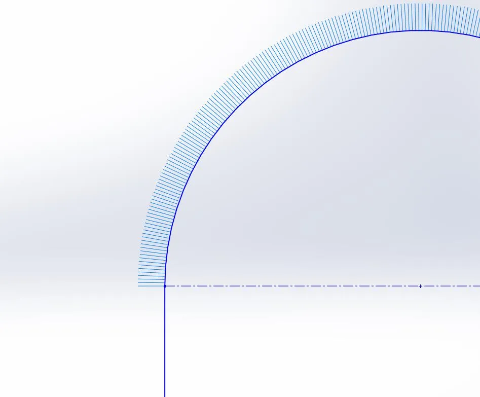
Line and arc sketch with curvature combs
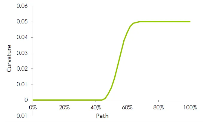
To bridge this gap we will use the sketch entity from the beginning of our curvature discussion: the spline. As we saw earlier, a spline can change curvature within the same sketch entity. It is also curvature continuous throughout. Adding a curvature continuous relation at the vertex between the line and the spline, and the spline and the arc will ensure C-2 continuity at each vertex. (Note: C-2 continuity can also be achieved by using a fit spline.) The resulting sketch and graph are as follows.
Spline bridging the curvature gap
C-1 Continuity C-2 Continuity C-2 Continuity
Once we have a curvature continuous sketch, the feature we make with this sketch will have C-2 continuous surfaces as seen below. In Continuity and Curvature in SOLIDWORKS (Part 2), we will look into 3-Dimensional examples of C-0, C-1 and C-2 continuity and the SOLIDWORKS tools we can use to analyze the continuity and curvature of our models.
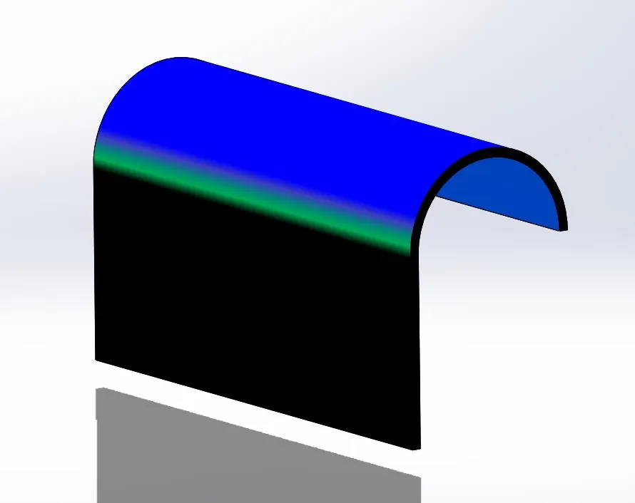
Thin feature extrusion of our sketch with curvature display enabled
Our Latest SOLIDWORKS Tips and Tricks
Using the Move/Copy Body Feature in SOLIDWORKS
Searching for Functions in SOLIDWORKS 2021
How to Install and Troubleshoot Fonts in SOLIDWORKS

About GoEngineer
GoEngineer delivers software, technology, and expertise that enable companies to unlock design innovation and deliver better products faster. With more than 40 years of experience and tens of thousands of customers in high tech, medical, machine design, energy and other industries, GoEngineer provides best-in-class design solutions from SOLIDWORKS CAD, Stratasys 3D printing, Creaform & Artec 3D scanning, CAMWorks, PLM, and more
Get our wide array of technical resources delivered right to your inbox.
Unsubscribe at any time.