SOLIDWORKS Simulation Shell Element Virtual Interference
Shell elements are very useful and can make your SOLIDWORKS Simulation analysis run faster and more accurately than if solid elements were used in certain situations. These situations are when the model has a very large surface area when compared to the thickness. The general rule of thumb is a 10 to 1 ratio of surface area to thickness of a model.
For example, sheet metal models are generally large plate-like structures with large surface areas and thin thicknesses across the model. This is a perfect shell element situation because, in order to obtain accurate data on a sheet metal part like the one described above, the analyst using solid elements needs to create a fine enough mesh to get at least two mesh elements across the thickness of the part throughout the sheet metal model.
This can result in very large mesh densities (over 100,000 elements) that can take hours or sometimes days to run and obtain results that may or may not be accurate if the mesh still was not dense enough to accurately capture the thickness of the model.
If however, the analyst uses shell elements instead of solid elements to mesh this sheet metal part, the mesh is created in a 2D plain rather than throughout the part. This allows the analyst to greatly increase the mesh density of the shell mesh while keeping the mesh density of the entire part low.
The program then needs to interpolate the stresses and displacements seen through the thickness of the model mathematically. This can be easily done in the sheet metal example above because when the surface area of the model is so much greater than its thickness the stress and displacements seen through the thickness are assumed linear.
The analyst using shell elements however needs to be aware of virtual interferences. This type of interference can be difficult to detect if you do not know what you are looking for.
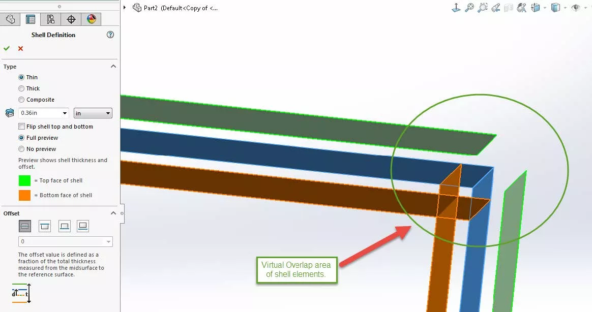
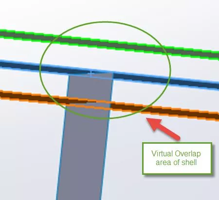
Virtual interferences happen with some shell elements at sharp corners where the shell elements are continuous but not co-planar. The shell elements meet at these sharp corners and seem fine, but when the simulation is being run and the thickness of the plate that the shell element is representing is interpolated there is a virtual overlap of results in these sharp corner areas, and these results should not be accepted as accurate. Examples of virtual interferences are provided below.
What to do with Virtual Interferences
Once a virtual interference has been identified, the analyst must make some decisions. If the results in the corner area of the virtual interference are not important to the overall analysis of the model being simulated, then these areas can just be ignored.
If however, these areas are important (like if the analyst suspects this area to be where a high-stress concentration is) then the shell elements that make up this corner area should be changed to solid elements and a fine local mesh should be applied to the area around the corner being analyzed.
Performing this operation should not increase the studies mesh density too much because only a small portion of the overall model is being made into solid elements and it will remove the virtual interference from the corner being analyzed so that accurate results can then be obtained from this area.
Learn More About SOLIDWORKS Simulation
Define Shell Elements by Selected Faces in SOLIDWORKS Simulation
Using Sheet Metal Bodies in SOLIDWORKS Simulation
SOLIDWORKS Simulation Elements: Solid vs. Beam Results
Why Use Hex Elements in your FEA
Performing a Thermal Stress Analysis in SOLIDWORKS Simulation

About Taran Packer
Taran is a SOLIDWORKS Simulation Technical Support Specialist at GoEngineer. He has a Bachelor’s degree in Biomedical Engineering from the University of Utah. Taran enjoys learning about different tools in SOLIDWORKS Simulation, Flow Simulation, and Plastics.
Get our wide array of technical resources delivered right to your inbox.
Unsubscribe at any time.