Performing a Thermal Stress Analysis in SOLIDWORKS Simulation
Thermal stress analyses can be performed in various ways using the SOLIDWORKS Simulation and SOLIDWORKS Flow Simulation packages. A thermal stress analysis entails defining thermal conditions and analyzing the stresses that develop in components due to thermal expansion. This guide will illustrate the different ways of performing thermal stress analyses.
Linear/Nonlinear Static – Thermal Stress
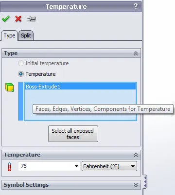
Thermal stress analysis can be performed using the Linear Static and Nonlinear Static modules included in SOLIDWORKS Simulation/SOLIDWORKS Simulation Premium. One of the load types available in a static study is temperature. This allows a user to specify a specific temperature on different entity types.
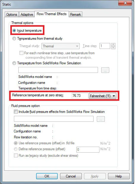
The software uses this temperature boundary condition in concert with a static study property (Flow/Thermal Effects Tab: Reference temperature at zero strain). The input temperature option is set to specify the solver to use the temperature boundary conditions defined in the static study for the thermal stress calculation.
Depending on the temperature specified in the temperature boundary condition, the component will either expand (if the temperature is above the reference temperature of zero strain value) or contract (if the temperature is below the reference temperature at zero strain value). Based on this temperature difference, the software will calculate the model deflection that occurs using the thermal expansion coefficient material property. The software will then calculate strain. From strain, the software will then calculate stress.
SOLIDWORKS Simulation Thermal Module
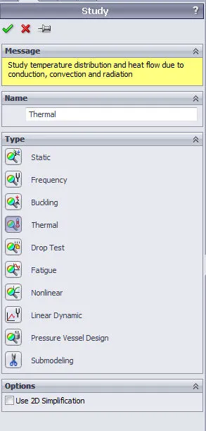
The thermal module included in the SOLIDWORKS Simulation Professional product suite allows one to study temperature distribution and heat flow in a mechanism due to conduction, convection, and radiation effects. Outputs from this module can be coupled with a linear static study to compute thermal stress.
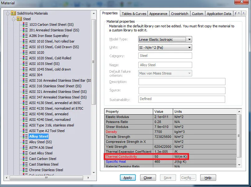
Conduction effects are automatically taken into account during the analysis and are attributed to the thermal conductivity material property.
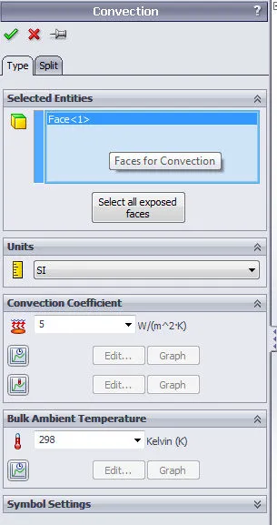
Convection effects (to emulate surface cooling or heating caused by a surrounding fluid) are defined using a surface boundary condition. The presence of a fluid is specified with a Convection Coefficient and Ambient Temperature input. The value for the convection coefficient can be modified using time or temperature curve while the value of the ambient temperature can be adjusted using a time curve.
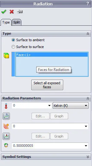
Radiation effects (heat transfer caused by electromagnetic waves) are defined using a surface boundary condition. The presence of radiation is accounted for by specifying an Ambient Temperature, Emissivity, and View Factor input. The value of the ambient temperature can be modified using a time curve, while the value of emissivity can be adjusted using a temperature curve.
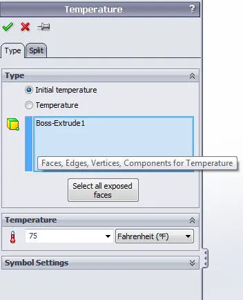
Thermal energy can be applied by specifying a Temperature, Heat Flux, or Heat Power boundary condition to model entities. The initial temperature option in the Temperature boundary condition is used to specify the initial temperature of entities when used in a Transient Thermal analysis.
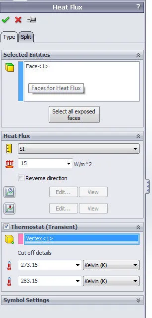
Heat flux can be applied to model surfaces. The value of heat flux can be modified by specifying a temperature or time curve. If the transient option is enabled in the Thermal study properties window, the thermostat option can be enabled and a model vertex can be selected. When the temperature of this vertex goes above the upper bound temperature, the heat flux turns off. When the temperature of this vertex goes below the lower bound temperature, the heat flux turns on.
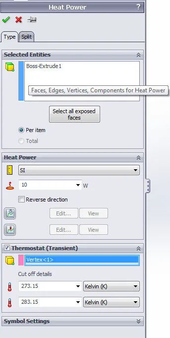
Heat power can be applied to model entities. The value of heat power can be modified by specifying a temperature or time curve. If the transient option is enabled in the Thermal study properties window, the thermostat option can be enabled and a model vertex can be selected. When the temperature of this vertex goes above the upper bound temperature, the heat power turns off. When the temperature of this vertex goes below the lower bound temperature, the heat power turns on.
Once a thermal analysis has been completed, the output can be coupled to a linear or nonlinear static study to compute thermal stress. This is achieved by setting the appropriate options in the linear or nonlinear static study properties window.
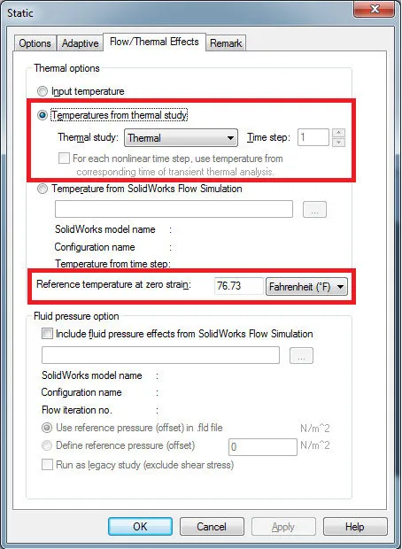
The temperature from the thermal study option is used to designate which thermal study to link the linear static study. The temperature results from the thermal study are then applied to the model as a boundary condition. Results can be taken from a specific time step if a transient thermal analysis was run. The reference temperature at zero strain option is used to compute the deflection induced in the model by thermal expansion as stated in the Linear/Nonlinear Static – Thermal Stress section of this guide. The deflection results are used to calculate strain and then stress.
SOLIDWORKS Flow Simulation
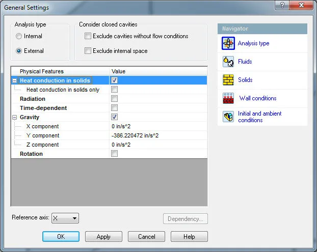
SOLIDWORKS Flow Simulation can be used to analyze the heat transfer mechanism that occurs between solid and fluid entities by modeling up both the solid and fluid spaces. Gravity can be enabled to handle natural convection thermal analysis (buoyancy effect).
Thermal energy can be inputted into the system in a number of ways in SOLIDWORKS Flow Simulation. The main thermal boundary conditions include Surface and Volume Heat Sources.
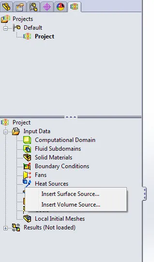
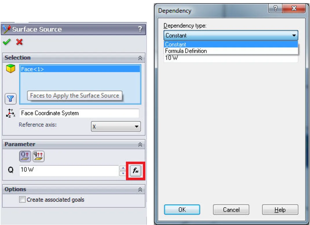
Surface Heat Sources can be applied to model surface entities. The heat source value can be applied as a heat generation rate or surface heat generation rate. The “fx” button can be selected to modify how the heat source value is evaluated.
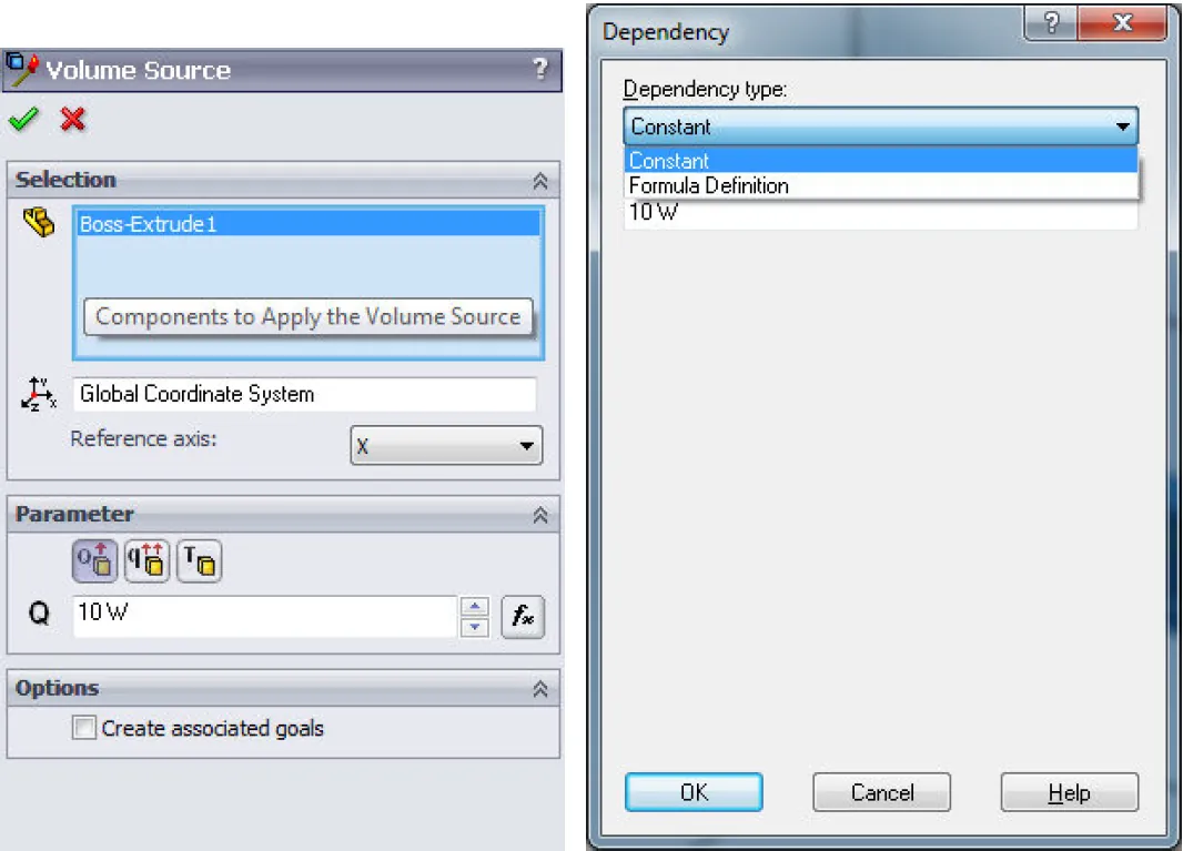
Volume Heat Sources can be applied to model entities. The heat source value can be applied as a heat generation rate, a volumetric heat generation rate, or as a temperature. The “fx” button can be selected to modify how the heat source value is evaluated.
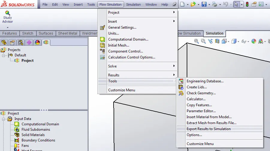
After the SOLIDWORKS Flow Simulation analysis has been run, the outputs of the analysis can be exported to a SOLIDWORKS Simulation study to perform a thermal stress analysis (Linear Static or Nonlinear Static: Flow Simulation > Tools > Export Results to Simulation).
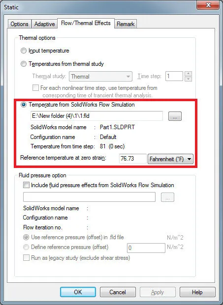
The Flow/Thermal Effects tab in the static study property window is used to link the static study to the specified SOLIDWORKS Flow Simulation analysis. The reference temperature at zero strain option is used to compute the deflection induced in the model by thermal expansion as stated in the Linear/Nonlinear Static – Thermal Stress section of this guide. The deflection results are used to calculate strain and then stress.
SOLIDWORKS Simulation Tutorials
7 Steps to Simulate a Drop Test in SOLIDWORKS Simulation
No Penetration Contact Set Setup Tips
Frequency Study Plot with SOLIDWORKS Simulation
![]()
About GoEngineer
GoEngineer delivers software, technology, and expertise that enable companies to unlock design innovation and deliver better products faster. With more than 40 years of experience and tens of thousands of customers in high tech, medical, machine design, energy and other industries, GoEngineer provides best-in-class design solutions from SOLIDWORKS CAD, Stratasys 3D printing, Creaform & Artec 3D scanning, CAMWorks, PLM, and more
Get our wide array of technical resources delivered right to your inbox.
Unsubscribe at any time.