CAMWorks Toolpath Allowances Explained
In CAMWorks, there are several ways to add allowances between the tool and the material. You can use it to your advantage to give the part a much tighter tolerance and better look by not seeing as many tool marks. There are many customizable options when it comes to allowances which we will go over.
Note: This is not the same as using a tool offset or CNC compensation.
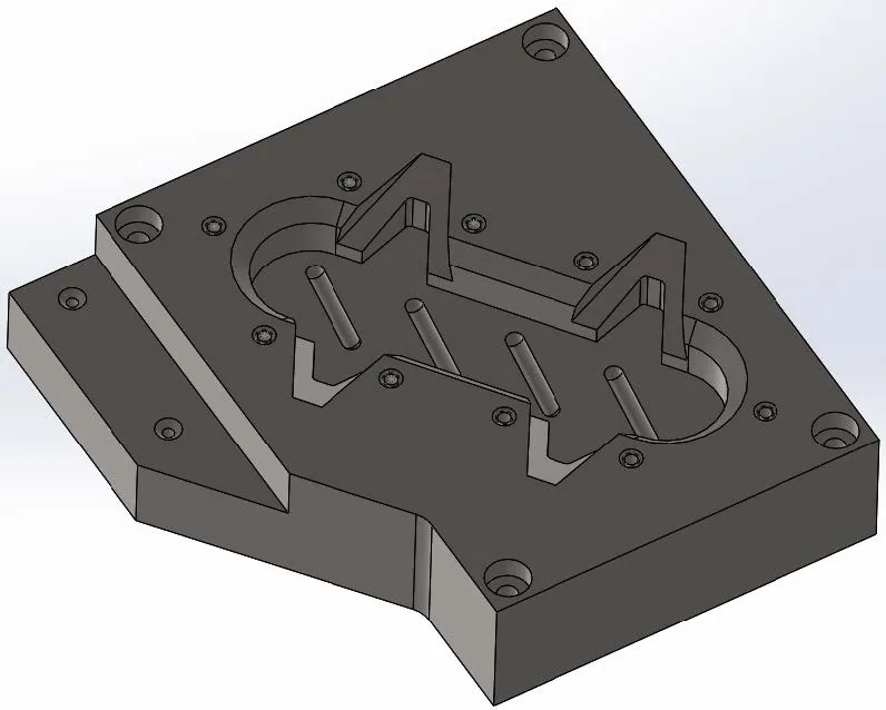
I will use this part to show you multiple ways we can use allowances to our benefit. Let’s start with where to access the settings for allowances that are related to finish passes.
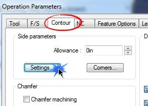
When you select Edit Definition on an operation this box will appear and under the Contour tab there is a section called Side parameters and you will select Settings.
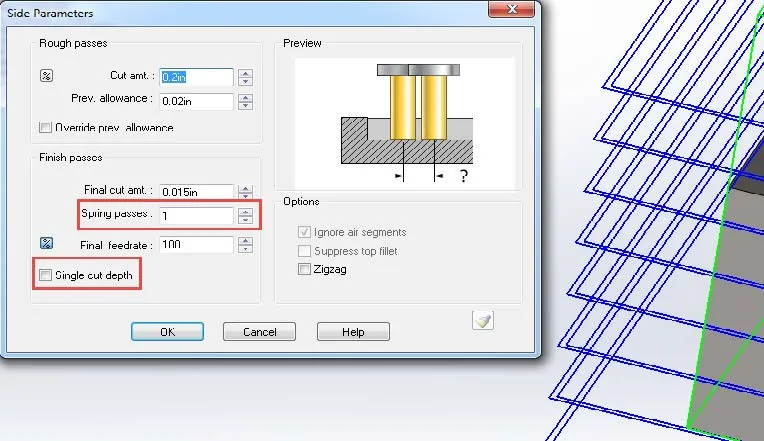
This box will pop up, and for this tutorial, we will focus on the Finish passes section.
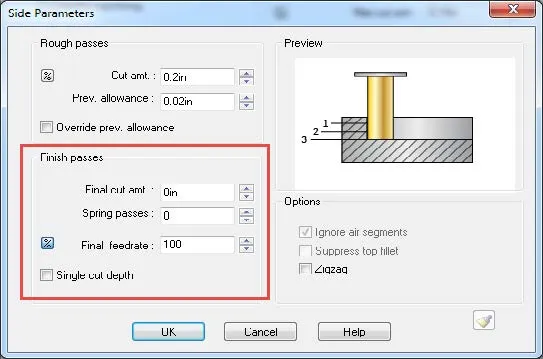
- Final cut amt is asking what amount of material do you want to remove on the final cut
- Spring passes is a feature that will repeat the final pass as many times as you specify
- Final feedrate is adjustable if you would like to speed up or slow down the final pass
- Single cut depth if selected, it will make one final pass at the lowest depth rather than moving to the specified “Final cut amt” on each pass.
This photo shows what the toolpath looks like if you enter in a Final cut amt of .015". You will notice Single cut depth is selected so the final .015” pass will be taken all at once after the regular passes. You will see at the last toolpath there are two paths, one is the regular path that is being cut .015” away from the actual finished size of the part and the last one is .015” closer to the part which is the Final cut amt we specified which will give us a cleaner looking and more precise part. Even though Spring pass is (1), we won’t see another tool path for it but it will follow the final pass one more time making sure to clean any deflection that there might be.
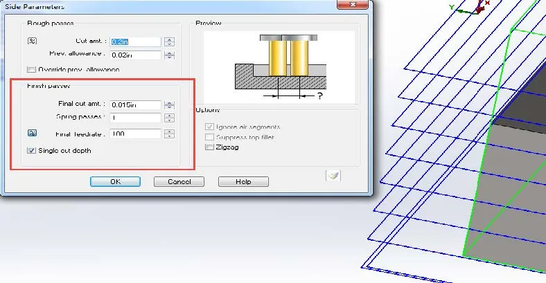
This photo will show what the toolpath looks like when Single cut depth is not selected. That means that the Final cut amt will be cut at each depth, making one normal pass then a finish pass before going to the next depth. If you add a Spring pass the tool will make an additional pass on each cut.
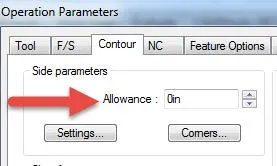
Let’s look at a different type of allowance. This allowance is located directly in the Contour tab in the top left corner in the Side parameters section and controls the allowance or offset of the tool from the part.
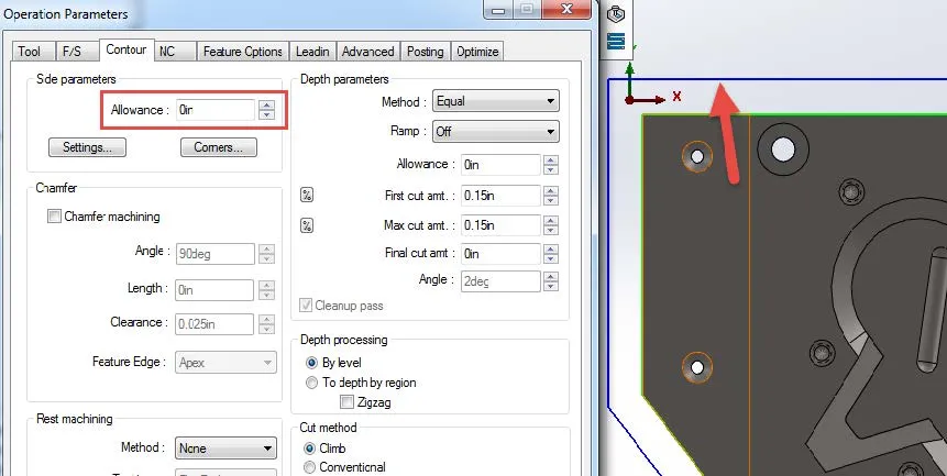
By default, this will be “0” meaning that no side allowance will be added. Below is a photo showing the toolpath using the default “0” allowance which means there will be no change.
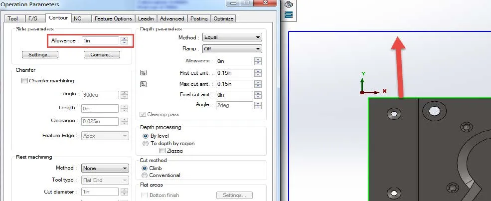
The next photo shows the drastic change when the allowance is changed to 1”. You will see that it moves further away from the part thus creating an allowance of 1”. Normally you wouldn’t use such a large allowance; this amount was for demonstration purposes only. You can also enter a negative allowance which would bring the tool closer to the part.
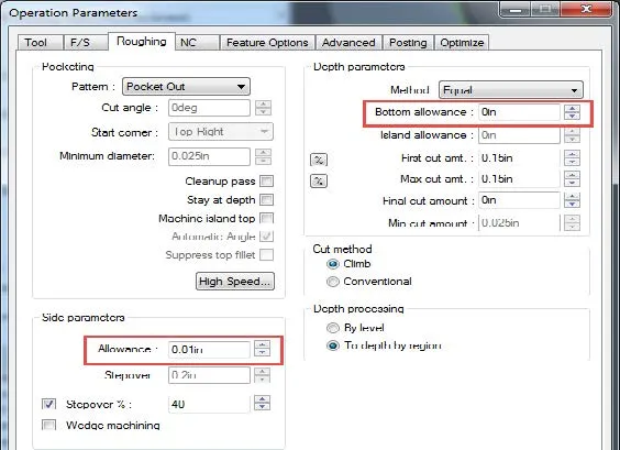
Lastly, let’s take a look at the allowances available to us for a Roughing operation. You are able to add an allowance for both side and depth. By default, the Side allowance is set to “.01in” and Bottom allowance “0”. This is useful when roughing areas that need to maintain very tight tolerances since you may opt to leave slightly more material for the Contour operation and take less material at a time until the tolerance is met. This photo shows where the allowance settings are located in a Roughing operation.
I hope you found this CAMWorks toolpath allowances tutorial helpful. More CAMWorks tutorials are listed below.
Learn More about CAMWorks
Creating a ThreadMill Feature in CAMWorks
CAMWorks Milling Features and Allowable Operations
Importing the Technology Database in CAMWorks

About Kregg Egan
Kregg is a CAMWorks and SOLIDWORKS specialist based in Salt Lake City, UT. Prior to joining GoEngineer, Kregg was a machinist for a medical research company. In that role, he was able to machine parts that were used to make life-saving medical devices which he found to be very rewarding. In his off-time, he enjoys riding motorcycles and tinkering on small projects.
Get our wide array of technical resources delivered right to your inbox.
Unsubscribe at any time.