Testing Aquarium Filters Using SOLIDWORKS Flow Simulation
For decades, I have been an aquarist. Like most hobbyists, I started simple, and put together a community aquarium with a variety of fish that were compatible with one another, with a standard aquarium filter. Later, I started breeding specific fish. In breeding aquariums, the filter system needs to be a bit different so that the young fish (the fry) don't get sucked into the filter. I knew that the placement of the filter would impact its flow efficiency, but I wasn't exactly sure to what extent. (Even the filter manufacturer didn't provide this information.) So, I decided to investigate this by creating the aquarium and filter system assembly in SOLIDWORKS and then running a simulation of each type of filter system in different positions.
Sponge Filters: How They Work
There are two basic sponge filter systems for aquariums that I decided to consider: a weighted single-sponge and a dual-sponge.
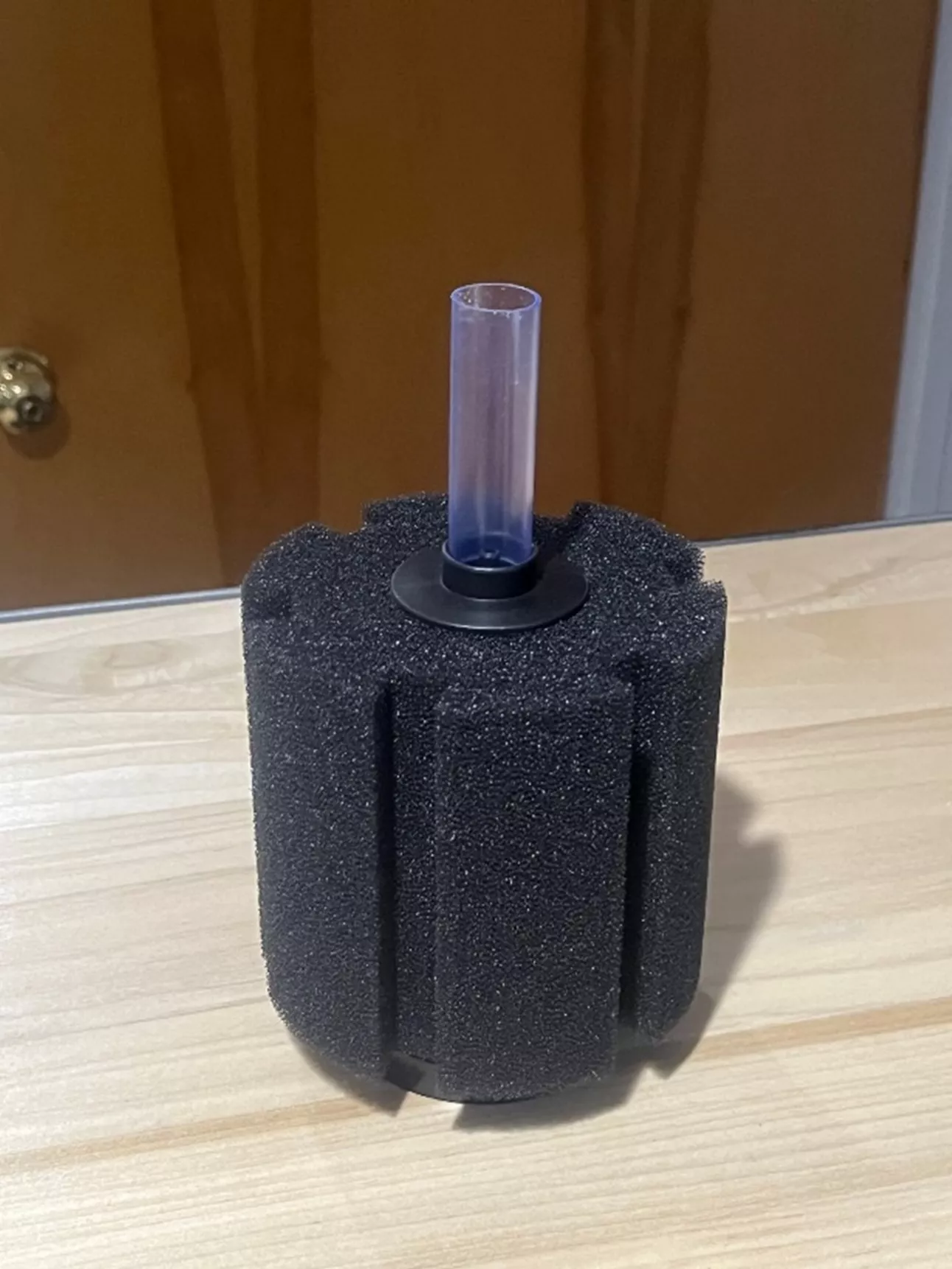
Weighted Single-Sponge Filter System
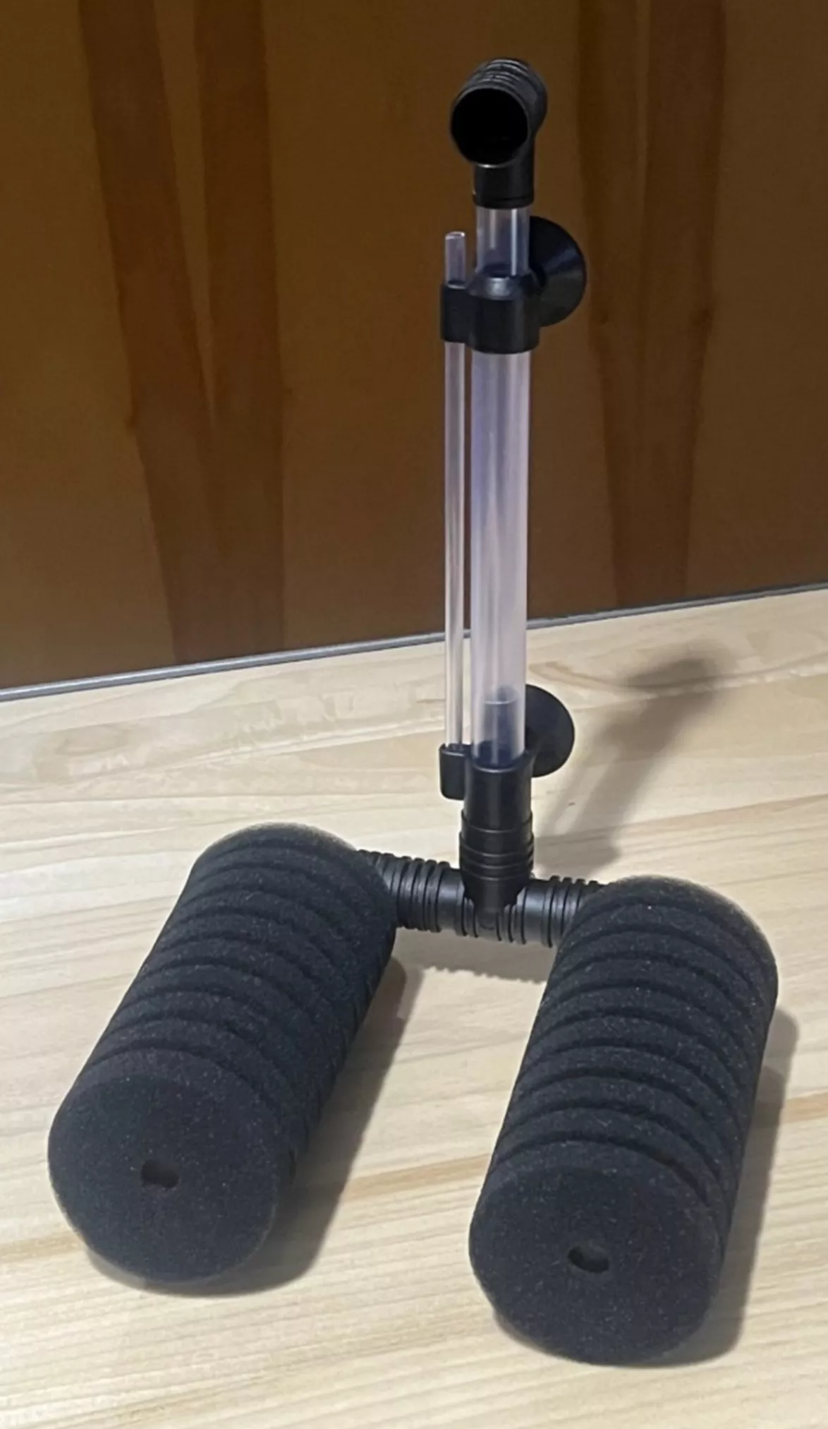
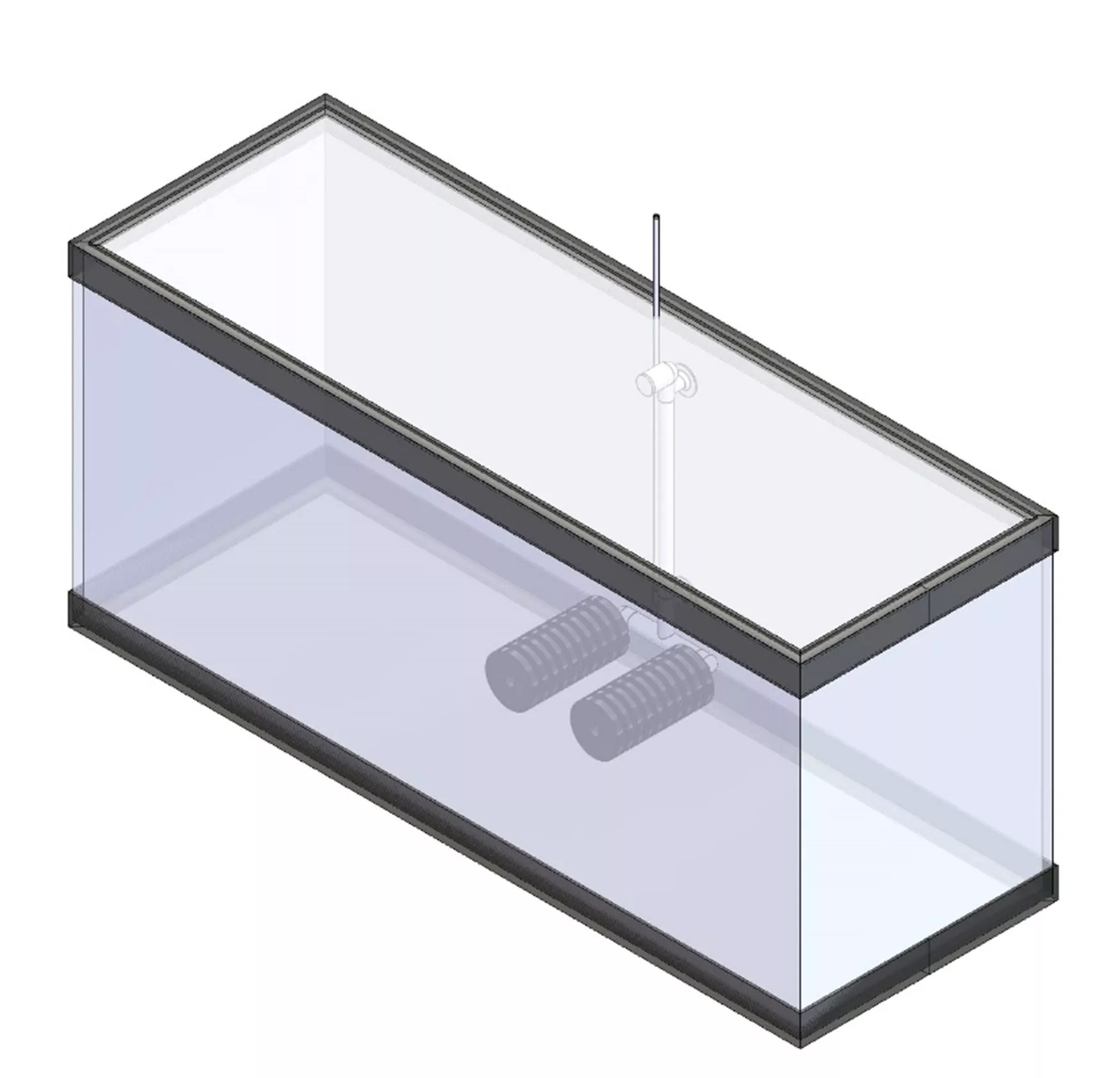
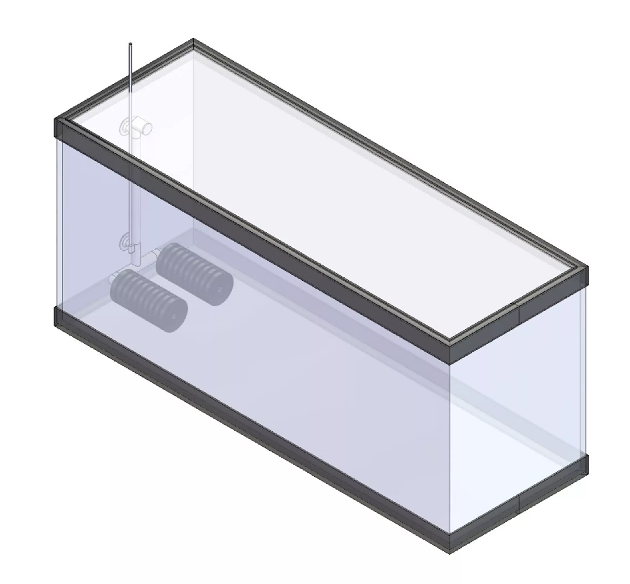
Dual-Sponge Filter System
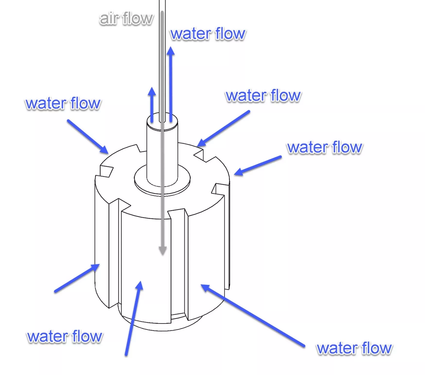
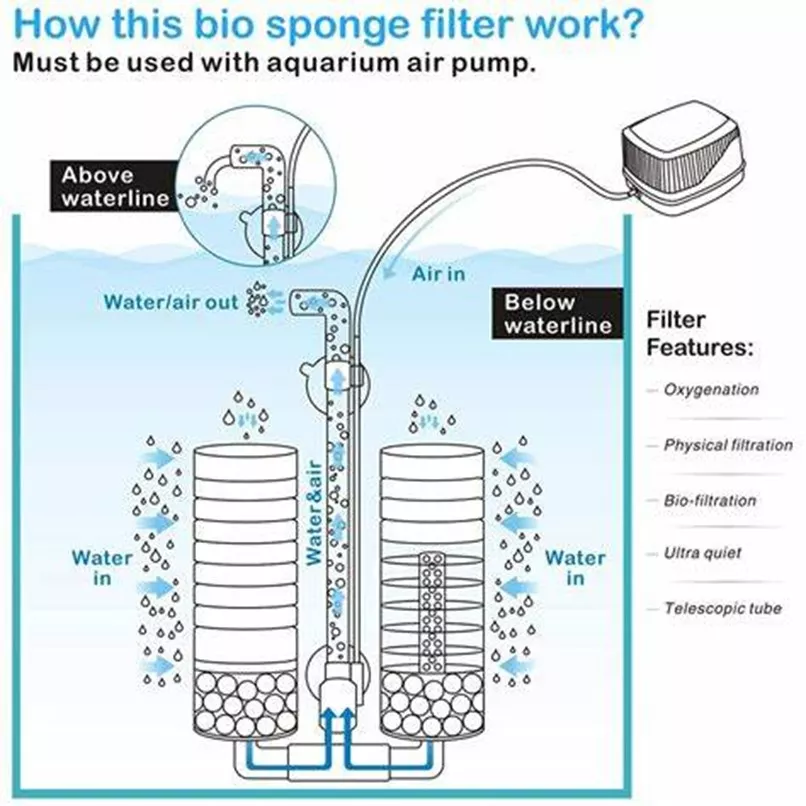
In both cases, an aquarium air pump is used to induce the water flow. That airflow creates bubbles that rise in a vertical tube. That movement helps to pull water through the sponge material and up through the vertical tube. The bubbles also act to oxygenate the water in the tank.
Most aquariums have gravel or sand on the bottom, plants and driftwood mixed in, and, of course, fish. For this SOLIDWORKS Flow Simulation study, I wanted to see what the water flow would look like with water only.
Single-Sponge Filter Results
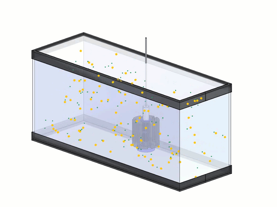
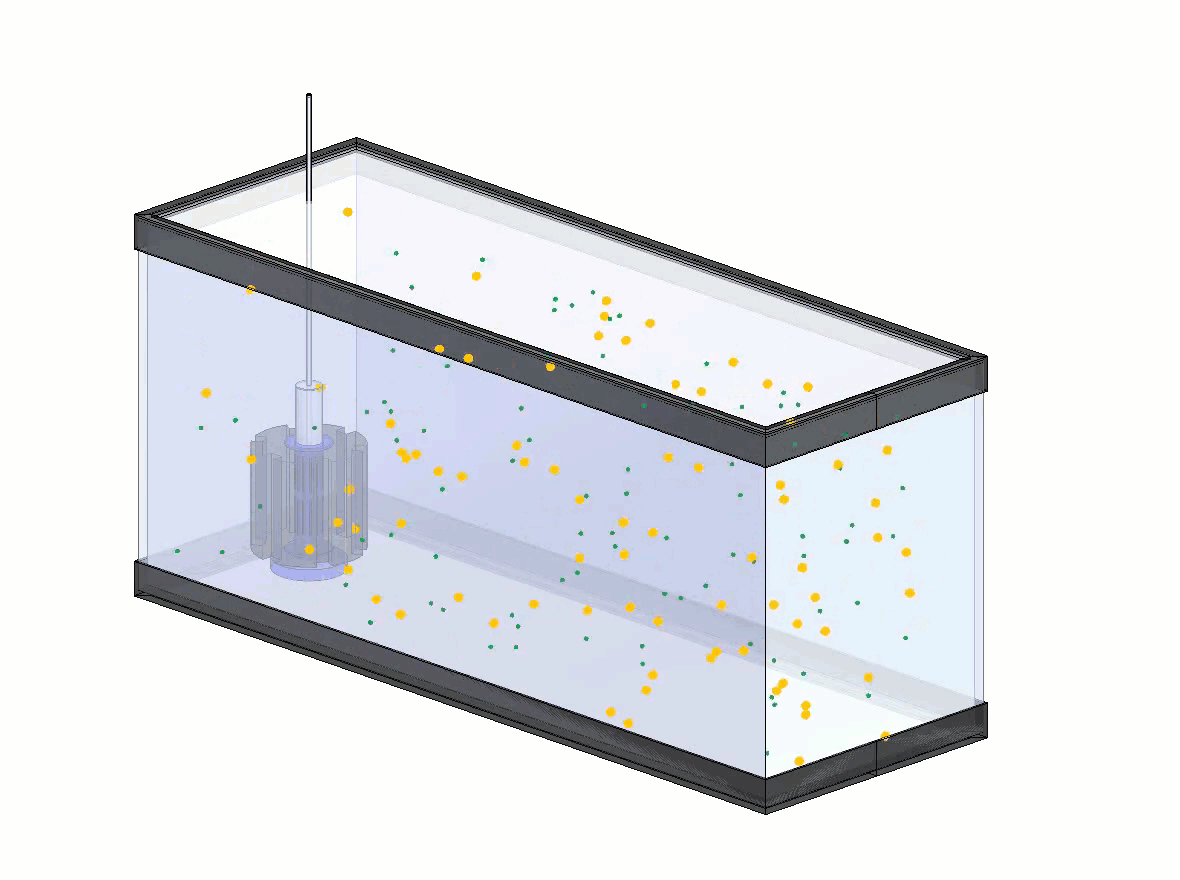
In my first investigation, I used a single-sponge weighted system and tested two positions - one in the middle of the long side and the other in the middle of the short end.
I set up the flow simulation pump flow rate to move the volume of the tank in one hour and got these results:
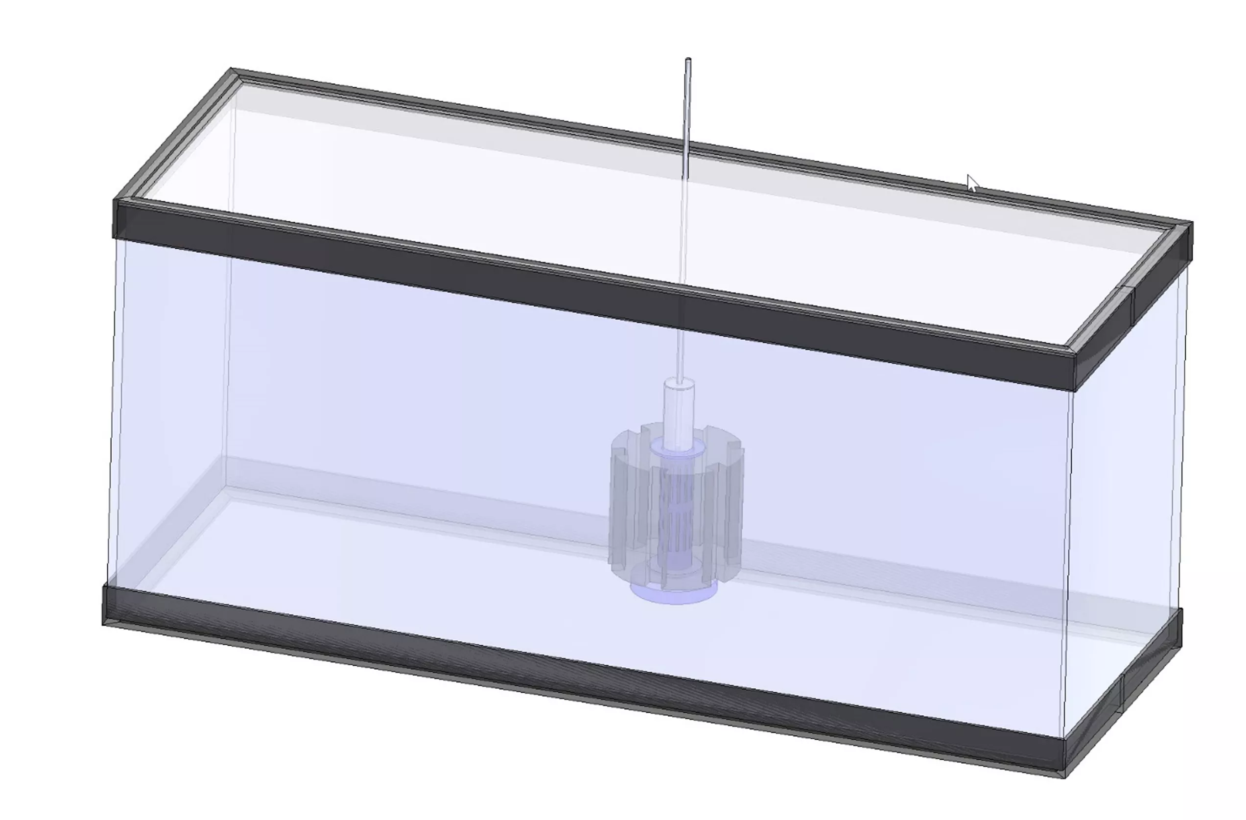
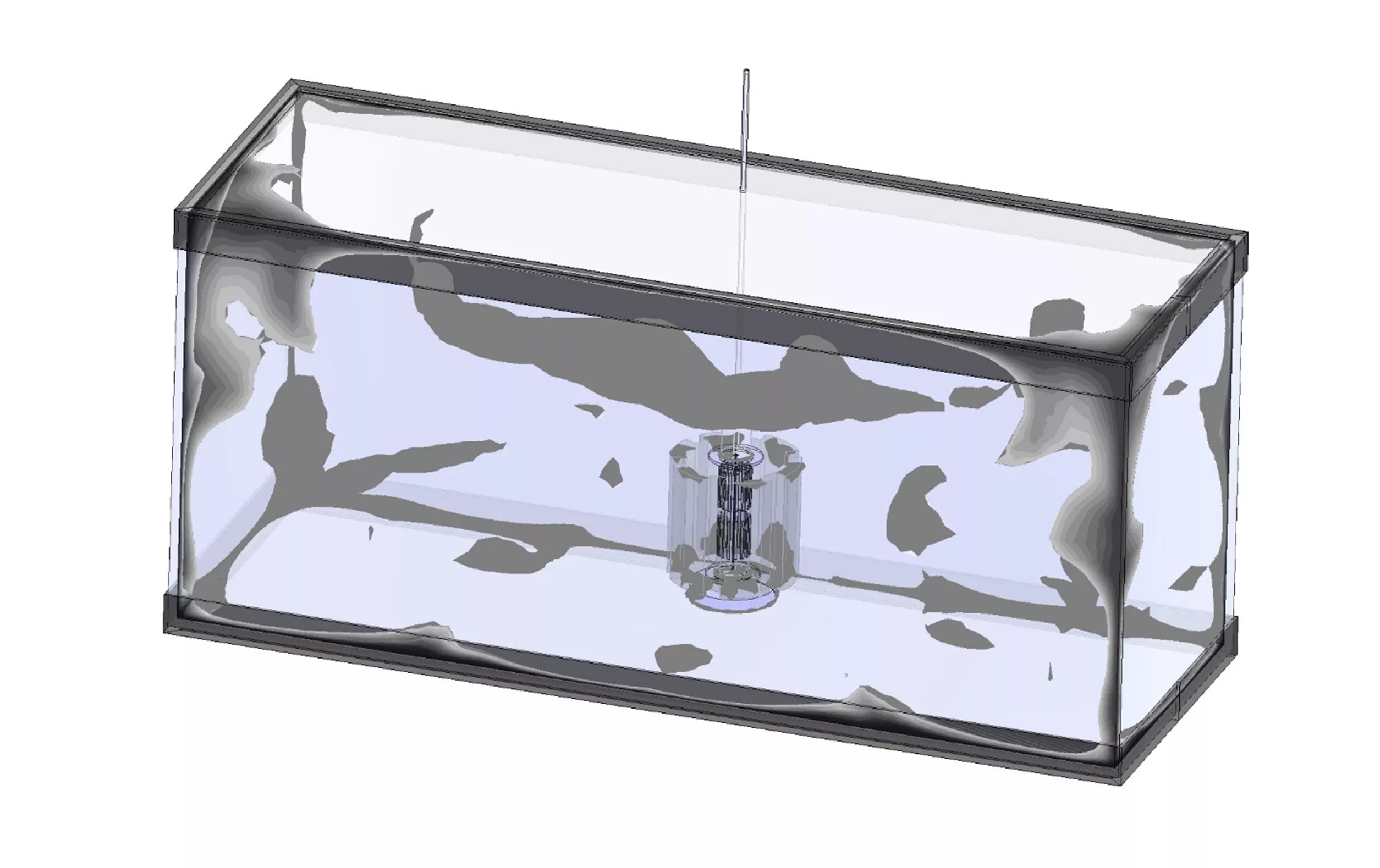
Middle Location - Long Side
Darker areas indicate lower levels of water flow.
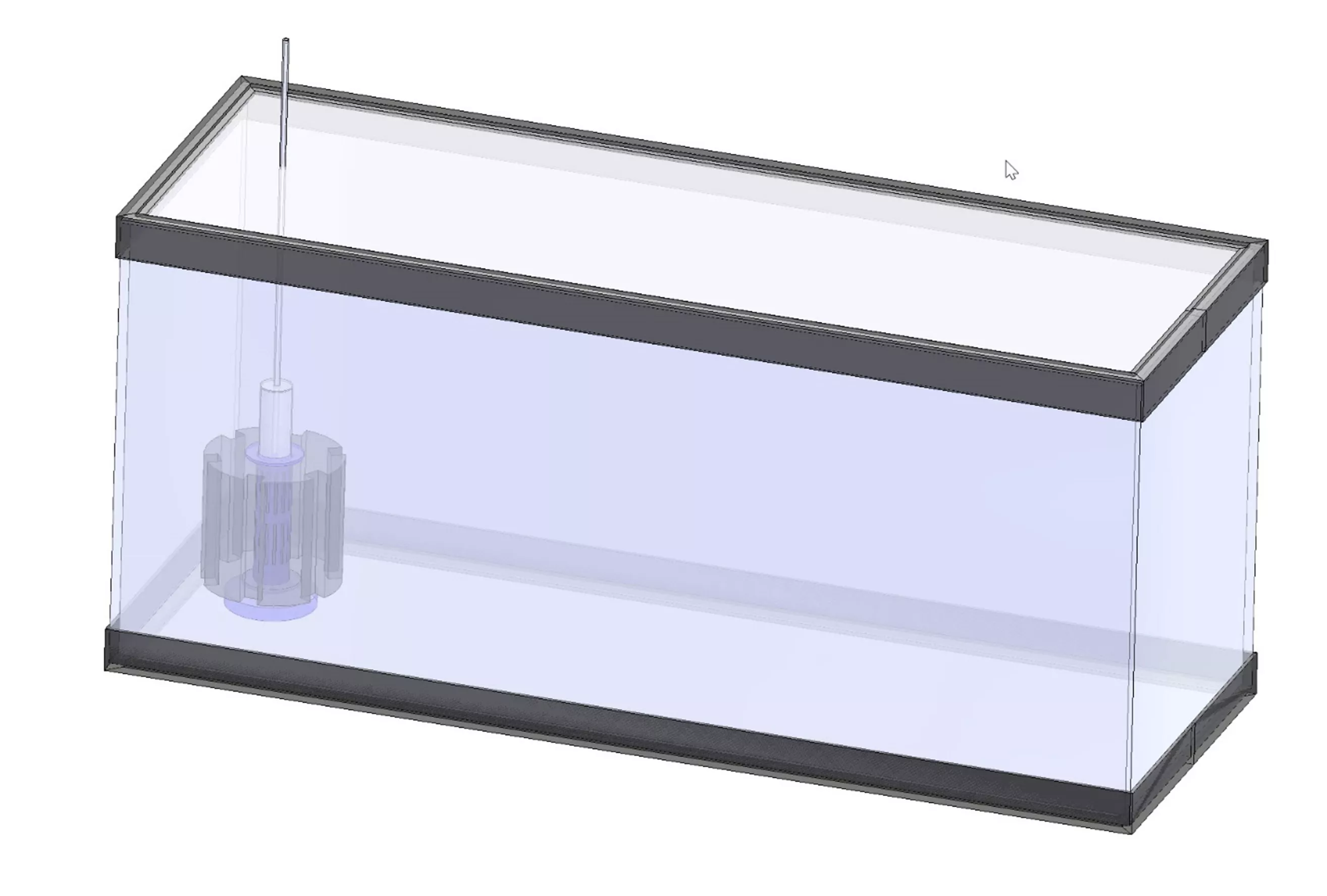
Middle Location - Short Side
Darker areas indicate lower levels of water flow.
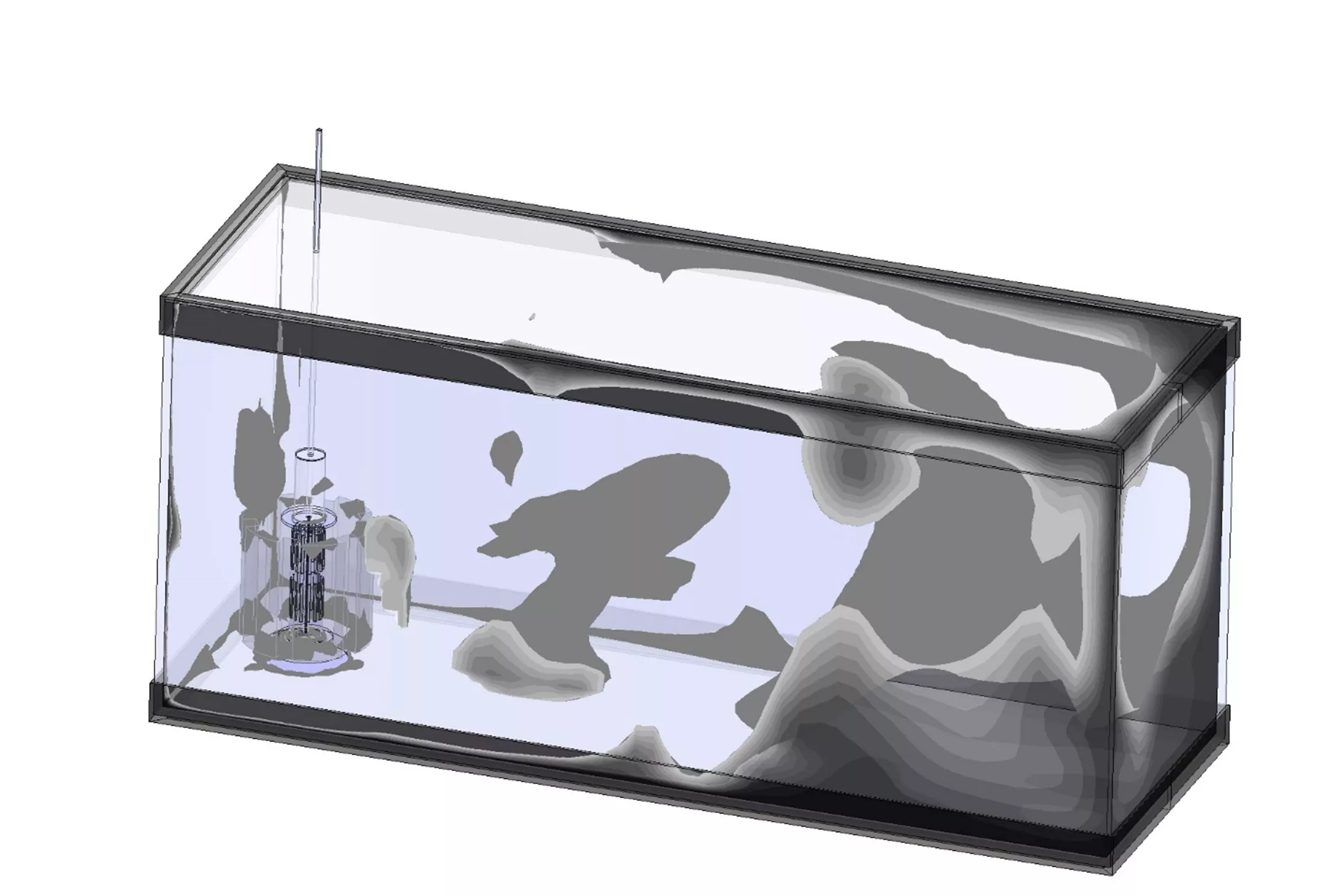
The dead zones, the darker areas, are more prevalent in the side orientation than the middle orientation.
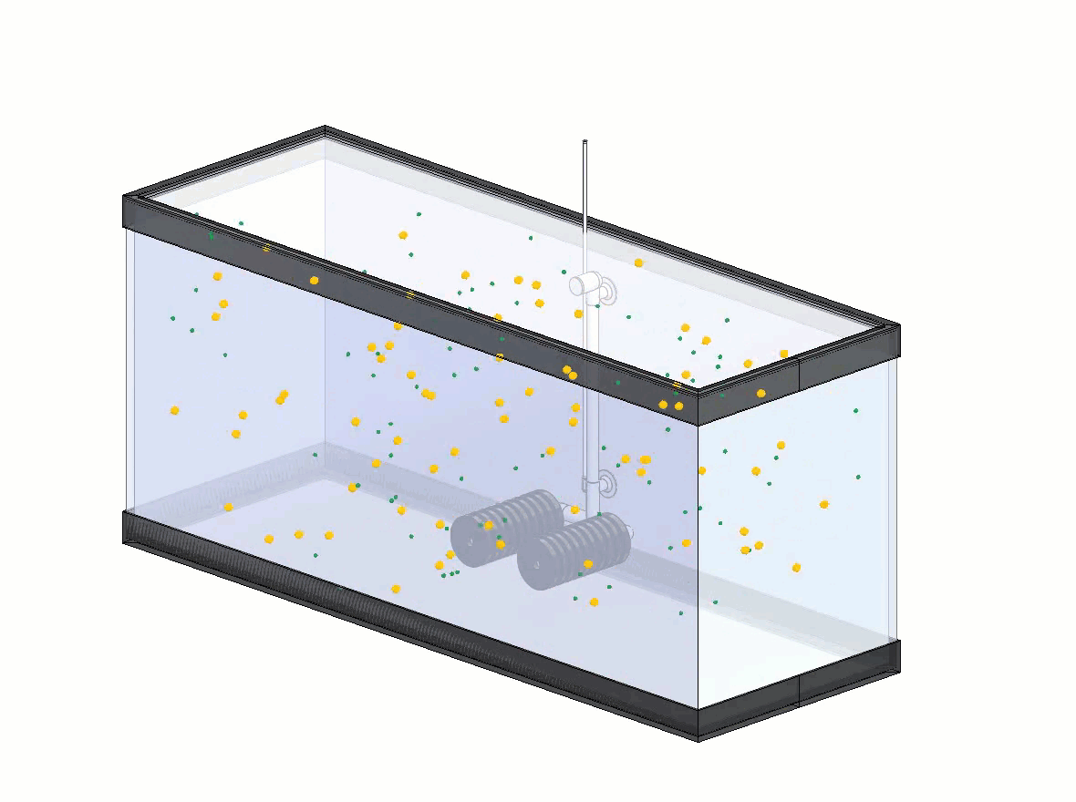
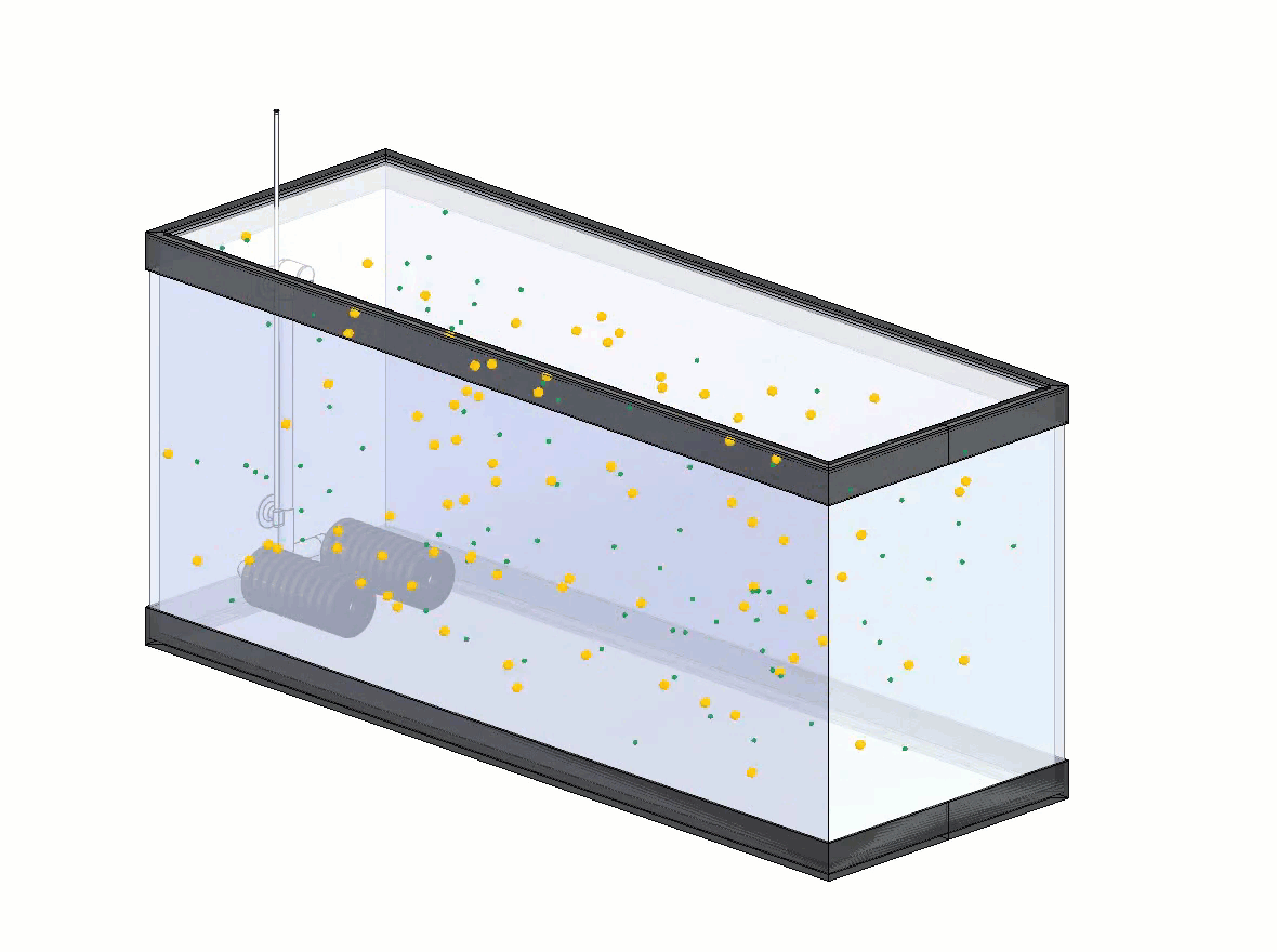
We can also see the differences between the two animated particle studies, which show the distribution of oxygenated water.
Now, let's take a look at a different kind of filter system.
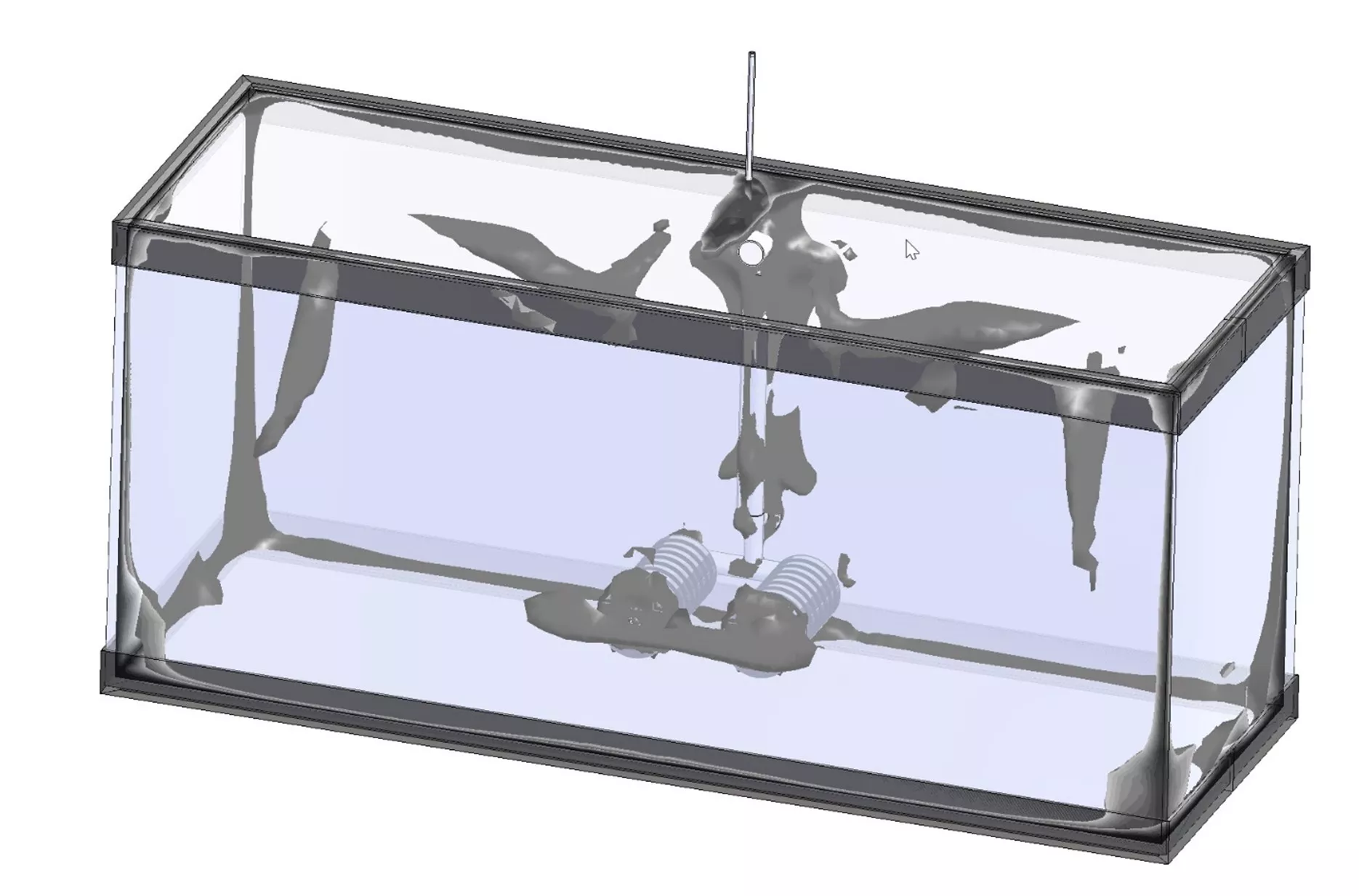
Dual-Sponge Filter Results
Like the single-sponge example, I set the parameters to move the entire volume of the tank in one hour and assumed nothing in the tank but water. After one hour, these are the results for a filter placed in the middle of the long side and in the middle of the short end.
Middle Location - Long Side
Darker areas show lower water flow.
Middle Location - Short Side
The darker areas demonstrate lower water flow.
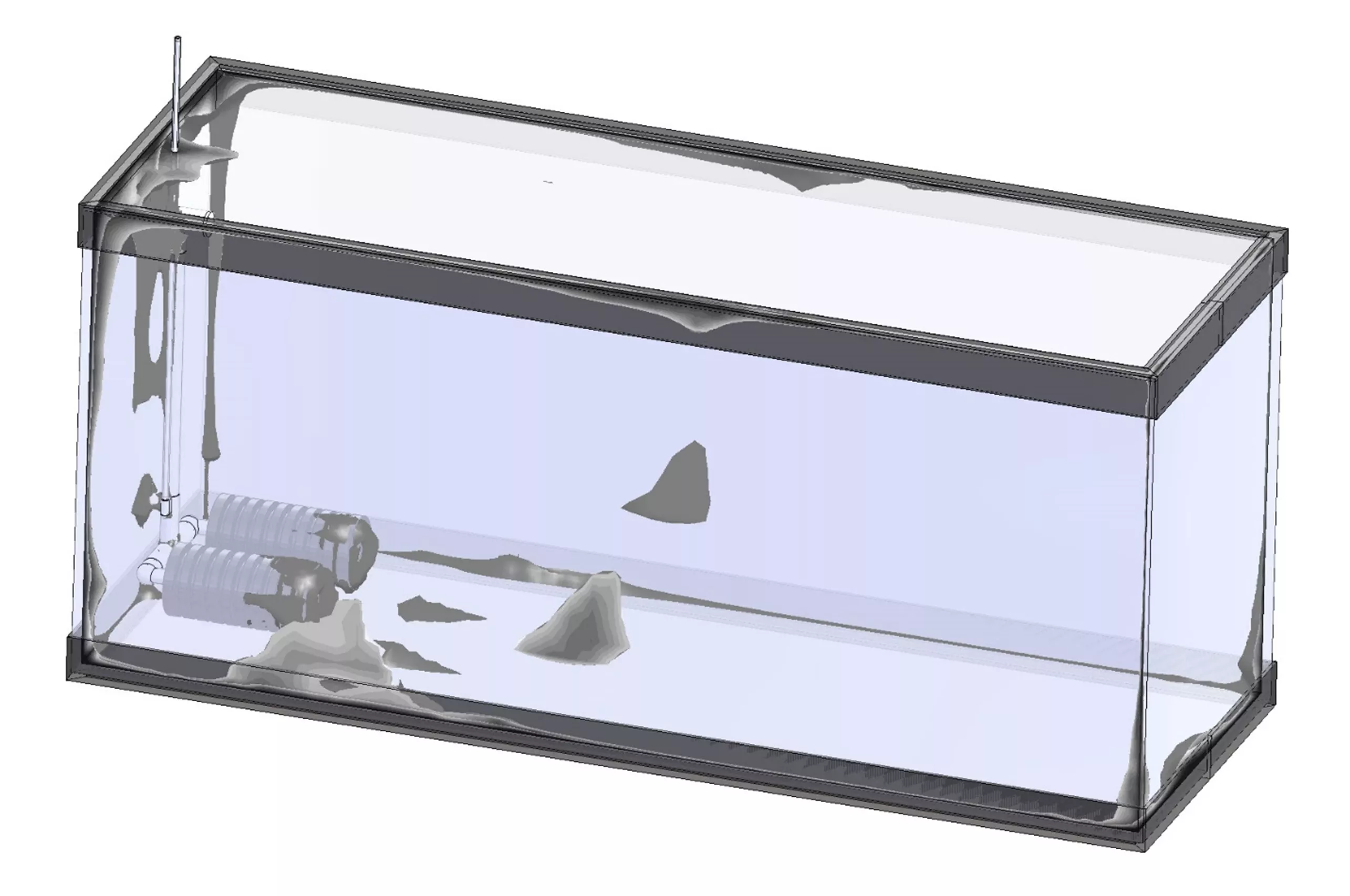
In either location, we can see dead zones (darker areas) on the ends of the sponges and behind the vertical tube. However, the position of the dual-sponge filter does not dramatically affect the dead zone between the two orientations.
We can also see a uniform distribution of oxygenated water in both animated particle studies.
Based on these studies, a dual-filter system has more placement flexibility than a single-sponge weighted system. Although both perform well when positioned in the middle of the aquarium, the dual sponge allows placement at the far end of the aquarium without affecting performance.
Related Articles
Outsmarting Drag Using SOLIDWORKS Flow Simulation
Winter Beehive Analysis Using SOLIDWORKS Flow & Thermal Simulation
SOLIDWORKS Flow Simulation Results Analysis Tools Explained
SOLIDWORKS Flow Simulation Free Surface and Gravity Dependency

About Matthew Kusz
Matthew Kusz is a Senior Technical Support Engineer at GoEngineer. When Matthew isn’t assisting customers with their engineering challenges, he spends his free time repairing antique watches/clocks, designing furniture, tending his aquariums and learning about bee keeping.
Get our wide array of technical resources delivered right to your inbox.
Unsubscribe at any time.