SOLIDWORKS Flow Simulation Free Surface and Gravity Dependency
This article is a companion to this SOLIDWORKS Flow Simulation Tutorial. In it, Free Surfaces are used in combination with time-dependent gravity to simulate water flowing out of a pitcher when rotated 90 degrees. The Transient Explorer is employed in order to view the results of this study, specifically the motion of the water over time.
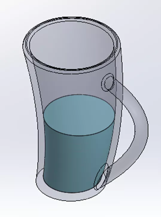
Figure 1: Multibody Part Model of Glass with Water
Gravity Dependency
The direction of gravity is set in the General Settings of a Flow Simulation Project. It is defined in three directions: X, Y, and Z. By default, the X, Y, and Z components of gravity are all constants, but they can instead be controlled by a table or formula. In this case, the option for F(time) -table is used. The Dependency dialogs for the X component and Y component are shown below. These windows can be accessed by selecting the component in General Settings to highlight it and then clicking the Dependency button.

Figure 2: X component Dependency (left) and Y component Dependency (right)
At time 0 s, the gravity is -9.8 m/s^2 in the Y direction and 0 m/s^2 in the X direction. At time 1 s, it is 0 m/s^2 in the Y direction and -9.8 m/s^2 in the X direction. The direction of gravity changing over time has the same effect as the cup rotating 90 degrees in an environment in which gravity is constant. In this way, we can simulate motion like liquid spilling out of a cup without using motion in Simulation.
Transient Explorer
The Transient Explorer is used to animate the results of a time-dependent study in the graphics area. To enable it, check the box for Periodic in the Selected Parameters (Transient Explorer) section of the Saving tab of Calculation Control Options. Select all the parameters for which you want the Transient Explorer to be available. In this case, we eventually want to animate a results Cut Plot of the Volume Fraction of Water, so the Volume Fraction of Water is checked.
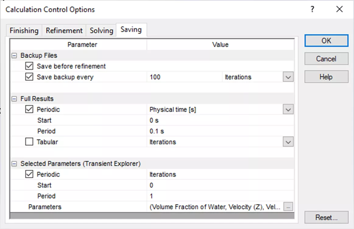
Figure 3: Calculation Control Options with Transient Explorer enabled
Free Surface
What really makes this work is having two immiscible fluids or making this a free surface transient analysis. In General Settings, select both Time Dependent and Free Surface. On the Fluids page, the Default fluid type will be set to Immiscible Mixture, and you will be prompted to select two fluids. In this Project, we are using Air and Water. Set the Initial fluid to Air under Concentrations on the Initial and Ambient Conditions page.
This model has two solid bodies: one is the cup and the other represents the water in the cup. Create a new Initial Condition to set the solid body to be water. This can also be accomplished using a Fluid Subdomain.
Additional Set-up Details and Results
To set up this Project, we'll start by setting the Analysis type to External. Then, check the options for Time Dependent, Gravity, and Free surface. Under Gravity, open up the Dependency dialog for the X component and the Y component and switch both to F(time) - table. The Z component should be 0 m/s^2.
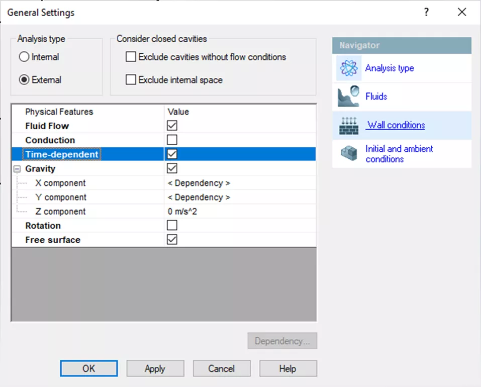
Figure 4: General Settings Analysis type page
For the Default Fluid, select both Air and Water. On the Initial Conditions page, make sure that Air is set to be the Initial fluid under Concentrations.
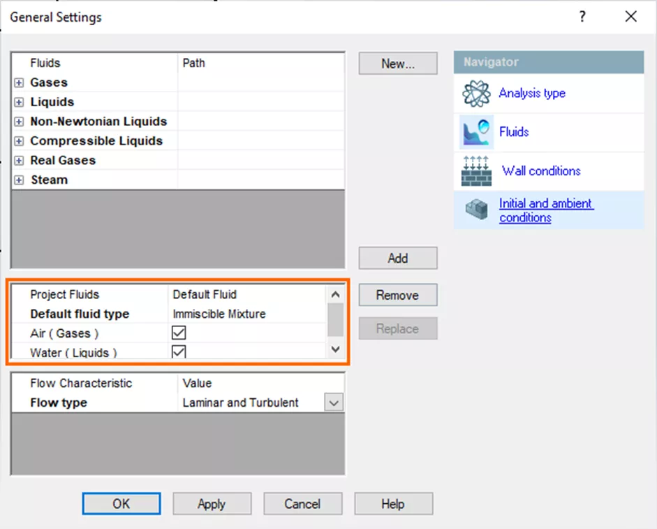
Figure 5: General Settings Fluids page
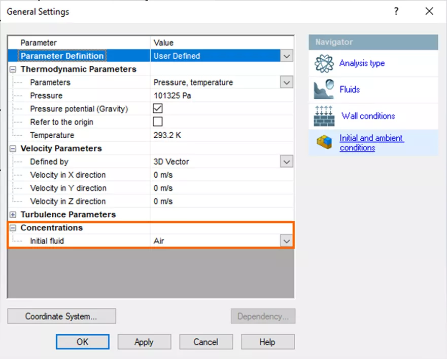
Figure 6: General Settings Initial conditions page
Create a new Initial Condition and select the solid body that represents the water in the cup. Check the box for Disable solid components then choose Water in the Substance Concentrations dropdown below.
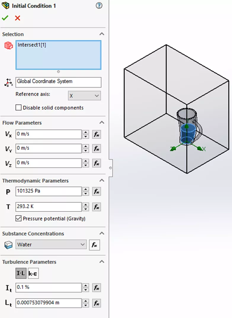
Figure 7: Initial Condition PropertyManager
In Calculation Control Options, the Finish Condition is Physical time and is set to 3 s. This gives the water time to pour out once the cup finishes turning onto its side after 1 s.
In the Saving tab, under Full Results, Periodic is checked and set to Physical time [s]. The Period is 0.1 s. This determines the saved iteration from the start time. Check the box for Periodic under Selected Parameters (Transient Explorer). This enables the Transient Explorer. Click on the "..." button next to Parameters and make sure that all parameters for which you want to use the Transient Explorer are checked. In this case, we want to add Volume Fraction of Water.
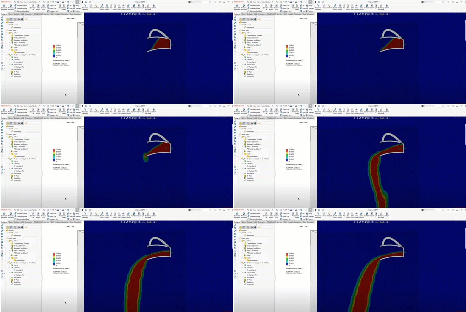
After running a study, create a Cut Plot showing the Volume Fraction of Water. With it visible, right-click on the Results folder and click Transient Explorer. This will cause a Transient Explorer time bar to appear near the bottom of your graphics area. Hide the solid body you set to be water and click the play button to animate the Volume Fraction of Water over time.
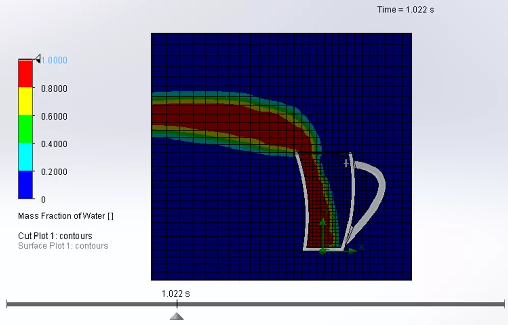
Figure 8: Volume Fraction of Water Cut Plot with Transient Explorer
I hope you found this SOLIDWORKS Flow Simulation tutorial helpful. Check out more below.
Related Articles
SOLIDWORKS Flow Simulation Carbon Monoxide Flow Tracer
SOLIDWORKS Flow Simulation 2024 - What's New
Optimizing Your Workstation Budget for Design & Engineering Applications: Flow Simulation
SOLIDWORKS Flow Simulation Coefficient of Drag

About Lauren McGarry
Lauren McGarry is a Certified SOLIDWORKS Expert based out of San Diego, California. She earned her Bachelor of Science degree from Case Western Reserve University and has been with GoEngineer as a Technical Support Engineer since 2016.
Get our wide array of technical resources delivered right to your inbox.
Unsubscribe at any time.