SOLIDWORKS Sheet Metal Fold and Unfold Tools Explained
In this quick tutorial, we explain how to use some of the sheet metal tools in SOLIDWORKS, specifically the Fold and Unfold tools.
First, let’s set up our base flange, being sure to have a fully defined sketch to start.
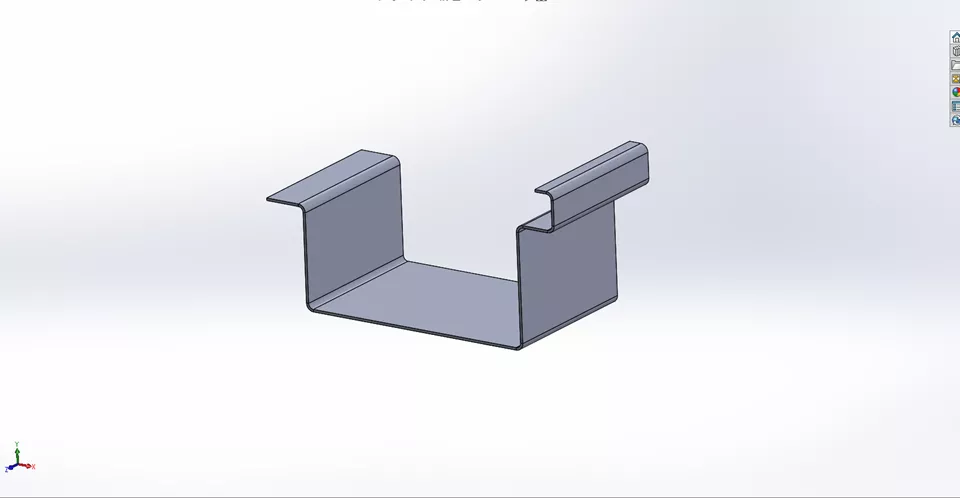
After creating a base flange, find the Fold and Unfold tools in the Sheet Metal tab in the CommandManager. It is often much easier and more efficient to work on sheet metal parts in the flat. These tools will help us to do that.
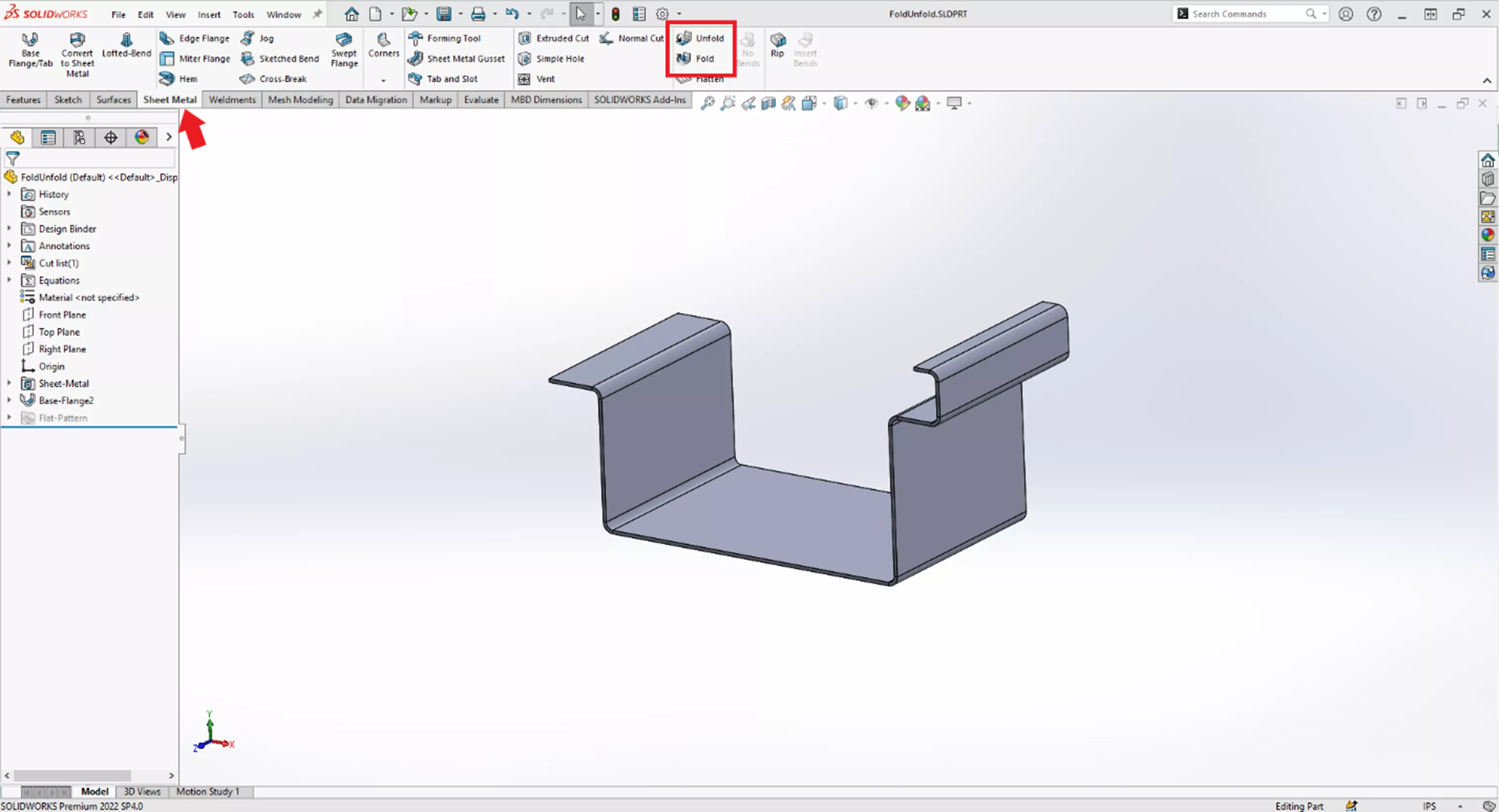
Using the Unfold Tool
Let’s start with the Unfold tool.
SOLIDWORKS will prompt us to choose a Fixed Face. Ensure that the Fixed Face chosen remains constant when using the Fold and Unfold tools. I prefer to use one of the main faces of the base flange.
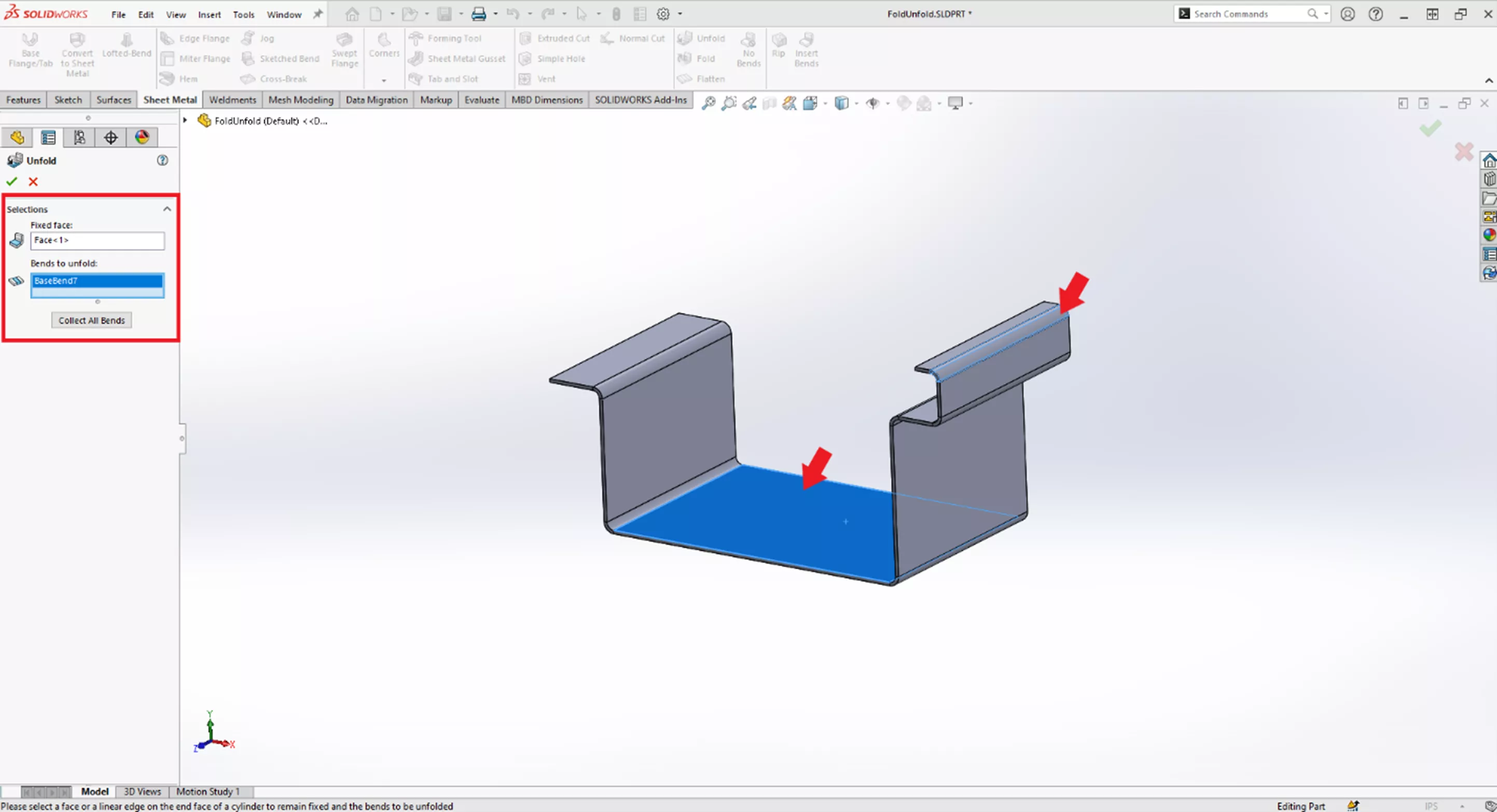
After selecting the Fixed Face, the Unfold tool will need us to choose which bends to unfold.
Choose individual bends or use the Collect All Bends button to select all bends on the flange.
For this example, we will choose an individual bend. Once all desired bends have been selected, click the green check mark to complete the Unfold.
This will put an Unfold in the FeatureManager Design Tree.
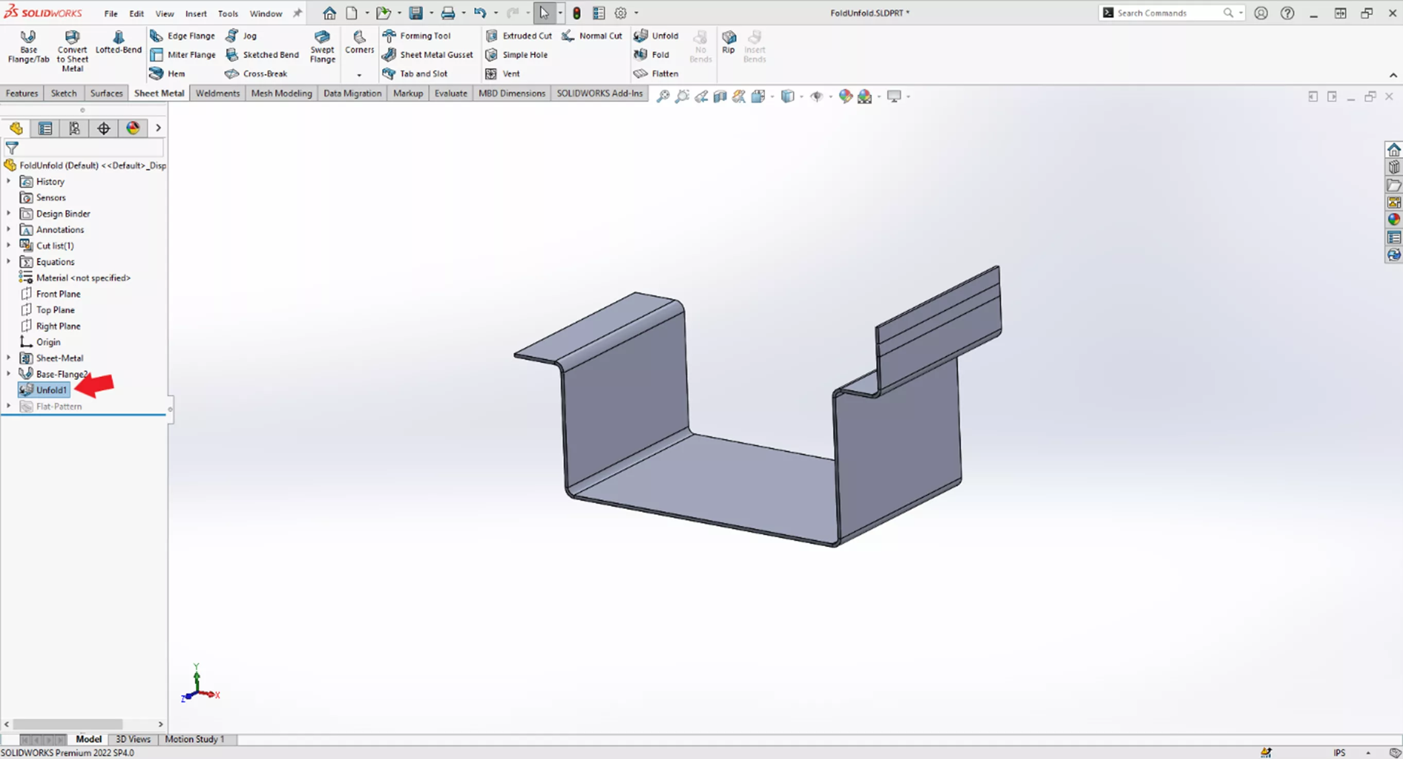
Now that we have Unfolded this bend, we can create a sketch on its surface, sketch a rectangle, and then use Extrude Cut to cut and hole into the base flange.
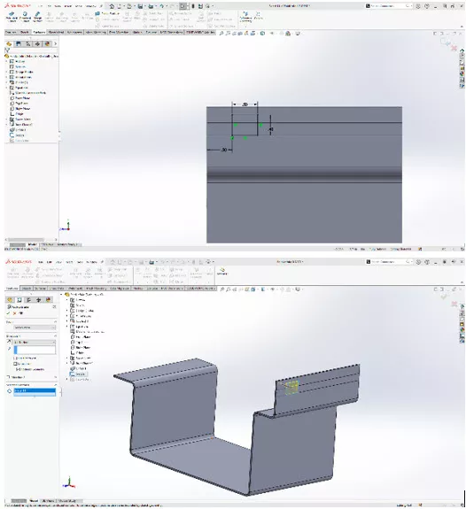
Use the Fold tool to refold the unfolded bend.
Using the Fold Tool
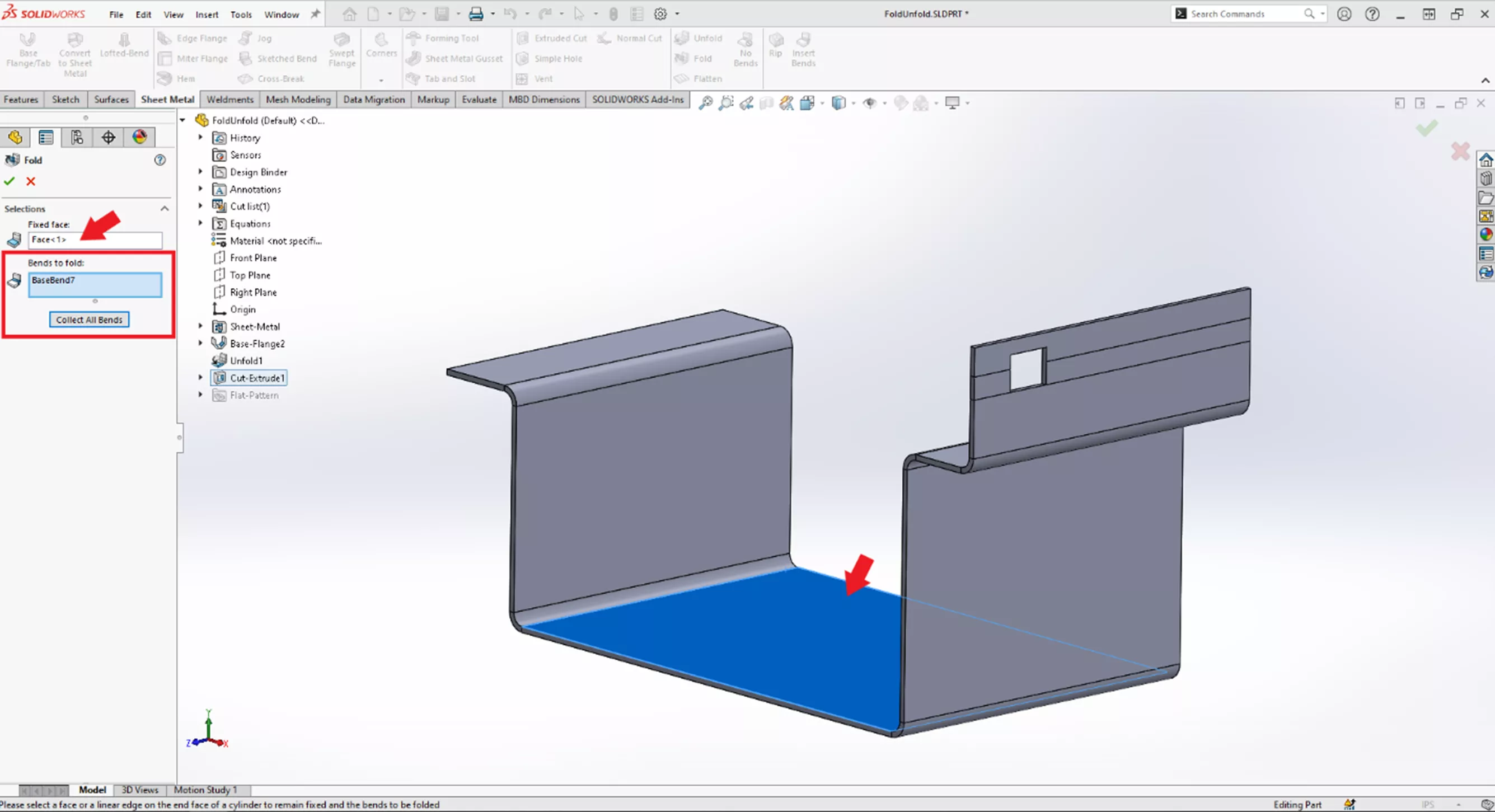
Notice when selecting the Fold tool, it also requires a Fixed Face, but this time, it automatically selects the same Fixed Face from the Unfold previously performed. This helps to keep consistency between the two tools.
In the Fold tool, pick the bends to fold by either manually selecting the individual bends or using the Collect All Bends button.
In the Fold tool, this button selects all bends previously unfolded. By clicking the green check mark, the Fold will be completed.
As you can see, this adds a Fold to our FeatureManager Design Tree, and the cut that we did while the bend was unfolded has now folded with our bend.
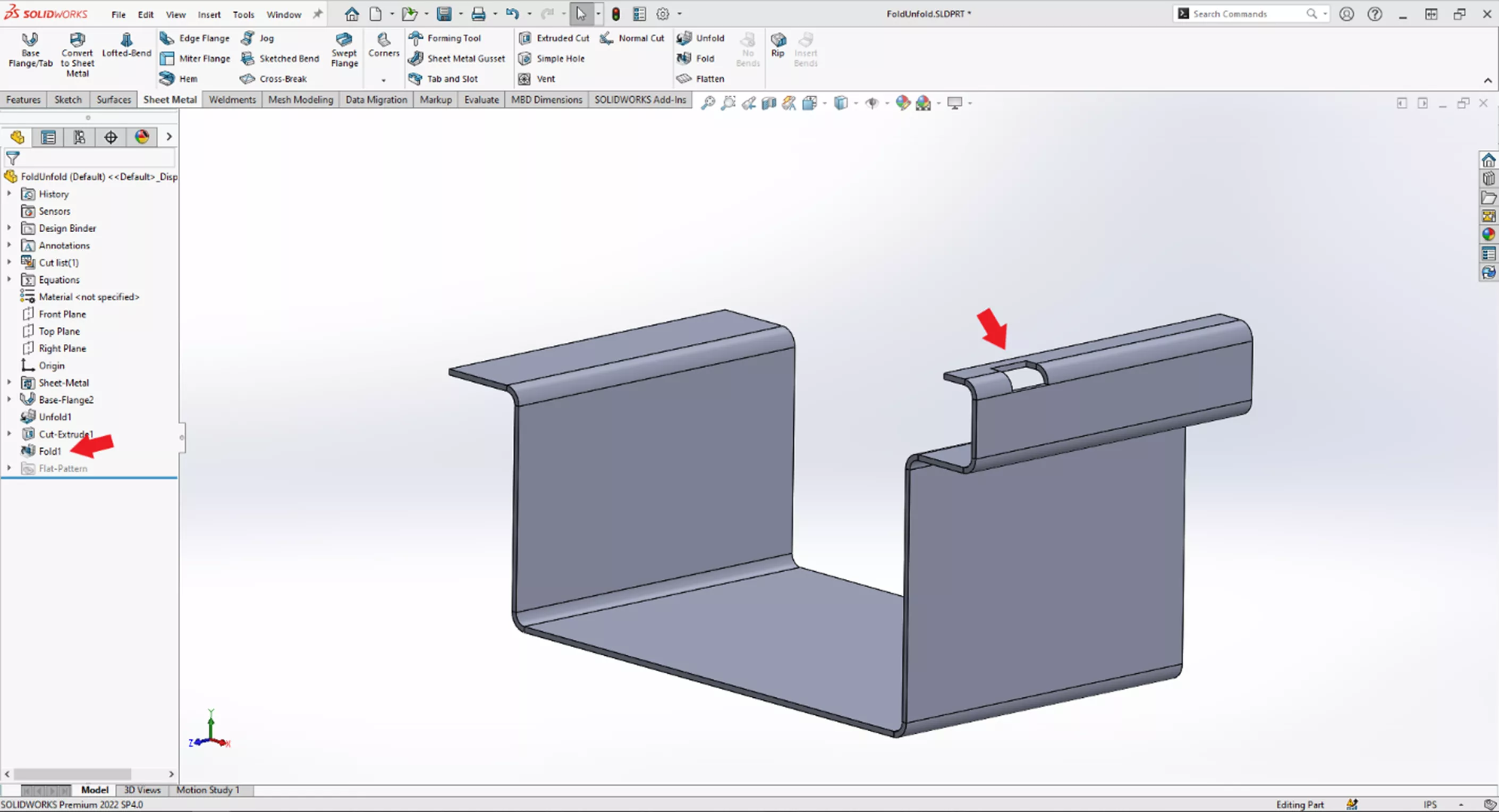
There are other methods for generating this cut after the bend, but by using the Unfold tool to flatten the bend and then generating the cut, we know that the dimensions of the cut are accurate and not distorted by the bend when we generate a flat pattern.
I hope this article helped explain SOLIDWORKS sheet metal fold and unfold tools. Check out more tips and tricks listed below. Additionally, join the GoEngineer Community to participate in the conversation, create forum posts, and answer questions from other SOLIDWORKS users.
Want to take your SOLIDWORKS skills to the next level? Enroll in the official SOLIDWORKS Sheet Metal training course. This course teaches designers how to build standalone sheet metal parts and convert conventional parts to sheet metal in assembly context. Both online and in-person classes are available.

SOLIDWORKS CAD Cheat Sheet
SHORTCUTS ⋅ MOUSE GESTURES ⋅ HOT KEYS
Our SOLIDWORKS CAD Cheat Sheet, featuring over 90 tips and tricks, will help speed up your process.
More SOLIDWORKS Sheet Metal Tutorials
Using Sheet Metal Bodies in SOLIDWORKS Simulation
Show Sheet Metal Bend Lines in a SOLIDWORKS Drawing
SOLIDWORKS: Creating Normal Cuts in Sheet Metal
SOLIDWORKS Convert to Sheet Metal Command Explained
Display SOLIDWORKS Sheet Metal Surface Area in Your Bill of Materials

About GoEngineer
GoEngineer delivers software, technology, and expertise that enable companies to unlock design innovation and deliver better products faster. With more than 40 years of experience and tens of thousands of customers in high tech, medical, machine design, energy and other industries, GoEngineer provides best-in-class design solutions from SOLIDWORKS CAD, Stratasys 3D printing, Creaform & Artec 3D scanning, CAMWorks, PLM, and more
Get our wide array of technical resources delivered right to your inbox.
Unsubscribe at any time.
