SOLIDWORKS Design Checker Tool Explained
Design Checker, available in SOLIDWORKS Professional and SOLIDWORKS Premium, is an add-in that automates the verification of compliance with company or customer standards for drawings. This article provides an overview of the Design Checker tool and how to use it.
- Suggested Article >> Comparing SOLIDWORKS Packages: Features in Standard, Professional, and Premium
SOLIDWORKS Design Checker Activation and Commands
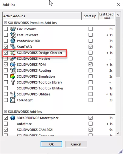
In SOLIDWORKS, Design Checker must first be activated from the Tools > Add-Ins menu.
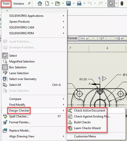
Design Checker commands can then be accessed in the Tools menu, under Design Checker. The four available commands are:
- Check Active Document
- Check Against Existing File...
- Build Checks
- Learn Checks Wizard
The first two commands offer methods for checking documents against the standards which have been created, while the second two commands provide the tools to create those standards.
Standards Creation
The two options for creating the standards against which Design Checker runs are Build Checks and Learn Checks Wizard.
Clicking on Build Checks will launch a Design Checker window (shown below).
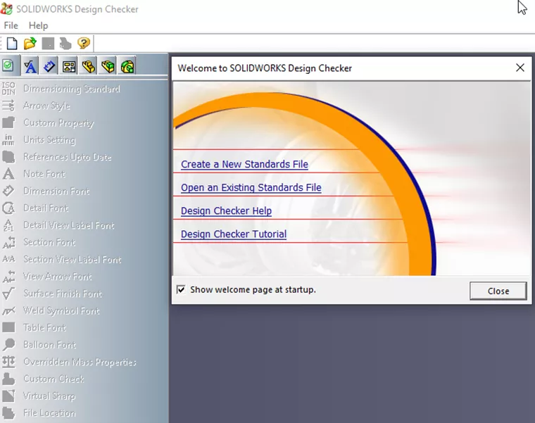
Clicking on Create a New Standards File enables the menus on the left side, from which users can select various aspects of the drawing to control.
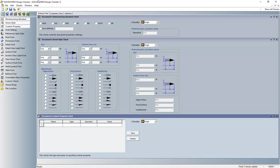
The depth and breadth of what can be controlled in the Design Checker menu can certainly be intimidating. Just keep in mind that not every aspect of your drawings necessarily needs to be controlled in this way. You can also come back and modify an existing standard to add additional controls or remove controls no longer desired.
Once you have a standard file saved and a drawing file open, the tool is ready to be used.
Clicking Check Active Document in the Tools > Design Checker menu opens the Design Checker interface in the Task Pane to the right side of the screen. You should see your saved standard file in the list of available standards. If not, click the green plus symbol and browse for the file.
Put a check in the box for the standards you would like to check the drawing against and click Check Document.
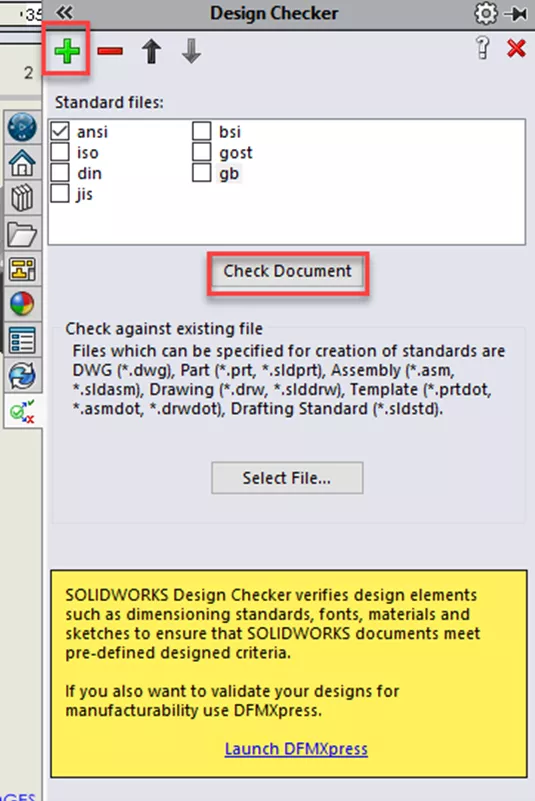
If you haven’t created a standard, but you have a drawing that you know adheres to your desired standards, you can use the Select File… button to use this document as the standard instead. The results are displayed in the Task Pane.
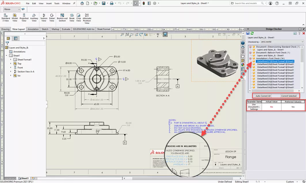
In the results screen, selecting individual line items will highlight the aspect of the drawing which is not in compliance with the standard and provide details regarding the preferred and actual values. Above the details, there are buttons available that allow you to correct only the selected value, or to automatically correct all discrepancies.
![]() Want to learn more? Check out this YouTube video demonstrating these tips, tricks, and best practices.
Want to learn more? Check out this YouTube video demonstrating these tips, tricks, and best practices.
More SOLIDWORKS Tutorials
Inserting Logos Into SOLIDWORKS Parts and Drawings
How to Use Layers in SOLIDWORKS Drawings
SOLIDWORKS 2023 Beta Now Available
Why is My Assembly Invisible in SOLIDWORKS?

About Shaun Johnson
Shaun has been using and supporting SOLIDWORKS since 2000. After spending five years in a support role, he went on to develop products and solutions in industries ranging from consumer electronics to military aviation ground support equipment. Once again in a support role, Shaun enjoys leveraging this experience to help others realize their designs and transform pixels into parts. Whenever he can, Shaun fires up his coal forge and takes a more ‘hands on’ approach to creating parts from raw steel.
Get our wide array of technical resources delivered right to your inbox.
Unsubscribe at any time.