SOLIDWORKS at Home: DIY CAD Projects
I've been a SOLIDWORKS user since 2008 and over time, I have used the software to design many projects around the house. What I enjoy most about SOLIDWORKS is the ability to see a design in its finished state ahead of time and eliminating the trial-and-error process.
Before I started using SOLIDWORKS, I used 2D drafting software for my ideas, which worked well, but definitely had its limitations. I was still 'building' the project in my head as I drew and trimmed my lines in 2D.
In this article, I've compiled some of the projects I've worked on over the years. I can tell that my SOLIDWORKS skills have improved over time as I learned more 'secrets' of the software.
Playhouse/Garden Shed
The playhouse/garden shed is a more recent project. We decided to build a playhouse in our backyard for our kids to enjoy. Instead of going with a kit or a pre-built garden shed to use as a playhouse, I designed one in SOLIDWORKS that could be repurposed as a garden shed when our kids outgrew it. I designed the structure of the playhouse as you would a real house with 2x4 studs and structurally sound openings for windows and a door. What made this process easy in SOLIDWORKS was the weldment tool.
Weldments use sketches to define the framework and profile sketches are used to create the structural members. Your cut list can also be generated to help plan material requirements.
In industry use, weldments often use square or round tubing or different structural profiles. Learn how to create custom weldment profiles in the video below.
For this project, I created dimensional lumber profiles, such as 1”x 2”, 2”x 4”, 2” x 8”, etc. (Keep in mind that true dimensions for lumber are slightly smaller than their listed sizes (i.e., a 2”x4” stud is 1.5”x3.5”).
I had designed the house with a particular overall height in mind, unfortunately, finding a pre-made door that was the desired size was an issue.
I decided to alter my design for a pre-made door that suited my needs which ended up being taller than the original rough opening. SOLIDWORKS gave me the freedom to easily adjust the model to match the new Rough Opening, which then updated my cut list, so I was ready to start building.
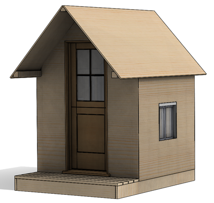
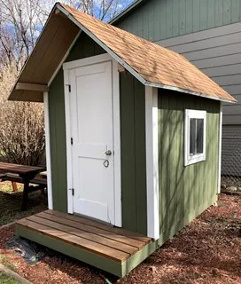
Designed vs built shed
Deck with Raised Flowerbeds
This was a two-part project, as I designed and built the deck years before the flowerbeds. The deck was designed as an assembly, using individual part files brought together with mates and patterns. For the flowerbeds, I utilized weldments and the mirror command in the assembly to create the ‘opposite hand’ version (shortening design time and eliminating errors in my cut list). In this project, I used the existing assembly of the deck to see how the finished flowerbeds would look before cutting a single board.
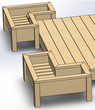
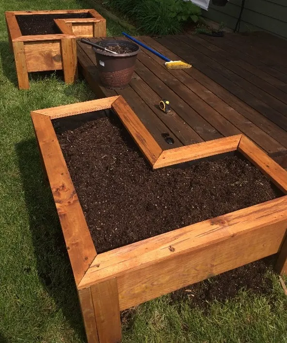
Designed vs finished and installed
DVD/Bookshelf
This is one of my earliest projects listed in this article. The end of the hallway in my basement has a ‘nook’ which is about the depth of a DVD/Blu-ray case. The key considerations for this project were the height and depth of the nook in the hallway. I wanted to make the shelving unit as large as possible, but not extend from the wall into the hallway since there were doors to two rooms on either side of the hallway and the shelves could not interfere with entry into the rooms.
I designed the unit almost exactly as tall as the space (floor to ceiling). Before I started fabricating, I discovered that the ‘tip-in’ height of the unit needed to be less than the ceiling height (see below). I found a formula for calculating the ‘minimum ceiling height’ = √(Height^2 x Depth^2). I adjusted the height of the model to shrink the overall height to allow for the minimum ceiling height. If I had built the unit to match my drawing and cut list, I would have wasted material and time fixing my mistake.
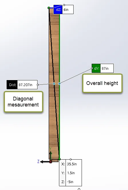
Using the Measure tool in SOLIDWORKS, I ensured that as I tipped the finished unit in place, the unit doesn’t interfere with the ceiling or floor.
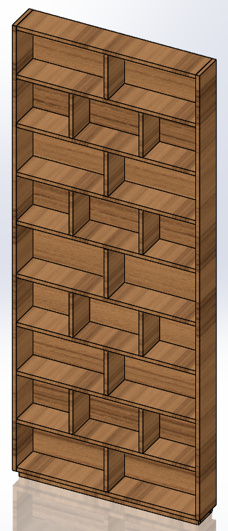
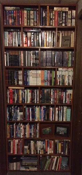
A designed vs finished shelving unit
PVC Pipe Drum
This design was fun to build. My wife and I had attended a performance of The Blue Man Group. If you are unfamiliar with the group, they are well known for their large, intricate PVC pipe drums. After the performance, my wife (who is a middle school band director) asked me if I could make a version of the PVC pipe drum for her students.
Over the years, the finished product has been used at several concerts at schools all over the city. It was last used at our daughter’s 8th Grade Ensembles concert last spring. As you can see, it has been decorated by the students since it was first assembled.
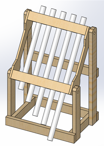
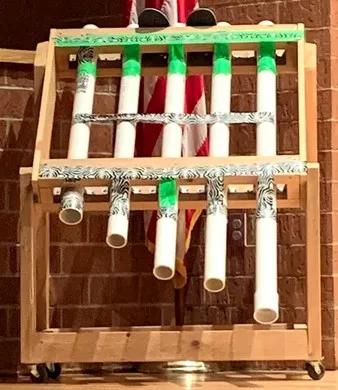
Left: PVC pipe drum designed in 2012 Left: Drum still in use at a concert in 2020
Lathe Stand
In 2019 I received a lathe for Christmas and needed to design a stand for it in my garage. The height of the stand is important for ergonomics as the center of the spindle (and your workpiece) must be around the same height as your elbow. I found a 3D model of a lathe that matched the specs of my lathe on GrabCAD (thanks, Andrew Barney!). I used the model as a guide to determine my overall dimensions and cut list.
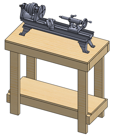
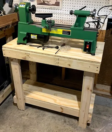
Lathe stand as-designed vs finished product
Vertical Chess Board
My latest project idea, designed in SOLIDWORKS, has not been built yet . I recently saw a ‘vertical chess board’ at a local craft show to be hung on the wall, moving the pieces from shelf to shelf. My wife and I agreed it would be something fun to have in our home. Rather than model the individual pieces to make sure they fit, I turned to 3D Content Central .
3D Content Central is an online library of models from suppliers and users with SOLIDWORKS files available to download for free. I found a very detailed set of chess pieces created and uploaded by Michael Lord to speed up the design process. Thanks, Michael!
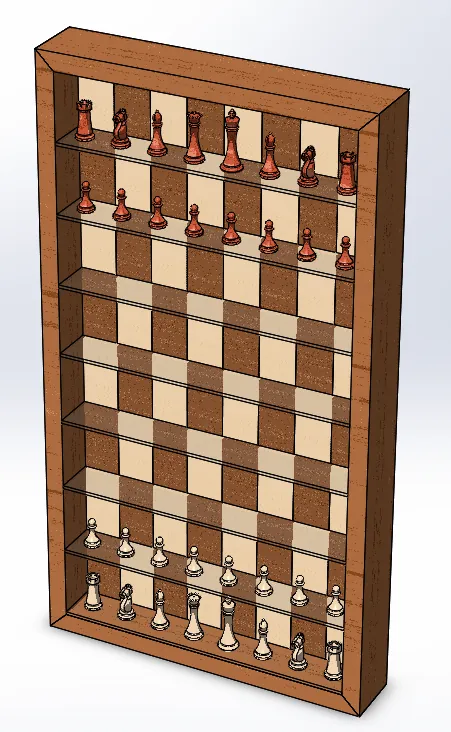
Preliminary design of the vertical chess board
As you can tell, I really enjoy talking about and using SOLIDWORKS. It is a valuable design tool that helps bring your ideas to reality. Design validation tools within the software help you solve challenges before production, and the library files in 3D Content Central are available to help validate your design.
Check Out More SOLIDWORKS Design Hacks
Wonder Woman Costume Comes to Life with 3D Printing, 3D Scanning, and 3D Design
Artichoke Lamp Shade Modification: Design Hacks
Creating a 3D Printed Race Medallion Hanger Using SOLIDWORKS

About Brad Hakeman
Bradley Hakeman is an Application Engineer at GoEngineer. When he isn’t helping customers with their SOLIDWORKS related challenges, he is keeping up on the latest features of SOLIDWORKS. In his spare time, he’s trying to sort out his kids’ soccer schedules and working on household projects, many of which were designed in SOLIDWORKS. Most recently, he has taken up woodturning, currently focusing on pen making.
Get our wide array of technical resources delivered right to your inbox.
Unsubscribe at any time.