Optimizing Golf Design Using SOLIDWORKS Tools
When given the incredible opportunity to present at 3DEXPERIENCE World 2020 , we shared how we used SOLIDWORKS to design golf equipment, how simulation can validate design theories, and AI or Topology Optimization could change the way golf putters look.
We decided to focus on a blade style putter design hitting a ten-foot putt. Why ten feet? Statistically, the average golfer will have 8 putts from the 9-11 to foot window in a round of golf. So, let’s say you shoot 90 and you want to shoot lower scores. You make all eight of the putts mentioned and your score drops from 90 to 82. The other thing we factored in is that as the putt length decreased, that golfers tried to hold the face of the putter square to the target line of the putt.
There are several long standing theories regarding putter designs, especially the hosel position; you have the face balanced or heel-ward.
The face balanced position is where the centerline of the shaft goes through the center of the head (heel to toe). This position is for golfers making a square-square stroke, the face of the putter is being held as square to the target as much as possible minimizing the face rotation of the putter.
The second hosel position is where the hosel is shifted heel-ward. This moves the centerline of the shaft heel-ward of the center of the head. Typically, this type of head is reserved for a putter face that rotates open on the back stroke, square at impact and closed post impact.
Our goal was to validate these theories and ask the question, “is there a better location of the hosel that helps golfers make more putts?” We focused on the ten-foot putt with a blade putter, a square-square stroke path and what we found along the way was something amazing.
Alignment: Templates with global variables
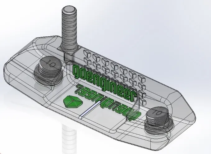
To make it easy for us to quickly make a model we started by creating templates that had our desired face profile global variables to define the critical dimensions.
To create our template, we opened a standard part file: Part_IN that comes with every version of SOLIDWORKS. We then created sketches where we assigned each dimension a global variable (Figure 1).
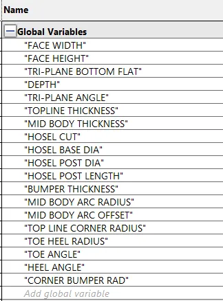
Figure 1 – Global variable naming
We then saved the file as a part template with a name we could easily recall using the File > Save As Command and changed the Save as Type to: Part Templates (*.prtdot). We can preview the template by single left clicking on the template name and get a preview of the template with sketches ready for features (Figure 2). To learn how to create part templates and global variables please watch this video.
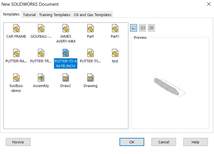
Figure 2 – Templates and template preview
Path: Sketch contours
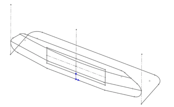
Figure 3 – Sketch contours within a template
If you have taken the Advanced Modeling class, we talk early on about using multiple sketches within a sketch and using sketch contours to create features. What we learned over the years was the quickest way to create a blade style putter was to use sketch contours. Simply select the sketch and activate the feature desired. See Figure 3 for the sketch contours used for this model. To learn how to use sketch contours, please watch our video
Speed: Configurations
In order to create the model for evaluation we needed multiple configurations of the putter. We placed the hosel in three positions, 0.892”, 1.071”, and 1.250” from the center line of the putter. 0.892” and 1.250” are the traditional positions we mentioned earlier, we created a position 1.071” that put the outside diameter of the shaft that goes over the hosel tangent to the outside diameter of the ball. See Figure 4 below for hosel locations and how it affects the CG.
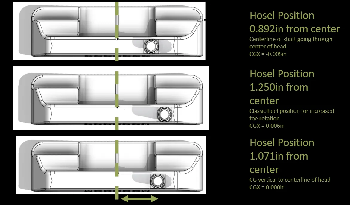
Figure 4 – Hosel configurations and CG locations
Score: How simulation validates design theories
Given the three possible putter head designs we asked, “what is the usual way putters are physically tested and compared?” The answer is simple – long putts on a hard, flat surface. Thus, the inertial effects between the putter and the ball drove the motion.
This told us that kinematic motion analysis, or SOLIDWORKS Motion Analysis, was the best Simulation tool to use. With it we asked, “what putter head design produces the least angular displacement of the golf ball after 10 feet, especially if the golf ball is hit off-center?”
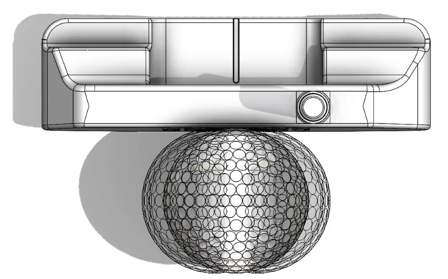
Figure 5 – Three ball positions tested – 0.25in shift toe and heel-ward
In SOLIDWORKS Motion Analysis, we controlled the motion of the putter using mates and motors. We swung the putter head back two inches over 0.4 seconds, then hit the ball at 5mph.
As the putter struck the ball, Solid Body Contact allowed the two components to collide and energy to be transferred. We used a restitution coefficient of one between the putter and the golf ball, meaning no energy was lost.
The loft of the club caused the ball to pop into the air. As it moved towards the ground, it needed another Solid Body Contact between the golf ball and the ground. To represent the ball rolling on grass, we used a restitution coefficient of 0.2.
The ball rolled ten feet horizontally to pass the plane of the cup. We then measured the angular deviation from that ending position to the center of the cup.
We then ran this study for the three putter designs and three ball positions, totaling nine data points. If you’d like to learn how to use Motion Analysis, please watch this video
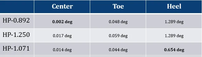
Table 1 – Angular Displacement results for three putter designs and three ball positions
When hitting the ball dead-center the classical design, 0.892, produces the least deflection. However, all three designs do not have enough deflection to miss the 4.25in diameter cup after ten feet.
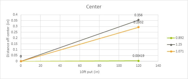
Table 2 – Distance off-center when ball offset 0in
The largest deflections happen at the heel-ward shift of the golf ball, calculating those distances over ten feet gives us Table 3.
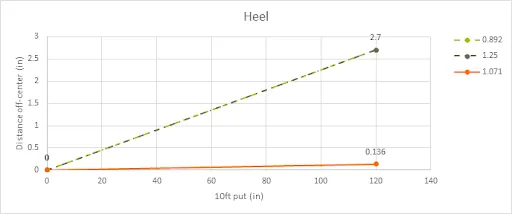
Table 3 – Distance off-center when ball at 0.25in heel-ward
From Table 3 we see that both classic designs produce a large enough deflection to miss the cup, while the new design still sinks the putt!
The results for this third design are compelling. In fact, they are so compelling that we should manufacture the club and move on to physical testing!
Holed it: How we can use Topology Optimization for golf
Motion Analysis helped us find a design that we normally would have avoided, and so far it’s got great responses in physical testing. What else could simulation tell us about putter design? Could it help us find more designs of the future?
Using Topology Optimization, we create organic shapes that still hold design requirements like maximum stiffness, symmetricality, and exact weight specifications. In this case, we started with a blocky design and provided the following requirements:
- Forces: Gravity, 1lbf on the clubface, 10g weights on each post.
- Restraints: Hozzle port fixed, symmetrical
- Goals: Reduce mass until 380g, first natural frequency above 1000Hz.
With the applied forces we represent the club striking the ball, and the necessary inertia for stability. With restraints we aim to keep CG in the center of the putter head. With goals we hit tour weight requirements, and attempt to damp out vibrations by keeping natural frequencies high.
After running the analysis, SOLIDWORKS produced the shape seen in Figure 6. If you’d like to learn how to use Topology Optimization, please watch this video.
Figure 6 – Topology Optimization results
Using simulation functions, we can export the shape and clean it up into a smooth geometry (Figure 7).
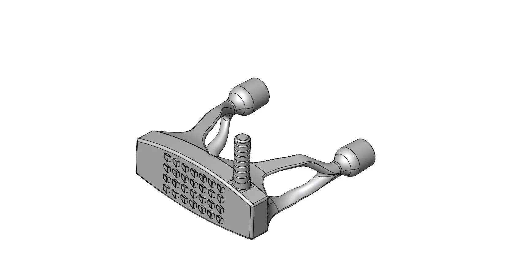
Figure 7 – Modeled version of Topology Optimized shape
Interesting! Let’s compare that against other putter designs on tour. Our optimized shape is like the putter design in the top left – the design that just won the Shell Houston Open. And our blade putter design is similar to the putter on the bottom right – a consistent favorite that has won multiple tournaments.
Want to do great things using SOLIDWORKS CAD? Contact us.

About David Cersley
David has been using SOLIDWORKS since 2005 across multiple industries most notably Golf Club Design. He owned and operated a successful design and consulting company that used SOLIDWORKS to bring napkin sketches to production. The industries he's been a part of range from Medical, Aquaponics, Forging, CNC Shops, Roto-Molding factories. He is a proud father to daughter Emmaline (8) and is a husband of 19 years. He is a two-time Ironman finisher and recently qualified for the Boston Marathon.
Get our wide array of technical resources delivered right to your inbox.
Unsubscribe at any time.