Easy Ways to Model a Wye Pipe in SOLIDWORKS
In this tutorial, we'll take a look at a few of the possible ways to model a Wye Pipe in SOLIDWORKS.
Wye pipes exist in various materials, from formed plastic to welded metal. In SOLIDWORKS however, the question of how to model the initial shape can be a lot more complicated.
Revolve
One possible way is to make three revolves. (Figure 1)
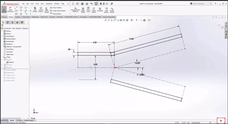
Figure 1. Three revolves
You can see the three profiles and center lines that each one is revolved around. Doing it this way, however, can result in unwanted cuts and offsets within the model. (Figure 2)
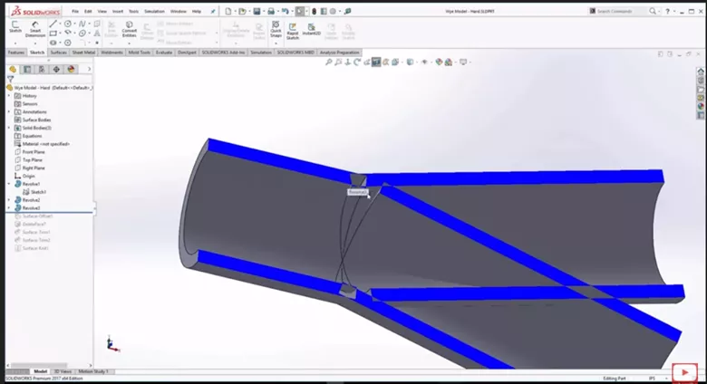
Figure 2. Weird cuts and offsets
This can be fixed by using surface offsets and trims to make this a SOLIDWORKS pipe, but that too can get messy.
So how can we get the same results using revolves without having to make all of those cuts and surfaces?
We can modify the revolves to give us three solid pipes that we can then merge together and use the Shell command.
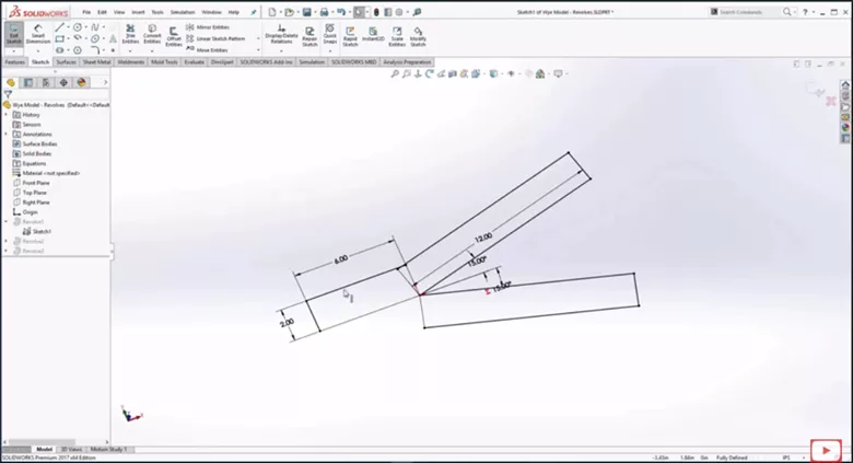
Figure 3. Solid pipe revolve sketch
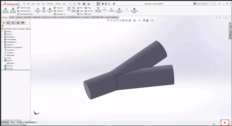
Figure 4. Solid Pipe
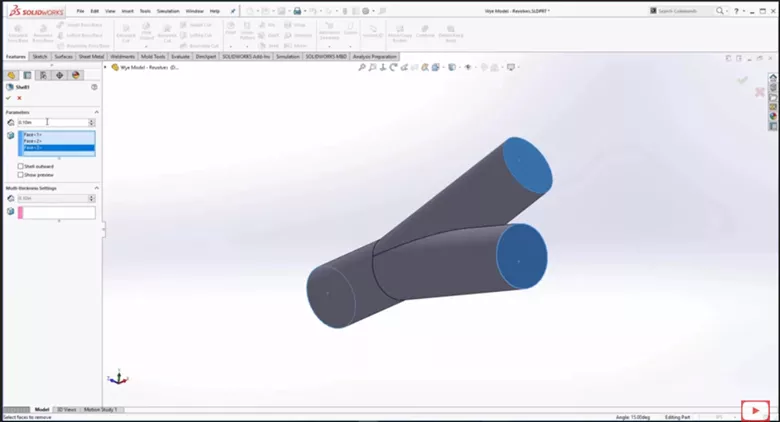
Figure 5. Shell Revolve
This works and is pretty easy to do, but with the revolves we are still creating many separate features.
An even easier way to do this is with Sweeps.
Sweep
With Sweeps, we can use an even simpler sketch. We can have one sketch following the path of part of the pipe, and another for the offshoot.
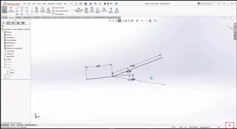
Figure 6. Sweep Sketch
We can then create a circular sketch on a work plane.
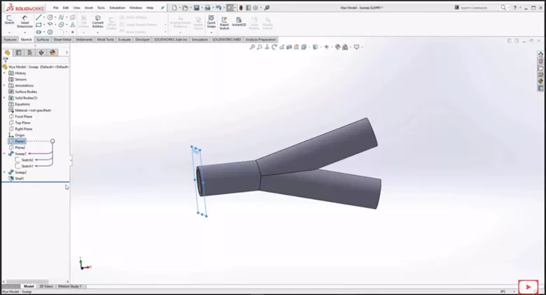
Figure 7. Circular Sketch on work plane
Then sweep along the paths we created.
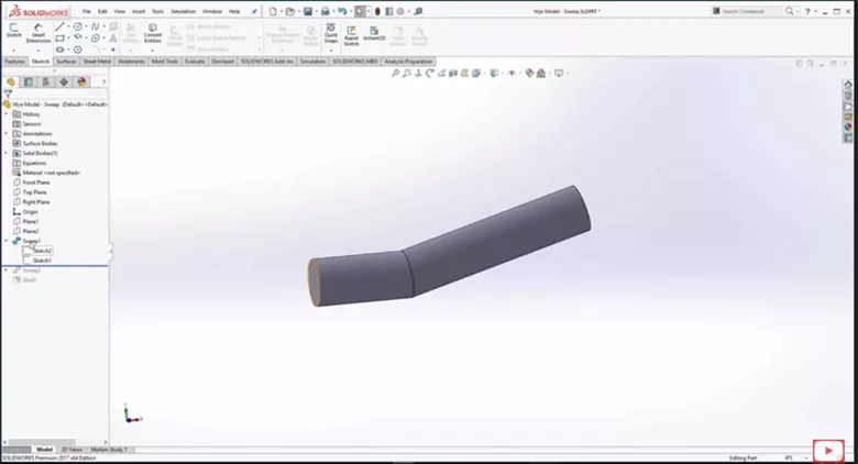
Figure 8. First path
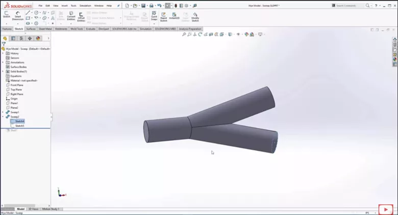
Figure 9. Secondary Sweep
Once the two paths have been swept, we can use the Shell tool to obtain our desired pipe.
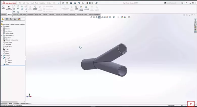
Figure 10. Shelled Pipe
This process was made even easier back in 2017 as the option to sweep using a circular profile was implemented and is still in use today.
Changing Inlet/Outlet size
After completing the design for the wye pipe, suppose we wanted the diameter of the inlet to be smaller than the diameter of the outlet.
One possible way to do this is to modify one of the sweeps that we had previously created to be a different diameter. You can see below that we went in and on the branch of our wye pipe changed the diameter of the second sweep to be less than the first sweep.
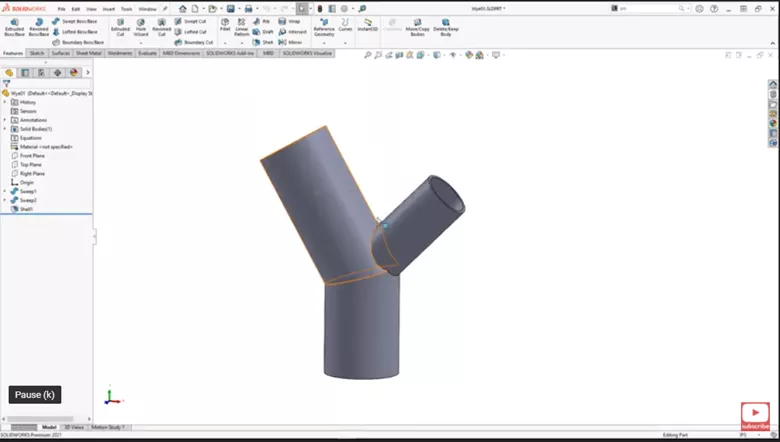
Figure 11. Smaller Diameter Branch
Another way to do this would be to model something similar to a reducer.
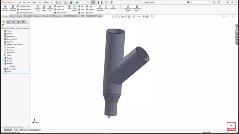
Figure 12. Wye Pipe with Reducer
If you have SOLIDWORKS Premium, you get access to the routing library. Inside the routing library, go to the reducers folder and open up one of the reducers. Looking at a reducer you can see they did things a little different with a sweep and a shell.
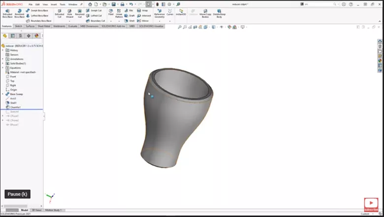
Figure 13. SOLIDWORKS Reducer
The part also had a lot of configurations so you can pick the sizer you need.
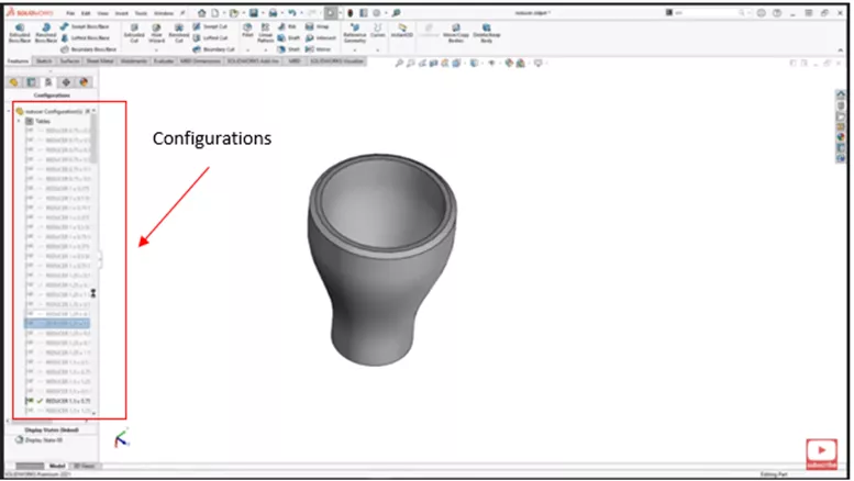
Figure 14. Configurations
For this part, we can just use a revolve. We can go in and create a sketch on the end we want the reducer.
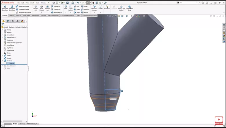
Figure 15. Reducer Sketch
In this example, we will add a little extrude at the end.
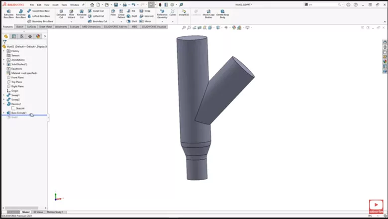
Figure 16. Add Extrude
Once added we can shell just like before and we have our wye pipe with a reducer.
When manufacturing the wye pipe with a reducer, keep in mind how you are creating this whether it be through casting or extruding PVC pipe. You might need to be able to get a plug out that is used to create the reducer.
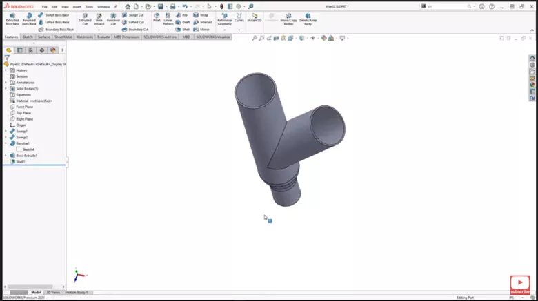
Figure 17. Shell
We hope this helps answer any questions about modeling Wye Pipes in SOLIDWORKS. Check out more modeling tips on our YouTube channel and the companion videos to this tutorial below.
![]() SOLIDWORKS - Wye Pipe Model Part 1
SOLIDWORKS - Wye Pipe Model Part 1
![]() SOLIDWORKS - Wye Pipe Model Part 2
SOLIDWORKS - Wye Pipe Model Part 2
More SOLIDWORKS Tutorials
Create J-Slots in SOLIDWORKS on Cylindrical Parts
Display SOLIDWORKS Sheet Metal Surface Area in Your Bill of Materials
How to Repair Broken References in SOLIDWORKS
SOLIDWORKS Sheet Metal Tab and Slot Tutorial
About Nathen Blas
Nathen Blas is a SOLIDWORKS Technical Support Engineer based out of our Headquarters in Salt Lake City, Utah. He earned his Bachelor’s degree in Mechanical Engineering at the University of Utah in 2018 and joined the GoEngineer family that same year.
Get our wide array of technical resources delivered right to your inbox.
Unsubscribe at any time.