Introduction to DimXpert in SOLIDWORKS
This article explains how to use DimXpert in SOLIDWORKS to insert dimensions and tolerances in 3D space so you can effectively share your design with others.
What is DimXpert?
DimXpert is a tool built into SOLIDWORKS that lets users quickly and easily dimension models in 3D space. DimXpert allows us to easily communicate sizes, locations, and tolerances so that other users can easily understand and manufacture our parts.
We can manually dimension selected features or automatically dimension an entire model using Auto Dimension Scheme (aka the 'easy' button). Third parties can then view the dimensions in SOLIDWORKS or export them in a specific format (e.g., a PDF).
How to Use DimXpert
The DimXpert tab is located in the column between the ConfigurationManager and DisplayManager on the left side of the screen. This is the default location, but its tools can also be accessed through the MBD Dimensions tab should you choose to enable it.
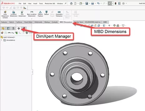
Basic DimXpert tool commands are available as icons in the DimXpert Manager. If you hover over them, a description will appear on the screen.
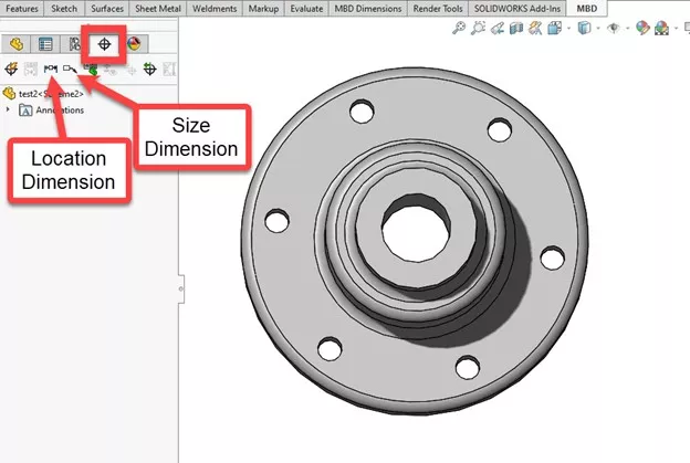
DimXpert Commands
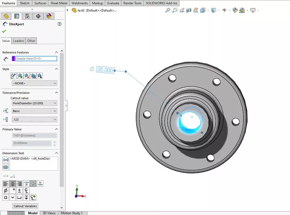
The Size Dimension tool lets us insert dimensions and tolerances for specific features such as holes. We can place the dimension anywhere in the graphics area.
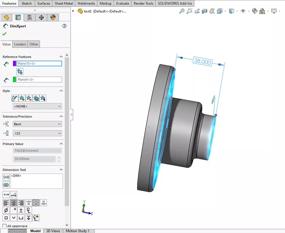
Location Dimension lets us specify the location of a feature relative to a datum, such as a plane. This can give us lengths of features in a format that helps in manufacturing.
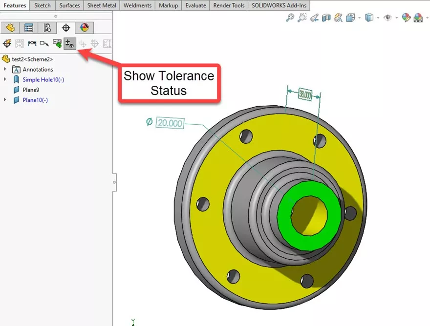
The Show Tolerance Status tool shows whether or not a feature is fully dimensioned. Green means that the feature is fully dimensioned.
- Suggested Article >> SOLIDWORKS MBD - Understanding DimXpert Colors
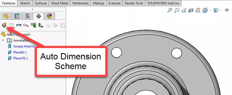
The Auto Dimension Scheme tool lets us automatically dimension the entire model with reference to specific datums.
To use the Auto Dimension Scheme tool, we must specify datums for SOLIDWORKS to use as reference points to dimension from. We can also specify which features to include or exclude.
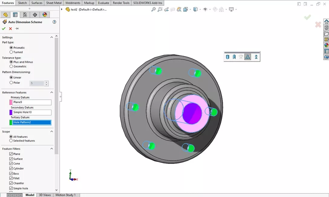
Click the green check and the dimensions populate. You can click and drag the dimensions to increase their visibility as needed.
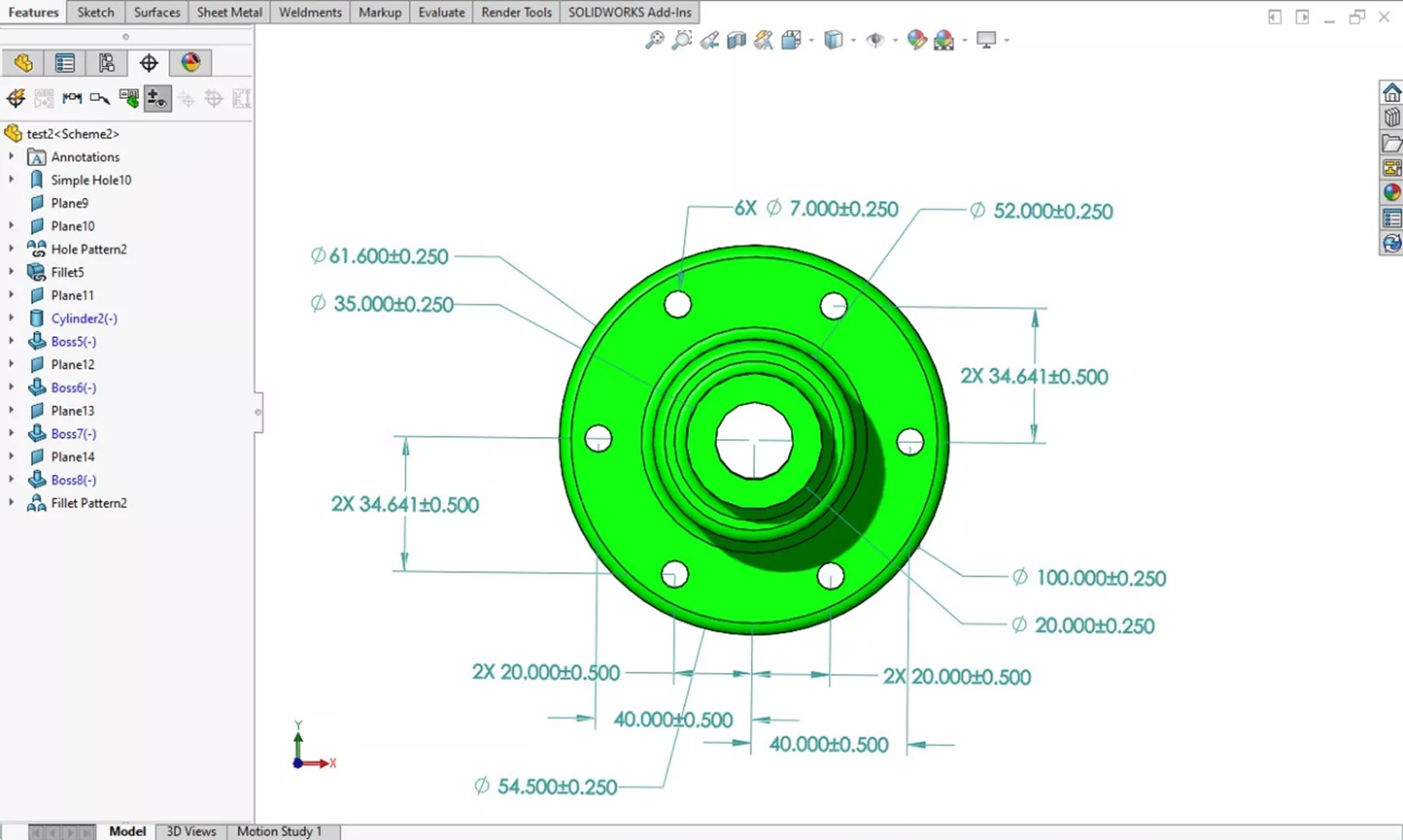
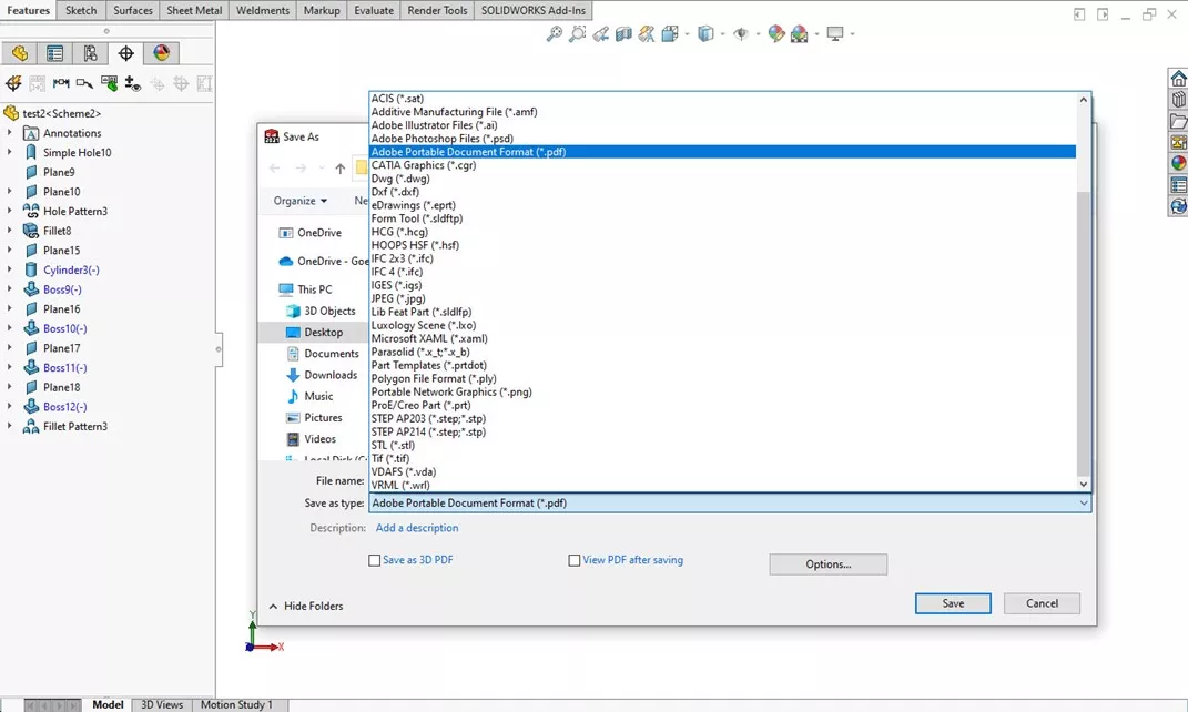
When the part is dimensioned, you can share the model or export it for non-SOLIDWORKS users. A simple File > Save As will let you save the current view as a 2D pdf. If you have a SOLIDWORKS MBD license, you can export as a 3D pdf as well.
I hope you found this tutorial helpful. Learn more about SOLIDWORKS by checking out more tips and tricks below.
More SOLIDWORKS Tutorials
SOLIDWORKS MBD - Understanding DimXpert Colors
Weld Bead vs Fillet Bead: SOLIDWORKS Feature Comparison
SOLIDWORKS Design Checker Tool Explained
Why is My Assembly Invisible in SOLIDWORKS?

About Gary Ballentine
Gary Ballentine is a Mechanical Engineer based out of our Headquarters in Salt Lake City, Utah. He earned a Bachelor’s degree from the University of California, Davis, a certification in Technical Writing from San Francisco State University, and a Bachelor’s degree in Mechanical Engineering from the University of Utah. Gary has been part of the GoEngineer family since April 2019 as a Support Engineer and Certified SOLIDWORKS Instructor.
Get our wide array of technical resources delivered right to your inbox.
Unsubscribe at any time.