Guide to Using Formlabs PreForm Software for SLA 3D Printing
With the release of Formlabs PreForm 3.43, GoEngineer’s suite of tools for advanced design and manufacturing has upgraded massively. The Form series of SLA printers are best-in-class additive manufacturing solutions serving industries from tailored dental solutions, to prototyping, and end-use production parts.
PreForm is the free job preparation (or slicing) software for Formlabs 3D printers, and works on Windows and macOS. With just a few button clicks, default settings and first-party resins produce reliable results. This article will guide users and designers through the ins and outs of PreForm in order to maximize surface finish, quality, and print speed beyond what the default settings provide.
In this article, I'll use a yo-yo SLDPRT with the GoEngineer logo on the side as an example.
How SLA Printing Works
Formlabs printers utilize a resin vat technology to create parts. A liquid photopolymer is dispensed into a tray, a build platform is lowered into the resin, and UV light is used to selectively cure the photopolymer in place. This means that parts come out “upside-down” from how PreForm displays your parts and how we generally think about 3D printing.
SLA prints are 100% solid and watertight as well as isotropic. Compare this to FDM and FFF processes, which are mostly hollow and when force is applied tend to fail along layer lines.
Keep in mind that the thermoset photopolymer resins used for SLA are neither the same nor have 1:1 substitutes for thermoplastics used in FDM, FFF, SLS, or SAF processes. Thermosets and thermoplastics both have advantages and disadvantages, but ensure that you have a suitable material choice if you are transitioning or using both technologies. Formlabs has a fantastic guide to SLA 3D printing to help you better understand the fundamentals.
Formlabs PreForm Job Setup
The first step is to launch PreForm after installing.
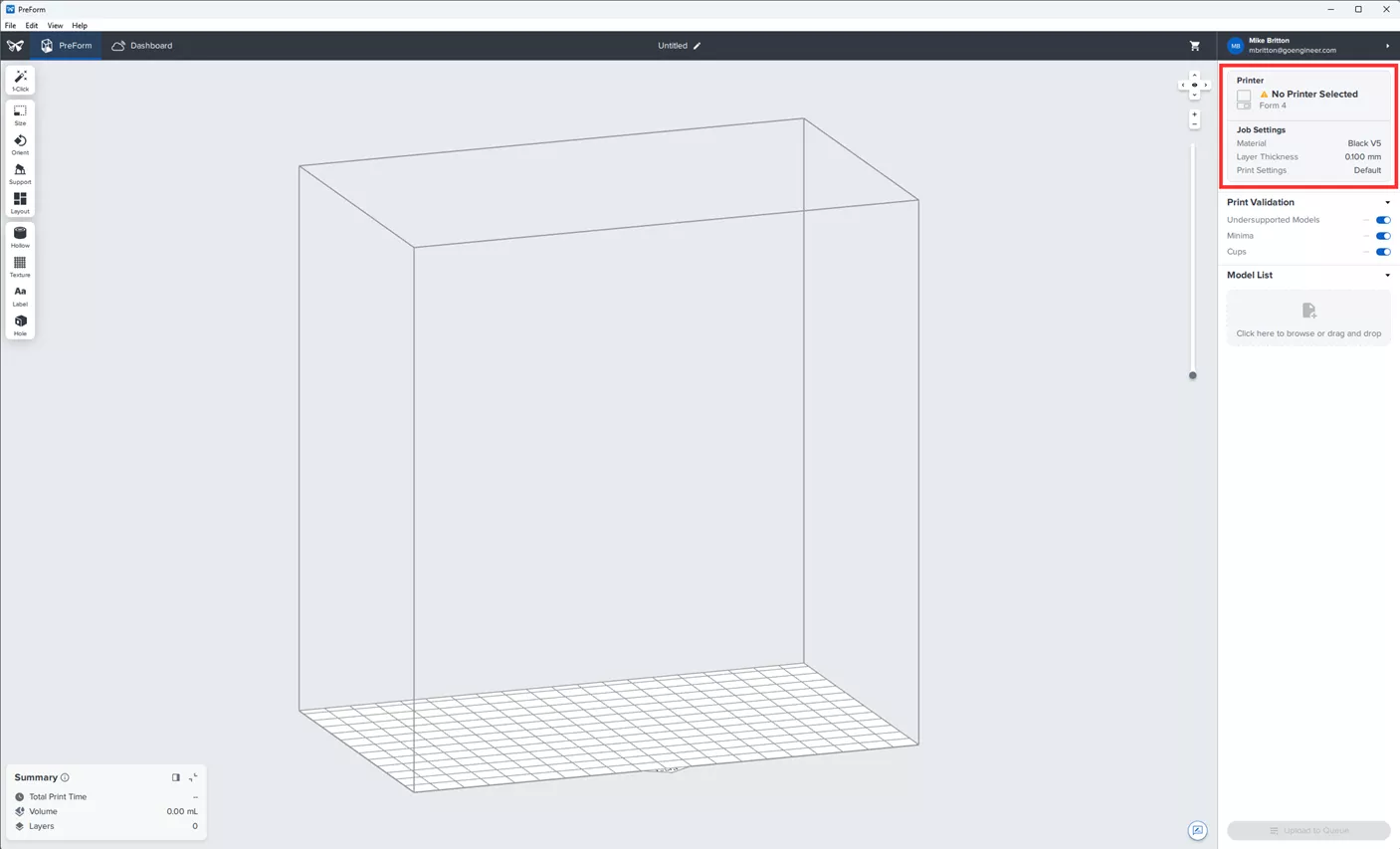
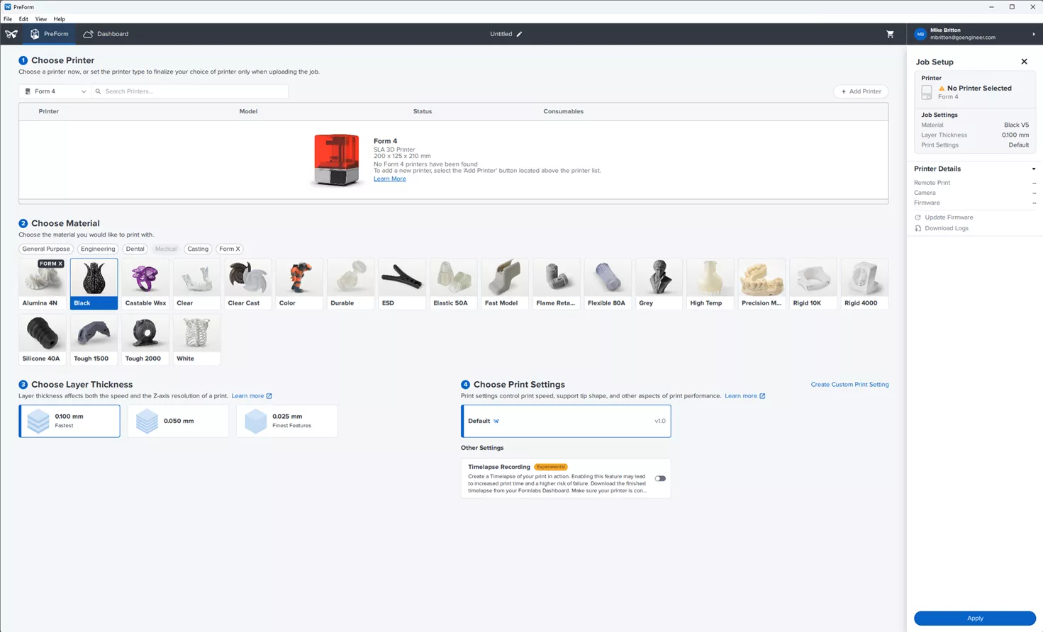
Ensure that the correct printer is connected or the correct model is selected if you are preparing a job off-network. Additionally, ensure that the correct resin is chosen.
Importing a File
With the PreForm 3.43 update in early December 2024, PreForm now supports not just mesh files, but also a wide variety of native CAD and interchange format files! This update brought the entire support list to:
- STEP (STEP, STP, STPZ)
- SOLIDWORKS (SLDPRT, SLDASM)
- CATIA V5 (CATPart, CATProduct)
- Creo (PRT, ASM)
- Jupiter Tessellation (JT)
- PreForm Jobs (FORM)
- Surface Tessellation Language (STL)
- Wavefront (OBJ)
- 3D Manufacturing Format (3MF)
These can be brought in via File > Open, or dragging and dropping a file into the Model List box.
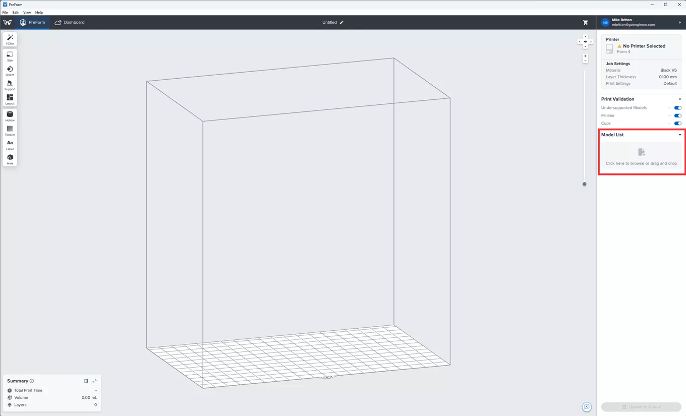
With the file imported, the software will run checks to see if a job will succeed.
One-Click Job Preparation
For beginner users, the 1-Click button in the top left corner is an invaluable tool. PreForm does an excellent job of automatically orienting your part and generating supports. Using the automatic settings promotes a very high likelihood of success. Print failures are generally a result of incorrectly orienting or supporting a model.
Do note that even these robust settings cannot overcome part geometries that have not been optimized for printing.
Clicking the Set Up Your Print button will do the following:
- Automatically orient your part.
- As discussed in the introduction, because a part is pulled “up” out of the resin, the process has to fight gravity.
- Automatically generate supports
- In SLA printing, supports are always necessary unless the designer has taken great care to design for this specific process.
- Unlike extrusion-based printing (FFF, FDM), supports are not regarded as a crutch or aid for poor design.
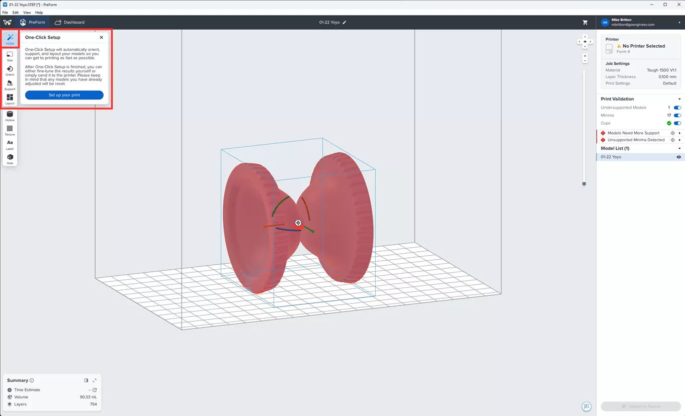
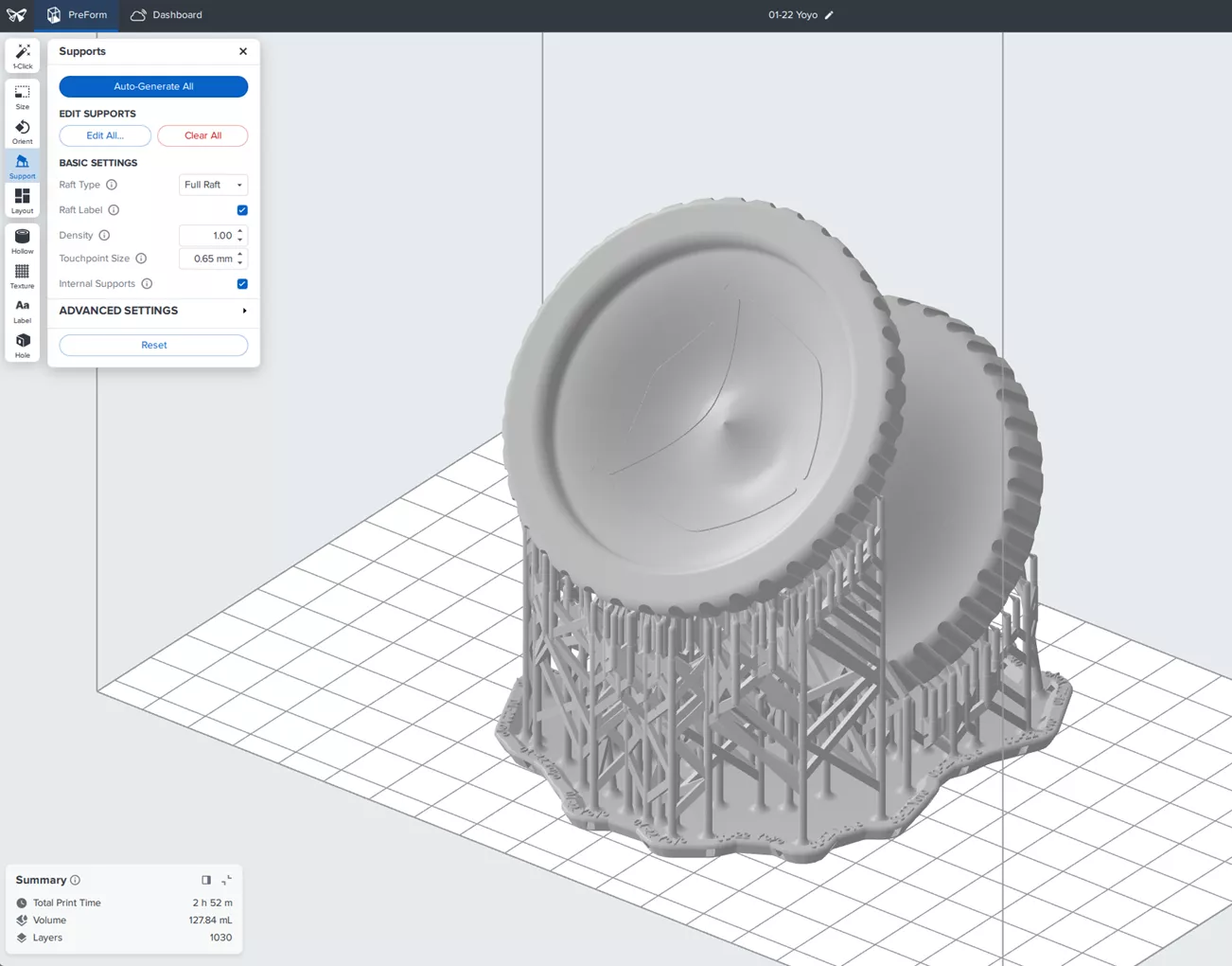
The results from the One-click Job Preparation button are shown below.
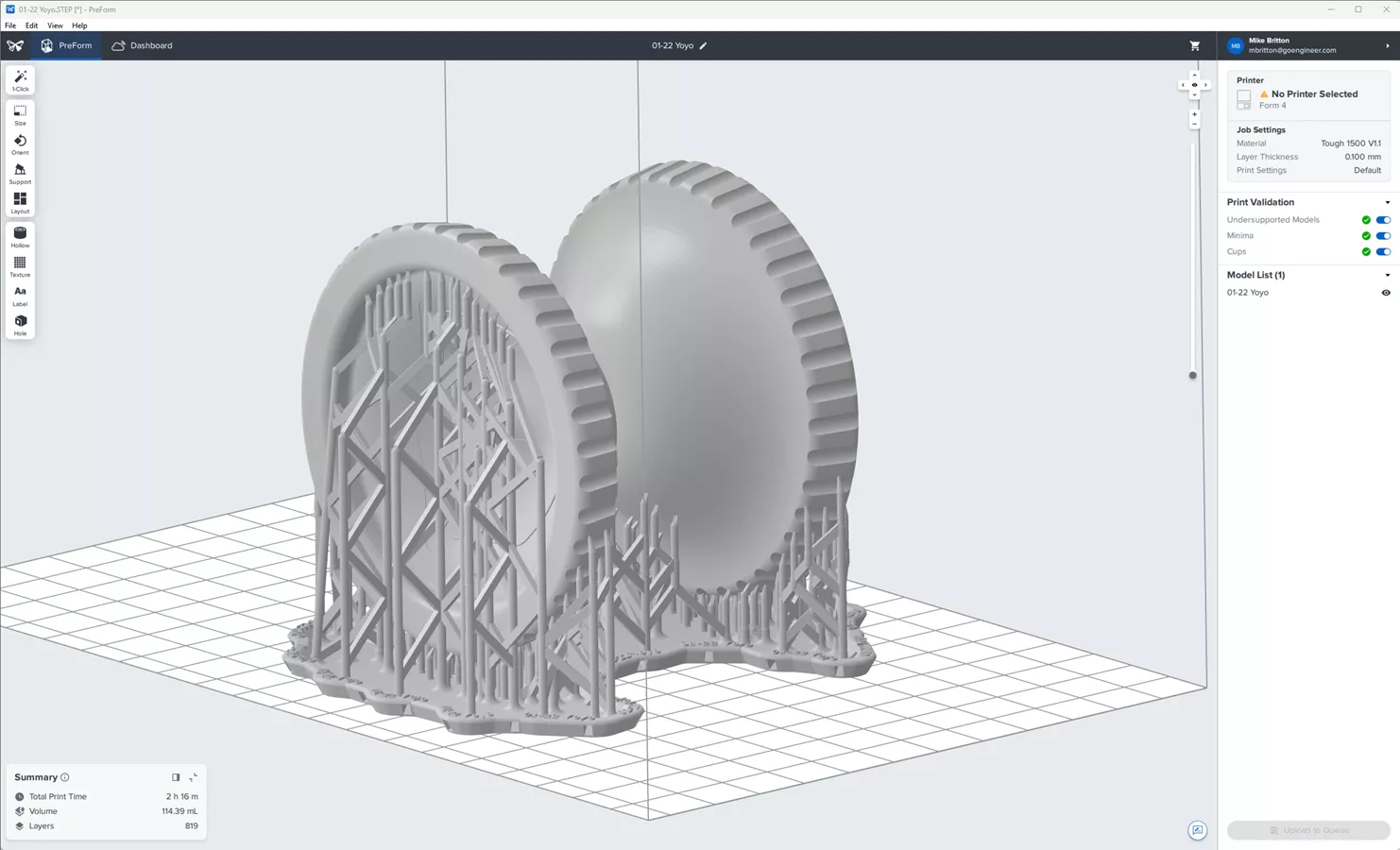
This part is ready to be uploaded to my Form 3D printer. As seen in the lower left-hand corner, this part will be complete in 2 hours and 16 minutes - not bad! Unfortunately, in this orientation, there are supports all over my GoEngineer logo on the yo-yo.
Manual Job Preparation
While the automatic settings are very good, manual job setups do have advantages. The advantages are primarily in the following categories:
Design Intent
The parts we make often have intention not captured by the geometry alone. Faces that have mechanical purposes or tight tolerances (e.g., bearing surfaces) may suffer from automatic orientation or pockmarks created by removing supports.
Surface Finish
End-use or customer-facing surfaces aren’t known to PreForm when using the One-Click Job Preparation button.
Model Orientation
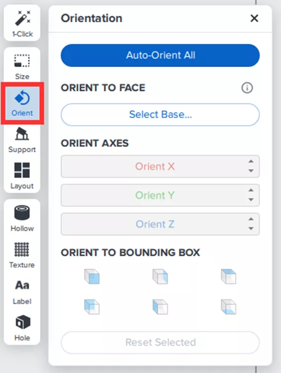
Formlabs have an exceptional guide on orienting models for success. Minimizing the cross-section of each layer of your job is an important element of ensuring quality. For this example yo-yo, orienting the model such that the finer detail GoEngineer logo is facing up. PreForm includes gross and fine controls over orientation both in the Orient dialog box and by clicking the model.
When manually tilting this part, we can see that I get a few error messages. PreForm does an excellent job of describing what needs to happen in order to fix these results and the possible consequences of allowing the error to persist. For now, I'll ignore errors relating to support.
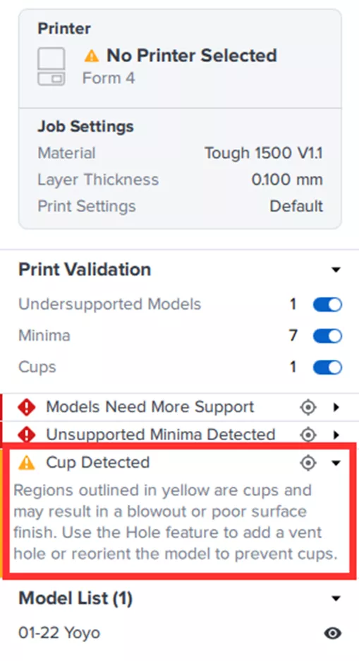
It is not always possible to eliminate every issue while preserving design intent or minimizing finishing steps. Use the layer slider on the right to check what kinds of issues you are experiencing, in this case, let’s look at the detail for cups.
A cup in SLA printing indicates an included area where additional suction forces may be created when peeling the plastic film of the print tray off your job. The layer height slider and cupped area of the print are highlighted in black for enhanced contrast.
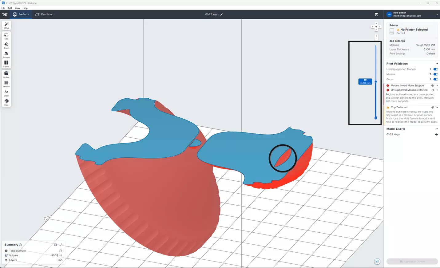
Using the up and down arrows on my keyboard, I can see that the current settings have a cup for 23 layers. Further tweaking the orientation may enhance print reliability and surface quality.
Support Generation
Even after manually orienting the model, I can still take advantage of PreForm’s exceptional automated support generation. Indeed, for most jobs I recommend starting with the Auto-Generate All button. Sometimes editing those automatic supports is useful, but oftentimes it does a great job on its own.
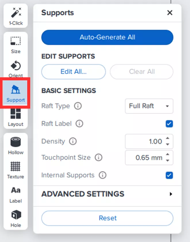
For more advanced users or perhaps for larger parts, click the Edit All… button to use advanced features like the support brush or you can click individual supports which may have been automatically generated in difficult areas.
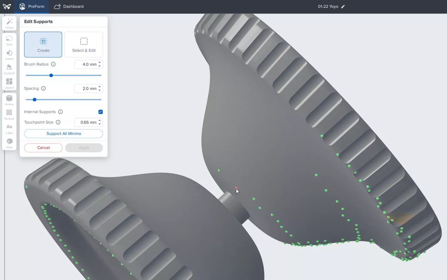
Support Touchpoints
In this Edit All dialog for support generation, you can see that each of these supports is represented by a sphere that intersects with the model, and that is exactly how they work.

If you want to change the size of the touchpoint, and therefore the blemish created by its removal, you need to be very careful about adjusting this radius. Recall the volume of a sphere is represented by the following equation:

This means that if you change a touchpoint from 0.5mm to 0.25mm, the strength is not just halved, but rather is even less than the cube root of the original! The fundamental point of this is that you cannot replace one large support with many weaker ones.
The optimal strategy for support placement is to find anchor points for large support contacts and then use finer supports throughout. Formlabs has a great article on advanced support settings.
When manually placing and generating supports, ensure that your spacing accounts for the resin at hand. More viscous resins like Tough 1500 or Rigid 10K need at least 1mm between supports and features in order to drain. Failure to drain can cause parts, supports, and features to fuse together. (View all Formlabs materials)
Additional Functions
Formlabs have a handful of very useful functions for their printers.
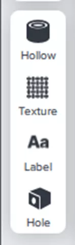
A brief explanation of these functions follows:
- Hollowing a part reduces the amount of resin used for creation. This is especially helpful for prototypes or first articles to ensure fit and finish without using as much material.
- Texturing allows you to use grayscale heightmaps to add a texture to a part.
- To ensure your part-as-designed is your part-as-manufactured, simulate and validate in CAD. Consider using tools like SOLIDWORKS 3D Textures, Visual Scripting, or Lattice Design.
- Labeling embosses the filename on the support raft.
- Holes allow drainage for hollowed parts, or to create vents for areas with cups.
Using manual orientation has added 36 minutes to my print time, however, I may have saved that in careful sanding and filing to remove support marks from the engraved face.
I hope this introduction to Formlabs PreForm workflow and quick advice was helpful. Contact us for further information about Formlabs or our other additive manufacturing and design for additive manufacturing solutions.
Related Articles
GoEngineer Adds Formlabs Products to its Solutions Portfolio
How to Add Users and Assign Training in the GoEngineer Customer Portal
Economic Change in Manufacturing Demands a New Approach by Leveraging 3D Printing

About Mike Britton
Mike Britton is a SOLIDWORKS Application Engineer based out of Ontario, Canada. In addition to his work with GoEngineer, Mike is a competitor on Discovery Channel's BattleBots and volunteers with his childhood summer camp & local makerspaces.
Get our wide array of technical resources delivered right to your inbox.
Unsubscribe at any time.