Fix Failed Mesh in SOLIDWORKS Simulation
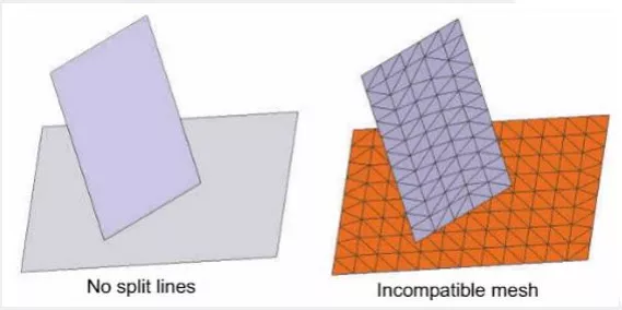
When a SOLIDWORKS part file, multibody part file, or assembly fails to mesh, there are a series of troubleshooting steps we can take. Failed mesh usually occurs due to one of three reasons:
- There are interfering bodies or parts
- The mesh element size is larger than a face or feature in the body or part.
- Incompatible mesh is required
Valid Geometry
The mesh can fail for broken or interfering geometry. Use Tools > Evaluate > Check to test for sliver faces, or invalid faces or edges. Use Interference Check in an Assembly document to find which parts are interfering.
Mesh Element Size
Begin by making sure the mesh element size is small enough for the part. Keep in mind that if mesh becomes too small, we could run out of RAM or cause very long solve times.
Switch from Standard Mesh to Curvature-Based Mesh
Standard mesh is the default mesh. It keeps the same element size throughout the entire part or assembly. Curvature Based mesh reduces element size around small holes and curved faces. Right-click on Mesh > Create Mesh > Mesh Parameters.
Reduce the Max and Min Element Size
In Create Mesh, push the slider towards fine. This generally reduces the max element size.
Open the part or body in its own part file and create a Simulation study for it. Run a curvature-based mesh on the part. Likely, the default values (seen in Mesh Parameters) guessed by the program will succeed. Note down the min element size and use it in the assembly.
Apply Mesh Control
Mesh controls refine the mesh on points, edges, faces, or bodies. Unless you are sure of which feature is causing the mesh to fail, generally, we apply mesh control to entire bodies while troubleshooting.
In the Parts dropdown, there are icons next to each body or part. If the icon is green the mesh succeeded, if the icon is red the mesh failed. Right-click on failed parts and choose Create Mesh. This activates Mesh Control and selects the entire body. Make at least 2-3 attempts while reducing mesh control element size.
Incompatible Mesh
SOLIDWORKS Simulation will attempt to line up the mesh nodes where parts touch. If the two part geometries are very different, for example, a cylinder sitting on a flat plate, lining up the nodes will fail, causing the mesh to fail on the part. In Create Mesh > Advanced Options, hit the checkbox for Remesh failed parts with incompatible mesh. Right-click the study name > Properties. In the Options tab, Incompatible bonding options, choose More accurate (slower).

Narrow Down the Problem
Specifically, where part files are not meshing, and we can’t tell where the problem may be, take advantage of Suppress or Split.
Suppressing features in the tree will simplify the model, we generally find a particular feature is triggering the part to not be able to mesh, for example, a feature that creates small pilot holes or small fillets.
In complex part files that may have hundreds of features, or may have been imported, the Split feature is useful. Use sketch lines or planes and Insert > Features > Split to carve the part file into multiple bodies. We will find that some bodies will mesh and some will not. Thus we have narrowed down the problem areas and can either modify geometry or use mesh controls to complete the mesh. Ultimately Split is just a troubleshooting technique, and should be deleted once we know how to fix the problem area.
Related Articles
How Do I Know My Mesh is Good Enough?
Using Sheet Metal Bodies in SOLIDWORKS Simulation
SOLIDWORKS Simulation Solution Adaptive Mesh Refinement
SOLIDWORKS Flow Simulation: Solution Adaptive Mesh Refinement

About Shivani Patel
Shivani has a background in aerospace engineering, and is the Engineering Manager for southern Texas. She has the Elite certification in SOLIDWORKS and is happy to jump into anything in the SOLIDWORKS licenses. Her main specialty is Simulation - and has spent the past 6 years digging into the Motion Analysis, FEA and CFD programs and supporting many of our oil and gas customers in the south.
Get our wide array of technical resources delivered right to your inbox.
Unsubscribe at any time.