3DEXPERIENCE Lattice Designer Technical Deep Dive
The 3DEXPERIENCE platform is Dassault Systèmes' tool that brings the entire engineering and manufacturing workflow from conception to obsolescence under a single umbrella. The objective of the platform is to make the 3D model the source of truth for anything someone at a company needs to know or do about the product.
This means there is a closed loop for every stage of product development. Specifications, concept models, prototypes, simulation results, manufacturing data, and so on are all linked to the same product model.
With this context in mind, Dassault Systèmes has developed a tool for designing lattices for additive manufacturing. The webinar above explains how CATIA Lattice Design uniquely combines the strengths of our traditional Boundary Representation (BREP) CAD tools with new and advanced Signed Distance Field (SDF or Implicit Modeling) design tools. In addition to technical details, the webinar demonstrates live clicks for designing latticed parts.
Why is Lattice Designer Important?
3DEXPERIENCE Lattice Designer is unique for a few reasons:
- It non-destructively creates lattices in your parts.
- There is no degradation to a mesh and maintains full associativity to your original designed part.
- There are no import/export musical chairs.
- If you adjust the dimensions in your original designed part, your latticed part will automatically update in the background without having to re-launch Lattice Design.
- Your parts designed for additive manufacturing can be validated, defined, managed, and manufactured entirely in-platform.
- If you need to revise your design, everything from your simulation setups to print job prep, drawings, and CAM can be updated to your latest revision.
- You get parametric control over wall thicknesses and lattice parameters, thus ensuring that the same lattice specifications regardless of geometry have reproducible results.
- We can even parametrically optimize our lattice specifications through simulation.
In environments where reproducibility, adherence to specifications, and minimizing rework time between iterations are key, we get a lot of advantages.
What Can I Do With Lattice Designer?
Lattice Designer is a single license that can be purchased on its own. It can also have its capabilities extended with other 3DEXPERIENCE licenses (or roles). Each version gets its own section.
Lattice Designer on Its Own
The Lattice Designer license comes with a handful of applications, all of which are installed on your Windows machine. Below is a screenshot of what comes with it.
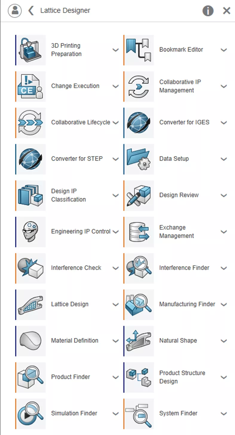
Most of these applications are designed around data and standards management as well as import/export tools. This section will focus on the design tools, Natural Shape, and Lattice Design.
Natural Shape
Natural Shape is a great tool, and it is intended to make geometry as rapidly as possible. It is a direct-editing environment, so there is no feature history as you construct or edit your design.
Natural Shape is enormously useful for creating simple designs or preparing an already designed part for 3D printing. Adding fillets, creating pockets, or changing dimensions to prepare for machining after printing are all super easy tools. Features you might expect like shells, drafts, blends, splines, patterns, and more are available.
Even advanced geometry manipulation tools like doming, mesh deformation, and generating a middle curve between two edges or curves are available.
Whether you are starting from scratch or importing a file, the first step is to determine the “Industrial Context” – this term is essentially asking, “Are we making nanomachines or starships?” and it assigns the appropriate units. The imported part recommendations are usually pretty good.
Once you're in the tool, you can modify parts using context menus to move faces, and the pane on the right-hand side gives you space for dimensions. Sketching is available, and surfaces are automatically generated in closed contours, which makes it extremely easy to create cutting elements for partitioning lattice cavities.
Natural Shape is a robust design application, and impressive non-history-based designs can be made in this direct modeling environment.
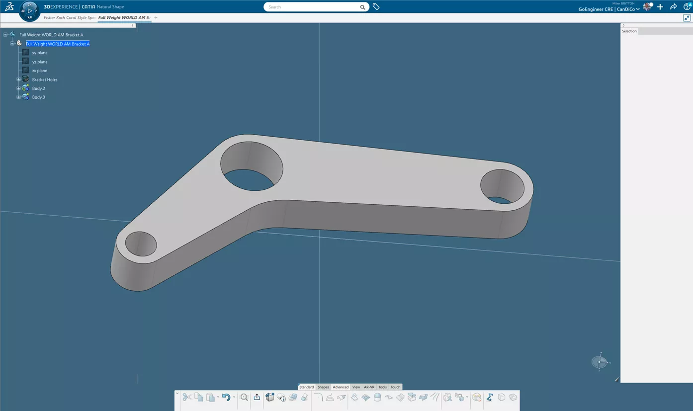
An imported part in Natural Shape
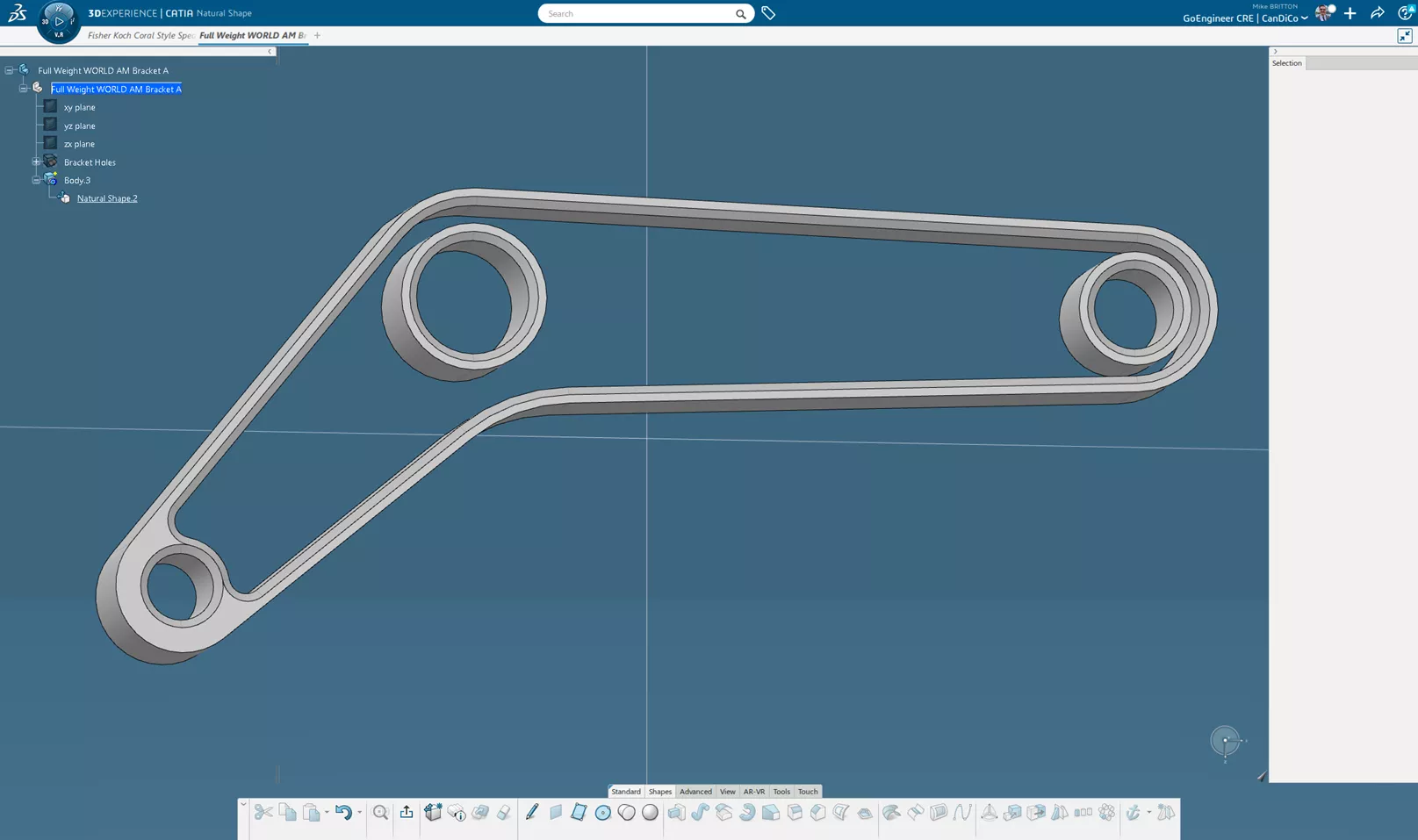
The same imported part prepared for latticing in Lattice Designer
Lattice Designer
This application is the headliner of the role and enables you to actually create the lattices. The application allows you to create your own lattice cavities within the Lattice Designer role, or to further modify designs after going through Natural Shape.
There are myriad ways to accomplish these workflows, but in this example, I would like to note a few concepts about the features in Lattice Designer:
- The Lattice Design Assistant is a guided workflow that will allow you to create your lattices.
- In the Lattice Design Assistant, Help Documentation, and in the Action Bar features, there are callouts for Volume features, such as Volume Extrude and Volume Close Surface. Unlike SOLIDWORKS and many other CAD packages which only recognize “Solids” and “Surfaces”, these CATIA roles also recognize Volumes as a separate kind of entity.
- This restricts the kinds of features that can be done to these bodies, which is important to keep in mind if you choose to extend your Lattice Design capabilities with other CATIA roles.
- Volumes are essentially manifold surface bodies and can be modified or created in Natural Shape.
- The Lattice Design Assistant explicitly requires cavities for latticing to be defined as volumes, not solids.
- Lattice Design has basic sketching tools, but unlike Natural Shape has the full suite of constraints and so on.
- Multiple Extract essentially allows you to duplicate faces or surfaces from surface bodies, solids, and volumes to define lattice cavity volumes.
- Partition allows you to cut volumes with volumes or other surfaces to define lattice cavity volumes.
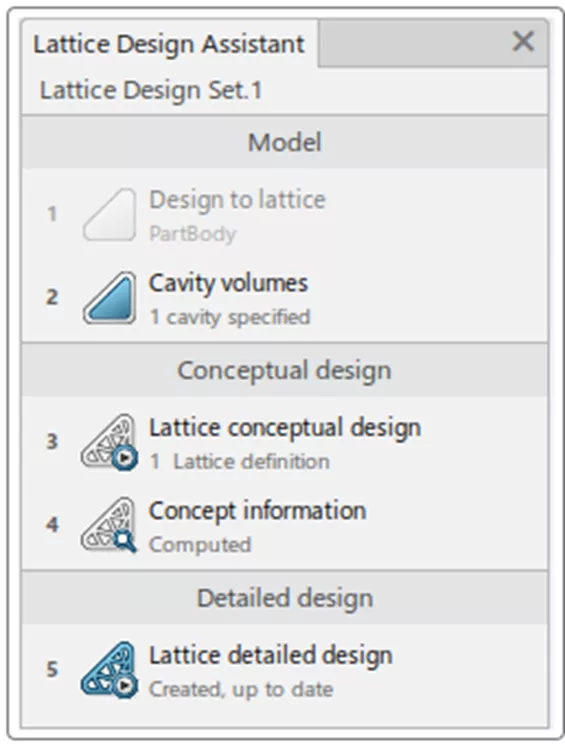
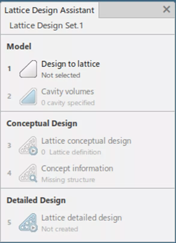
The Lattice Design Assistant. Note the specification of “Cavity Volumes”
Capabilities
The Lattice Design tool on its own can create a variety of Bars-and-Points lattices, usually defined by crystalline structures. These can be generated in rectangular or circular arrays.
Also available are Triply Periodic Minimal Surfaces (TPMSes). Gyroids, Neovius, Fisher-Koch, and others.
The workflow goes from selecting a design, selecting (or creating) a cavity volume or volumes, defining the lattice structure on a per-volume basis, and generating the lattice. Users can optionally create concept information to learn about weight savings.
Sample Workflow
This sample workflow is different from the one in the webinar, though they use the same base part. This is to illustrate just two of a variety of workflows the Lattice Designer role enables us to utilize!
Starting with the graphical example from the Natural Shape section, I will take this part in progress and create the lattice. After clicking the Lattice Design Assistant button, the first step is to create a Lattice Design Set. You can create multiple design sets from a starting design if you want to explore a variety of lattice structures or parameters.
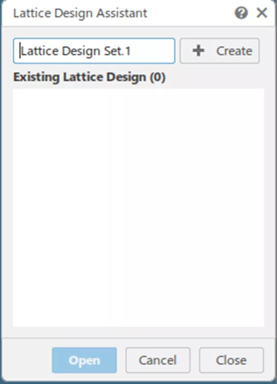
The first step of the Lattice Design Assistant
From here, simply follow the steps of the Lattice Design Assistant. First, choose a design to lattice.
Looking at the Spec Tree, any of the Part Body sets, Geometrical sets, or Ordered Geometrical sets are an option. Following my workflow coming out of Natural Shape, I will choose the set renamed as Natural Shape Body.
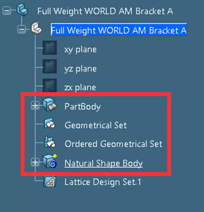
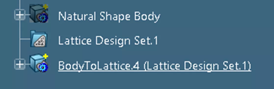
We can see that when I created my Lattice Design Set, it added one to the Spec Tree. When I choose the design, it adds a “BodytoLattice” body under that.
At this stage, I can use the features in the Lattice Design Exploration tab in the Action Bar at the bottom of the screen to define a cavity. Currently, the empty space inside the bracket is insufficient to define a cavity volume.
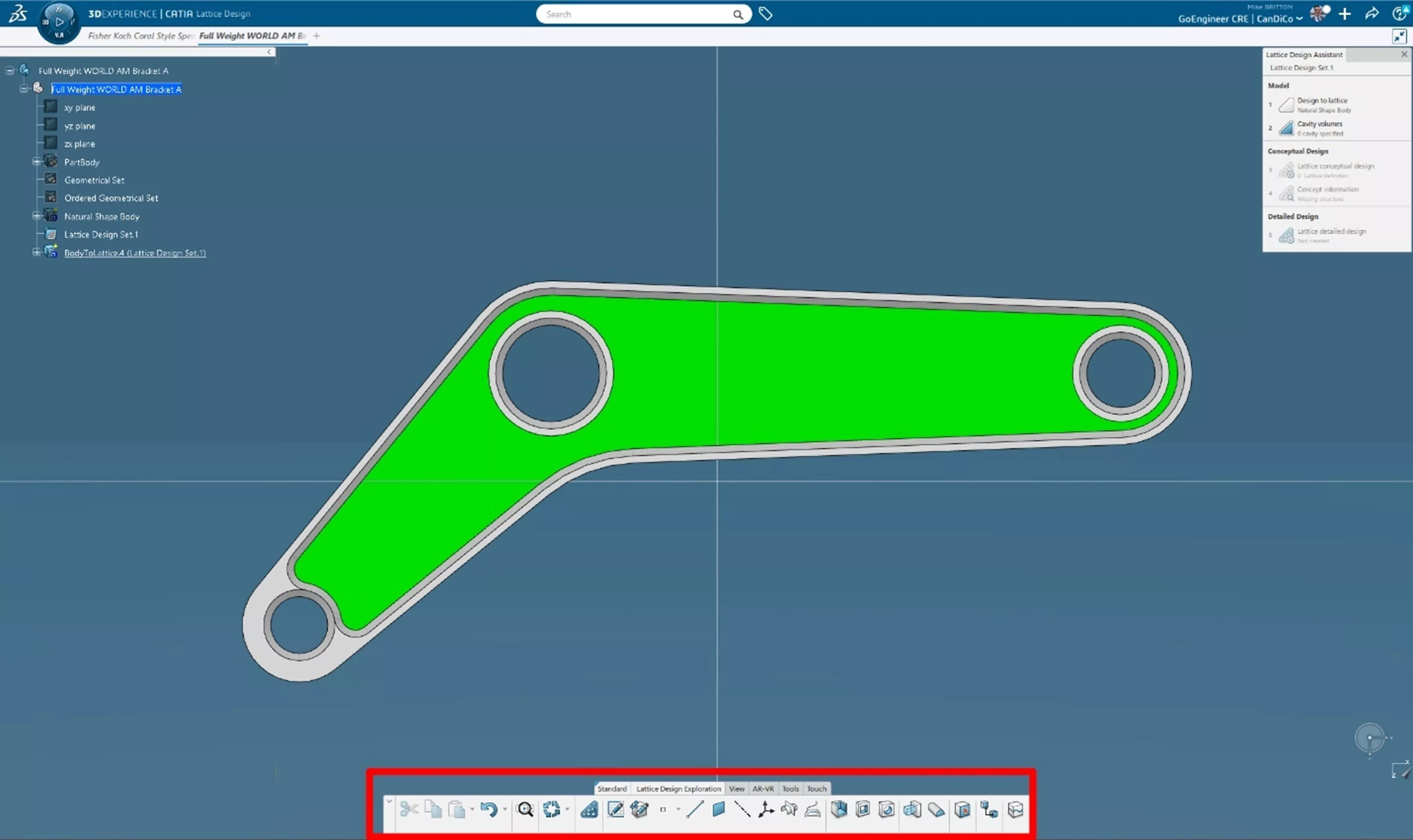
I will use the features in the Action Bar (highlighted in red) to create my Cavity Volume in the green area.
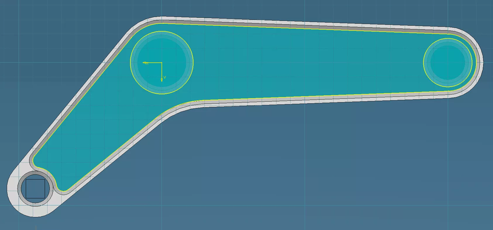
I will create a plane to sketch on between the top and bottom planes of the bracket using the Plane command. On that plane, I will place a positioned sketch and project the 3D entities of the inner edges of the bracket and cylinders defining the walls of the tubes. Projected sketch entities are rendered in yellow by default in 3DEXPERIENCE CATIA roles.
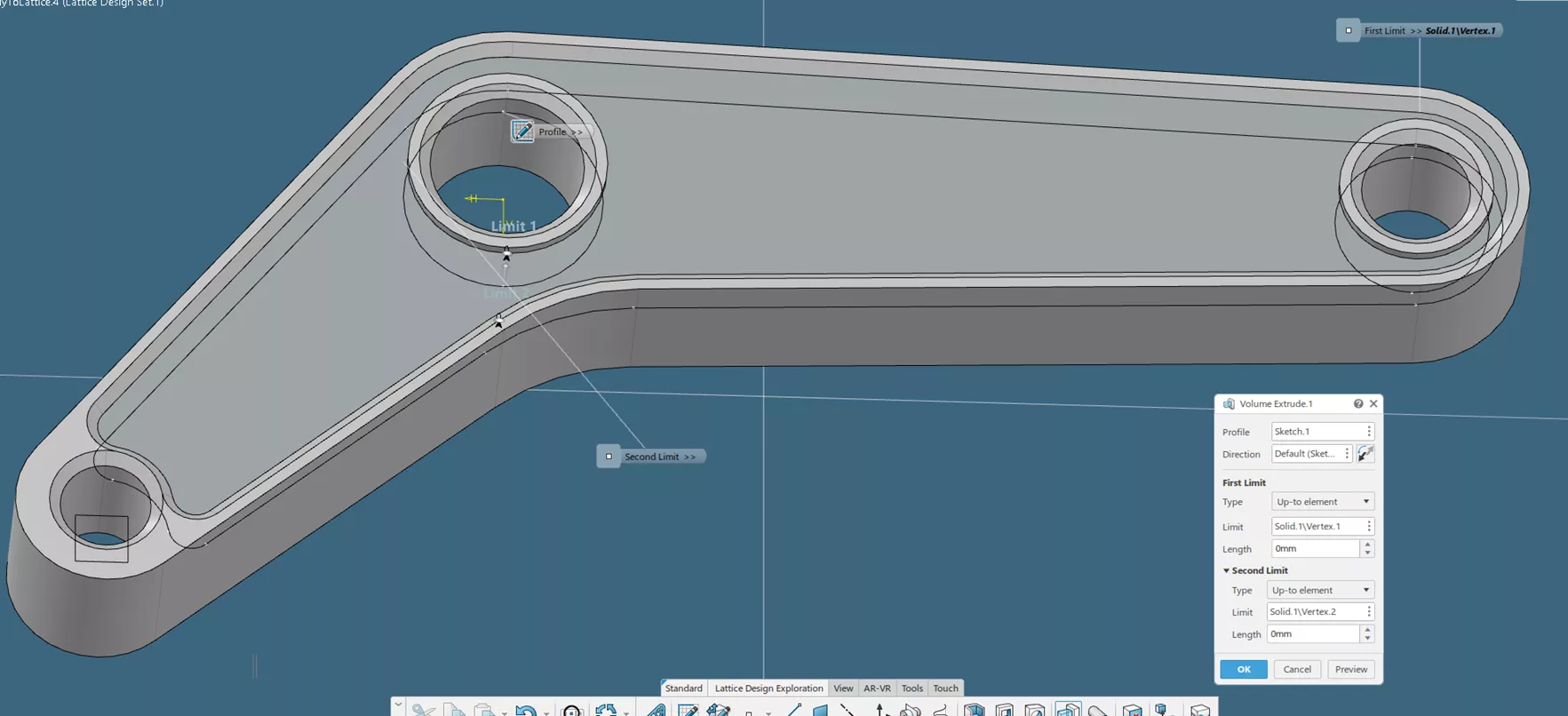
I will then use the Volume Extrude feature to extrude the above profile up to the bottom of the chamfers. By using the Project 3D Elements and Up to Element conditions in these steps, I will ensure that if I change my design in Natural Shape, it will associatively update my lattice.
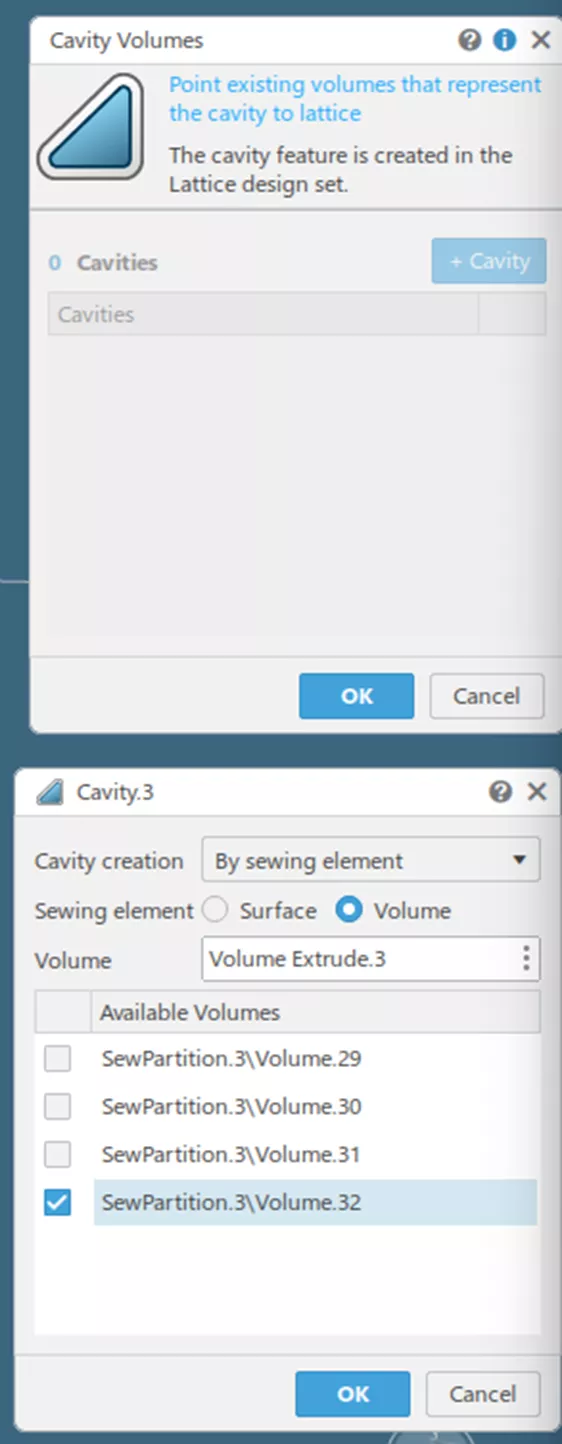
Having created them, I can now define the Cavity Volumes. By hitting the Cavity Volumes button, I need to define this Volume Extrude feature as the desired area to lattice.
Inside the Cavity Volumes command, I will click + Cavity. Since this volume is going to be used as a bridge between entities that are not touching one another, I will choose By Sewing Element inside the dropdown options then the Volume radio button since this was created using the Volume Extrude command.
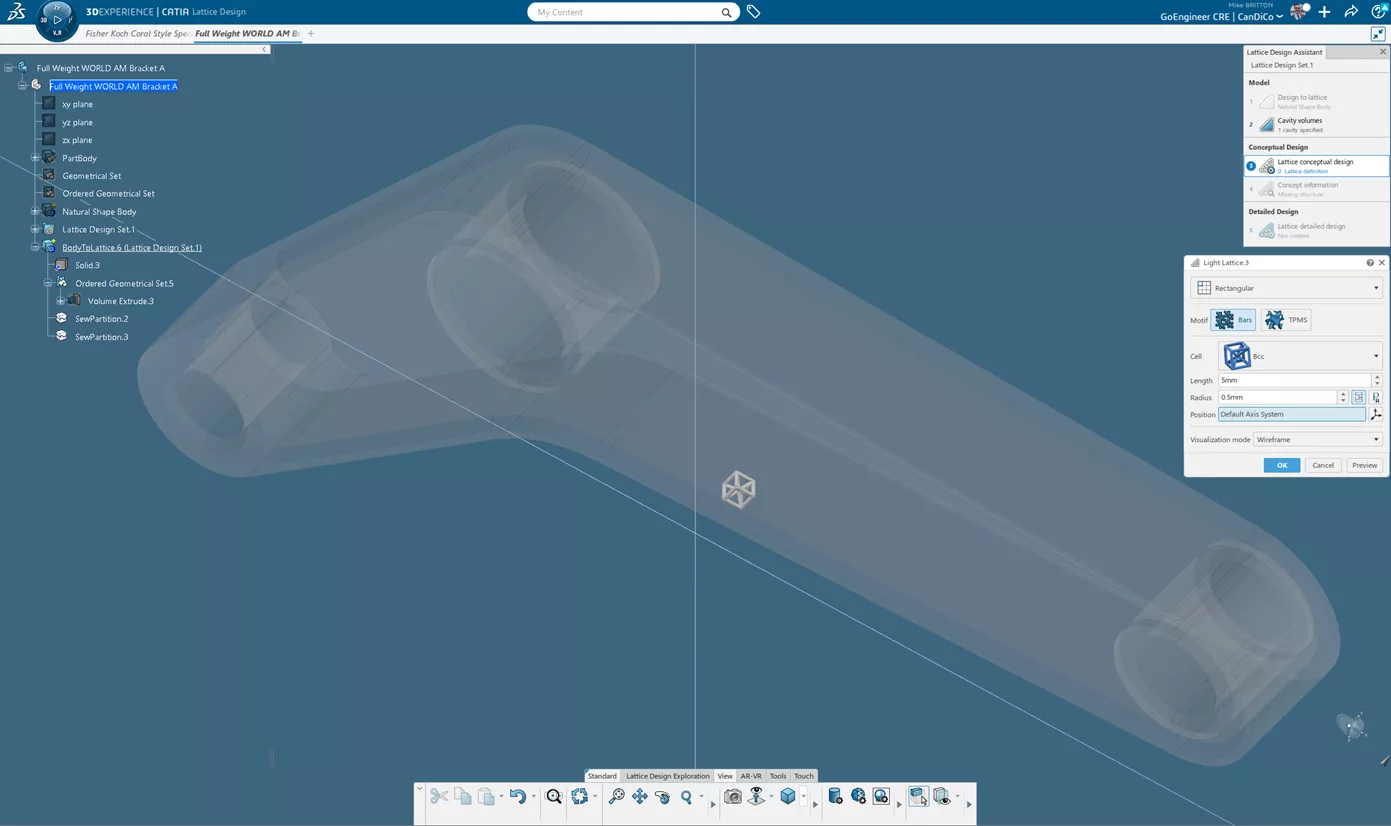
I will now hit OK and work on my Lattice Conceptual Design! By default, Lattice Design will propose a size of unit cell. For this, I will use the suggested Bcc lattice structure with the suggested 5mm length and 0.5mm bar radius. Do note that if you would like to use a TPMS you can click the “TPMS” motif option.
The Light Lattice dialog box will present a preview of the unit cell so I can get an idea before my workstation starts doing heavy lifting.
Once I hit OK, Lattice Design will begin updating the topology and provide a preview. Click the Concept Information button in your Lattice Design Assistant dialog to see an approximation of weight savings.
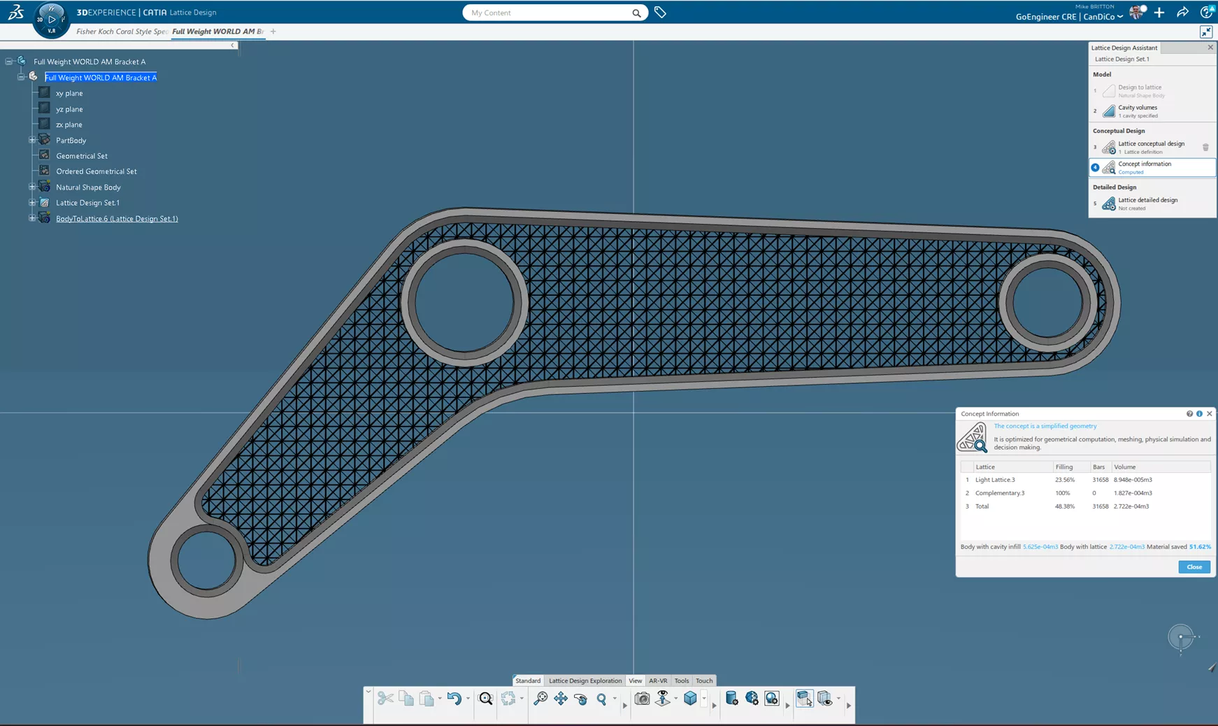
Savings of 51.62% are estimated, full details can be found when a material is applied after latticing is complete.
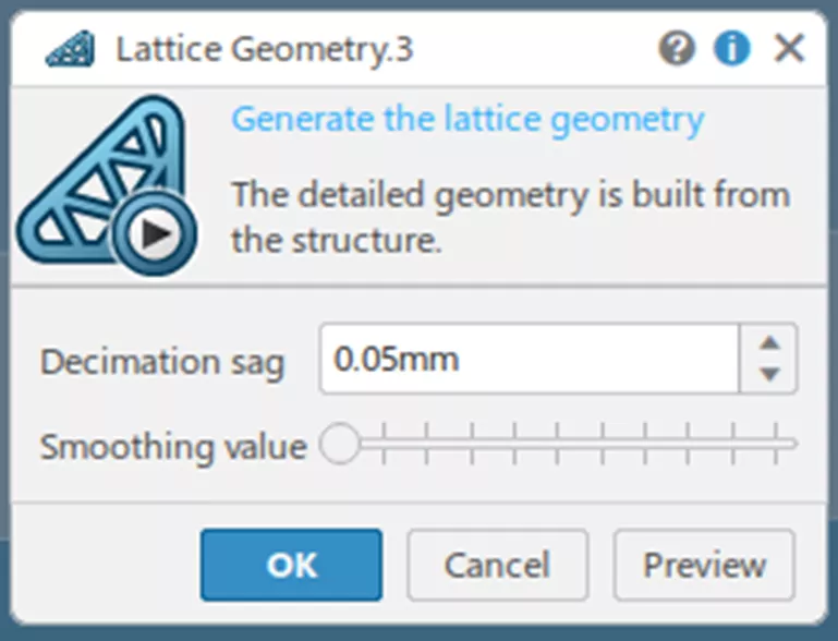
I can finalize my lattice design and get my polyhedral output by hitting the Lattice Detailed Design button.
The final dialog box asks you to indicate your decimation sag, essentially the roughness of your model going from NURBS to polyhedral. The smoothing value also manages your fidelity to the original model. The higher the smoothing value, the more the polyhedral deviates from the original model as well.
The finer and smoother you make the values, the longer the processing time takes, so just bear that in mind when creating demonstration units or prototypes. I set my options to be extremely fine.
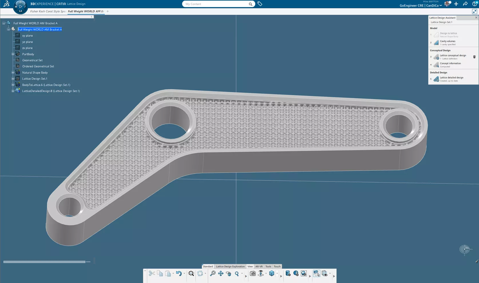
After your inputs are determined, CATIA does the rest! My final result from this workflow.
Extending Lattice Designer with Additional Roles
Lattice Designer is an extremely powerful tool with what it has available. It generates high-quality lattices which can be deformed in polar arrays, or even conformal TPMS structures with varying cell sizes and thicknesses!
Beyond this, however, there is a wide range of capabilities you can branch out to. Below is a brief list of some of the roles that can extend your lattice design capabilities.
Simulation
Starting with SIMULIA Structural Analysis Engineer, you can run design studies not just on your latticed parts, but also structural simulations on traditionally designed parts. With the Structural Analysis Engineer role, however, you can automatically parametrically optimize your lattice parameters in order to manage the anticipated loads the part will see in use.

Design
The Design domain includes a wide variety of roles that can impact your abilities:
Function Driven Generative Designer
Function Driven Generative Designer is an entry-level generative design role. This role provides basic solid modeling capabilities, advanced surfacing tools, and generative design based on simulated loads.
Additionally, the advanced surfacing tools in this role allow for more advanced cavity volume geometry creation.
Mechanical & Shape Designer and Mechanical and Shape Engineer roles have even further expanded surfacing tools in a part engineering environment.
This role allows you to take the generative designed shapes and optimize them for additive manufacturing. Combining these Design for Additive Manufacturing (DFAM) capabilities with Lattice Designer’s capabilities, it dramatically simplifies making optimal parts.
Visual Script Designer
Visual Scripting is an entire rabbit hole of its own advanced design capabilities, however, the most relevant one is that when a user has both Lattice Design and Visual Script Designer roles they can design their own beam lattice specifications. This enables the creation of digital foams for filtration or elastomeric applications, and its workflows can be used to create custom operators such that these parameters are saved for rapid reuse in the future.
Note: This extremely powerful role uses a very different interface from other tools, it is a node-based scripting interface.
Manufacturing
After parts are designed and validated, they need to be printed! Additive Manufacturing Engineer and Powder Bed Specialist are two dedicated job preparation roles for 3D printing.
These roles can do everything from 3D nesting, labeling, cages, and build processors that speak directly to Additive Manufacturing machinery. Saving rules for rapid reuse and complete repeatability on your 3D printers are critical components of ensuring that your additive manufactured parts come out perfectly.
Conclusion
There is a ton of information to take in with 3DEXPERIENCE’s Additive Manufacturing capabilities, and I hope this introduction and walkthrough with Lattice Designer shines a light on that. If you have any questions about 3DEXPERIENCE Lattice Designer or anything else disucssed in this article, I encourage you to contact us and share what you’d like to accomplish so we can get you there!
Related Articles
Benefits of Model-Based Systems Engineering (MBSE)
CATIA V5 to 3DEXPERIENCE CATIA: Tips for a Successful Transition
6 Reasons Designers Upgrade to CATIA
Advantages of 3DEXPERIENCE CATIA

About Mike Britton
Mike Britton is a SOLIDWORKS Application Engineer based out of Ontario, Canada. In addition to his work with GoEngineer, Mike is a competitor on Discovery Channel's BattleBots and volunteers with his childhood summer camp & local makerspaces.
Get our wide array of technical resources delivered right to your inbox.
Unsubscribe at any time.