What is SOLIDWORKS Flow Simulation Used for? Top 5 Use Cases
SOLIDWORKS Flow Simulation is a multipurpose computational fluid dynamics (CFD) tool directly integrated with SOLIDWORKS 3D CAD. In this blog, we’ll showcase the top five fluid flow scenarios. These use cases outline how Flow Simulation can help answer your toughest design questions.
Thermal – Electronics Cooling
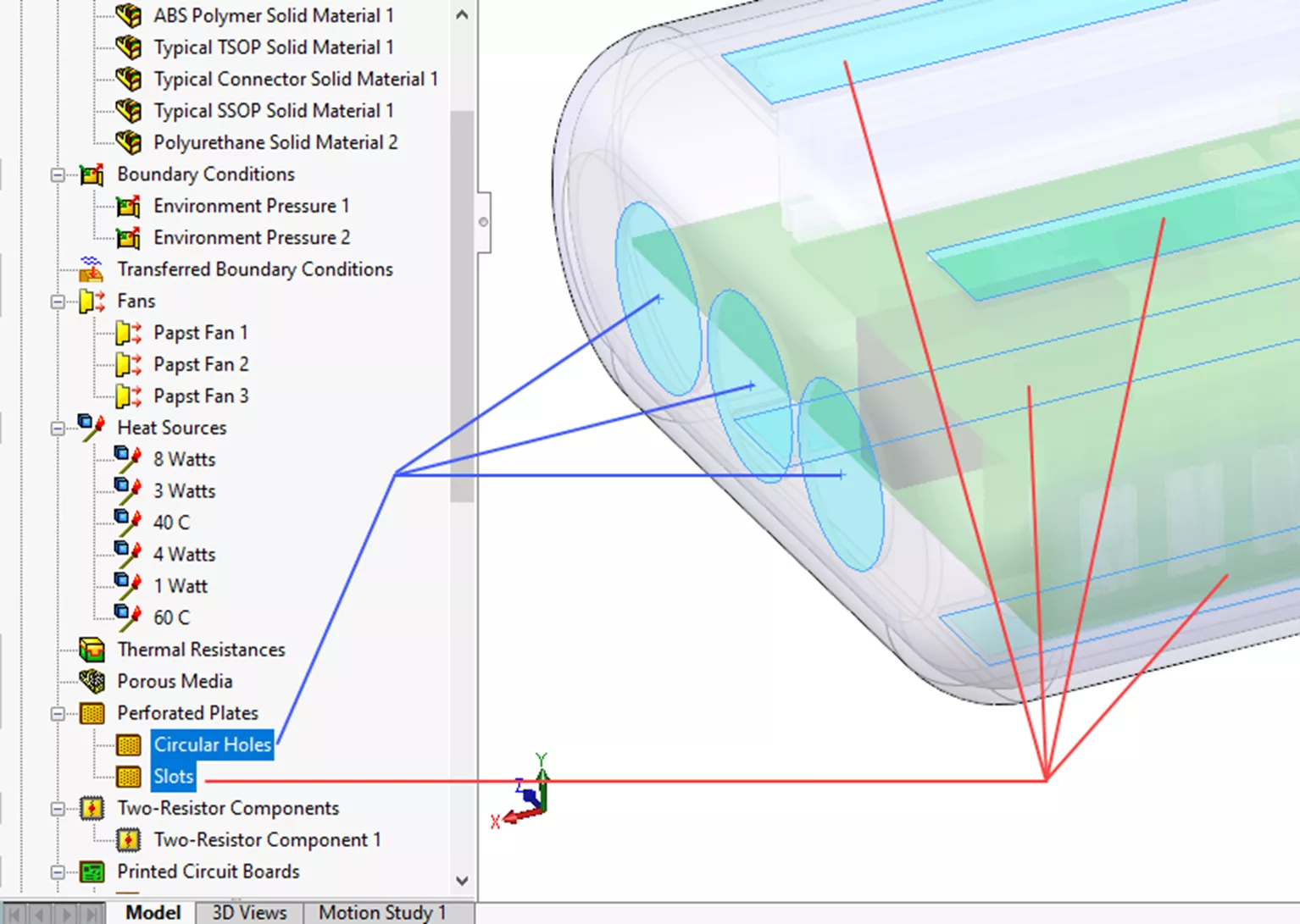
This electronics enclosure will be treated as an internal domain. The study will consider the flow field inside the enclosure. In this type of study, we consider the inlets and outlets as boundary conditions. For this example, the inlet flow conditions are defined by fan flow pulling in external ambient air. The fan flow is specified with a fan curve provided by the fan manufacturer.

The outlets are perforated plates open to the ambient environment. Along the top and bottom, there is a slot pattern. There are also circular patterns of holes on the opposite end from the inlet fans. These perforated plates are idealized study features that simplify the problem and solve faster.
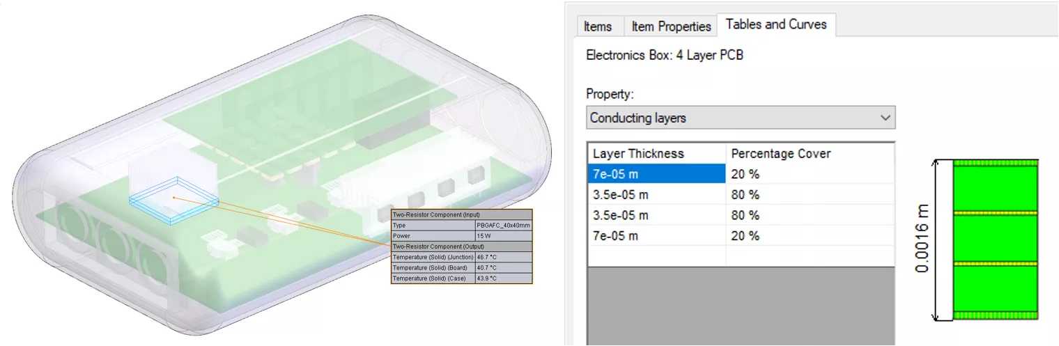
Using the Electronics Cooling add-on package, the study uses an expanded library of materials and components. The PCB Generator allows input of custom board layering to capture conductive heat transfer more accurately through the board. Two-resistor components are also used to simplify the representation of chips on the board.
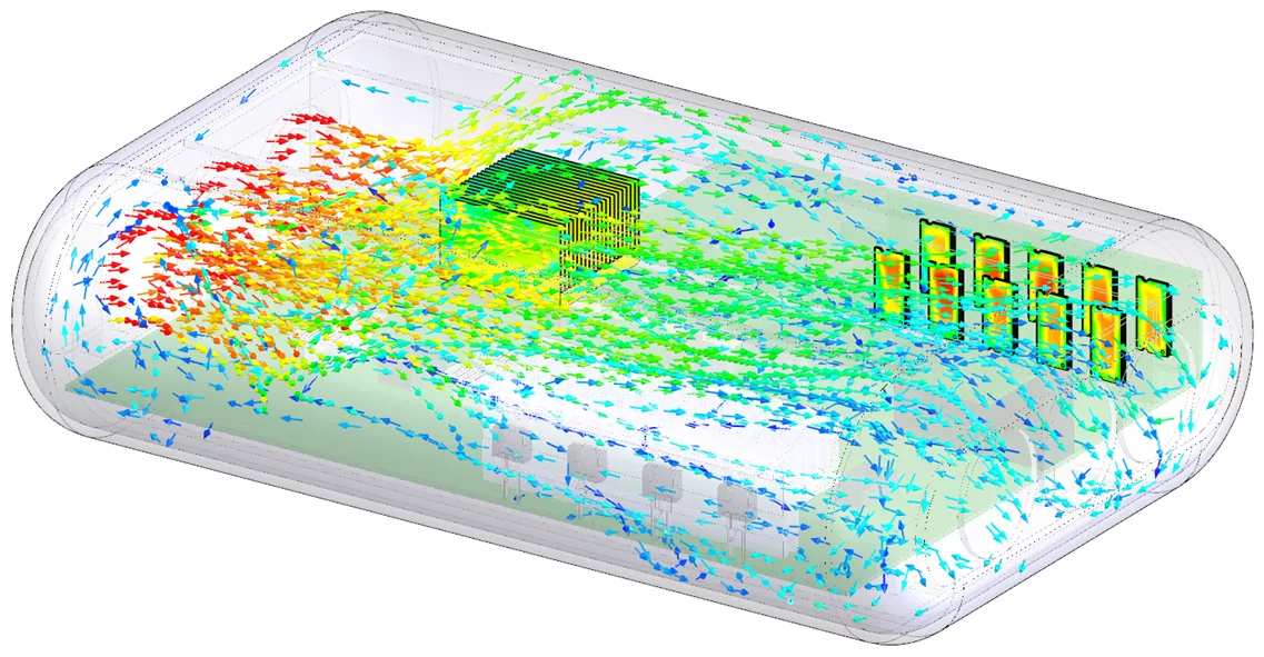
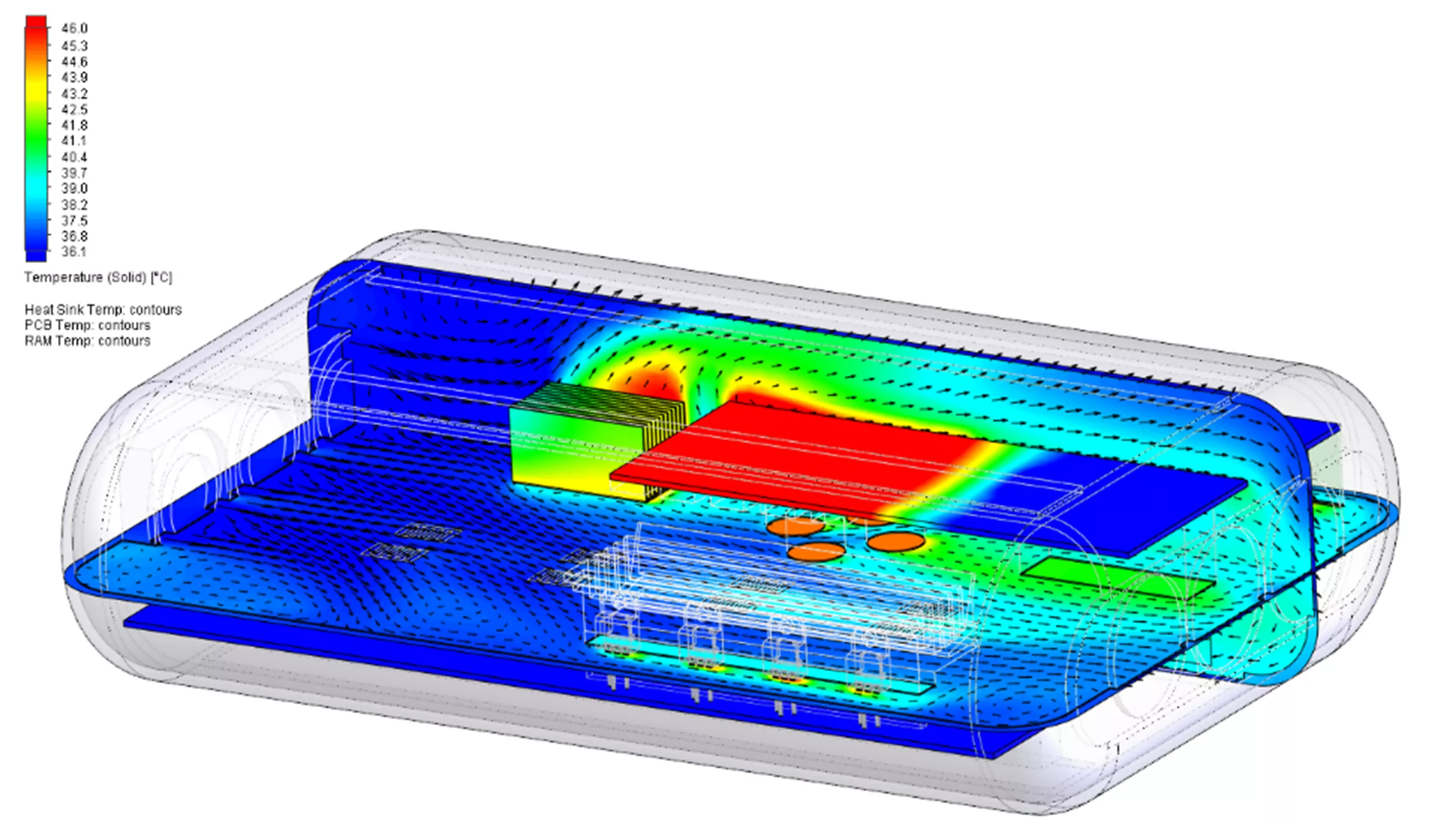
With the inputs defined, we can now let the solver do its work with automated meshing. Solution convergence at critical locations is based on user-specified parameters, called goals, to determine accurate temperatures and velocities. Note that the below contour plot shows the temperature gradient across the flow field with velocity vectors overlaid.
Finally, flow trajectory plots allow us to visualize the overall trends of the flow field. This helps to understand areas of stagnant flow or where the air temperature is getting too hot.
Thermal – Conjugate Heat Transfer
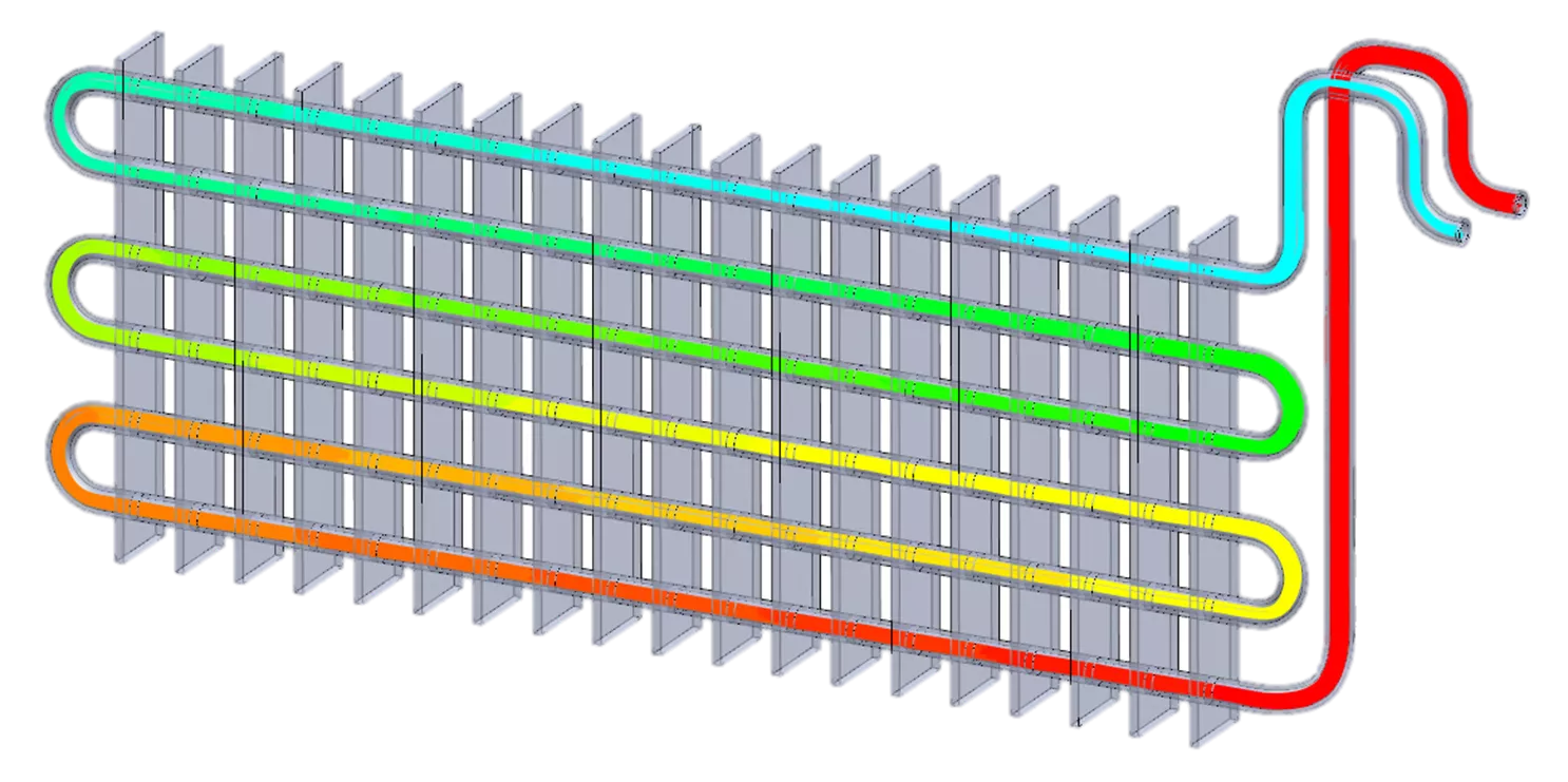
SOLIDWORKS Flow Simulation has so many thermal capabilities that it’s worth occupying two spots in this list. This use case highlights the ability to consider two domains. This two-phase heat exchanger has an internal domain of water, and the external domain is air with a prescribed velocity vector direction to add to the condition of forced convection. Flow Simulation will calculate the cooling performance of the heat exchanger by using a combination of conduction and convection.
Along with the external air velocity, the setup is finished by defining a water flow rate at the inlet and an environmental pressure at the outlet. After that, the study is sent to the solver to quickly calculate the thermal conditions.
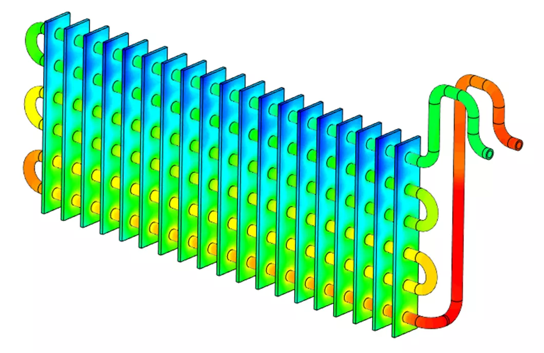
Results show the amount of cooling via conduction on a solid body surface plot (below) and the internal temperature of the water (above).
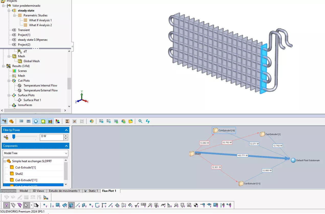
The heat flux plot shows how heat energy is transferred between solid bodies and domains. This example shows the comparative heat transfer between the solid bodies and the water domain as well as the external air. As expected, the plates near the inlet and outlet are losing slightly more heat to the external air because the flow is warmer as it enters the array of cooling plates.
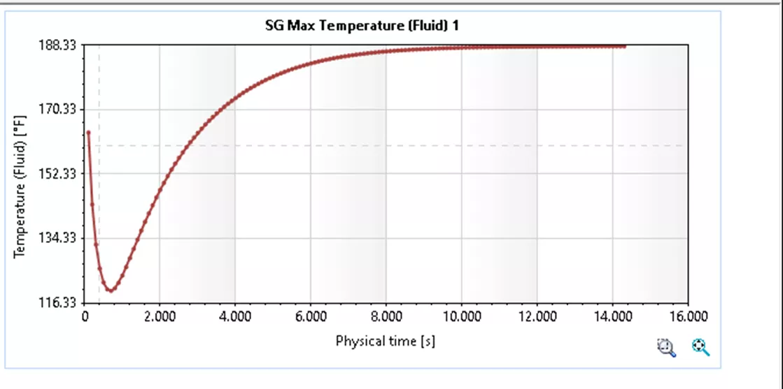
In a transient study, results are observable with respect to real-time. This allows the designer to answer the question “How long does it take for my system to reach a steady state?” and shows the flow field’s development.
The transient solution also lets the user track data over time. Here is an XY plot showing the cooling trend and how quickly it transitions to a steady temperature at the outlet.
When iterating the design, it would be easy to determine the effect of different water flow rates or external air velocities. With the direct integration into the SOLIDWORKS model, understanding the effect of adding more cooling plates to the array would also be very simple.
Pipe Systems – Fluid Flow Through a Valve
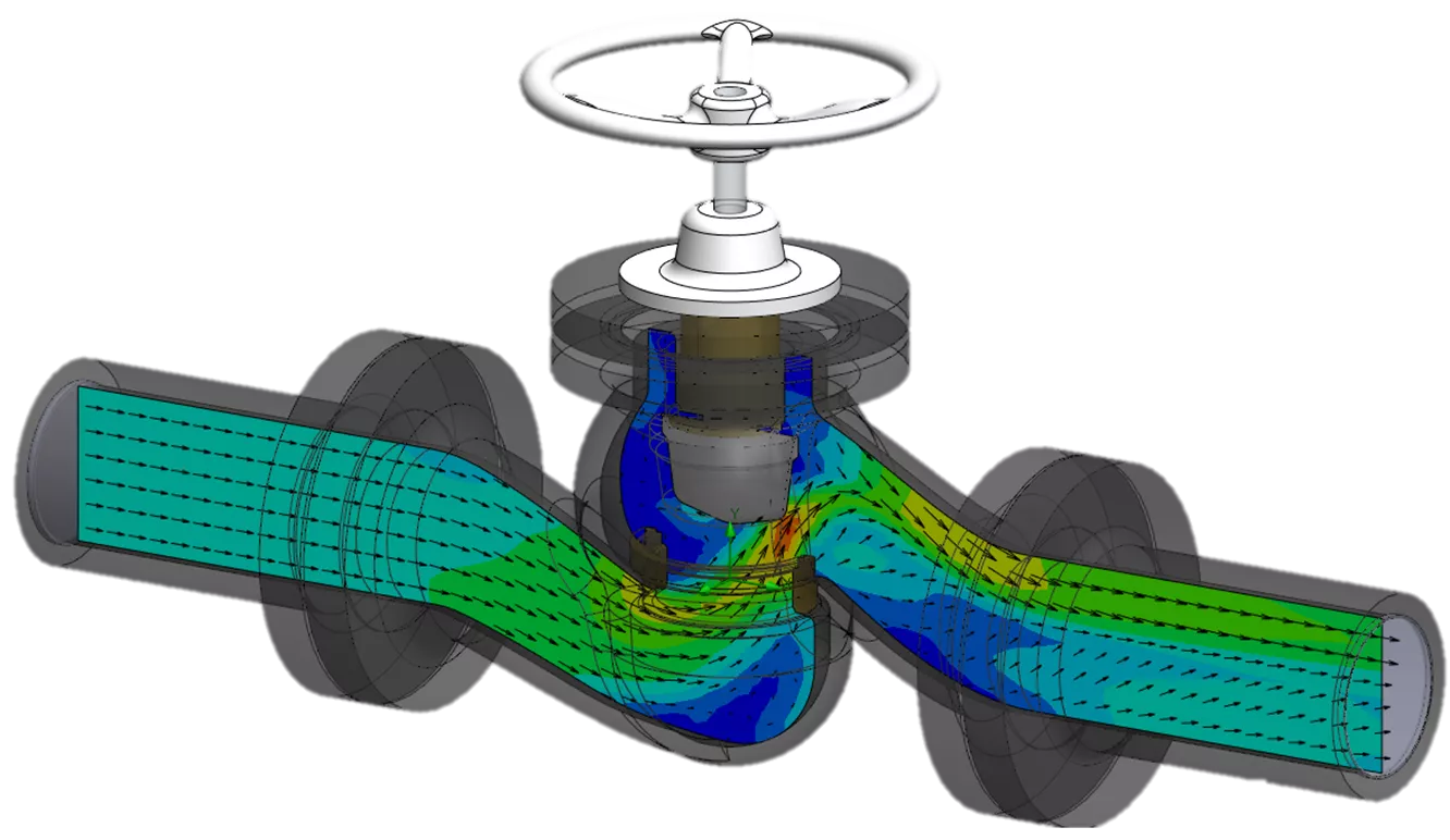
SOLIDWORKS Flow Simulation can handle all kinds of internal flow through pipe systems including valves, manifolds, pumps, impellers, and more. The software can handle any system that carries fluid. This example is a simple scenario where flow will be calculated through a valve.
The study has a flow rate specified at the inlet and an ambient pressure condition at the outlet. The solver will generate an equivalent flow rate at the outlet to follow conservation of energy principles. If there were more than one outlet, the outlet flow rates would equal the flow rate at the inlet.
With the valve only slightly opened, higher velocity flow is clearly observed around the small opening, and the flow becomes very stagnant on the back side of the valve as expected.
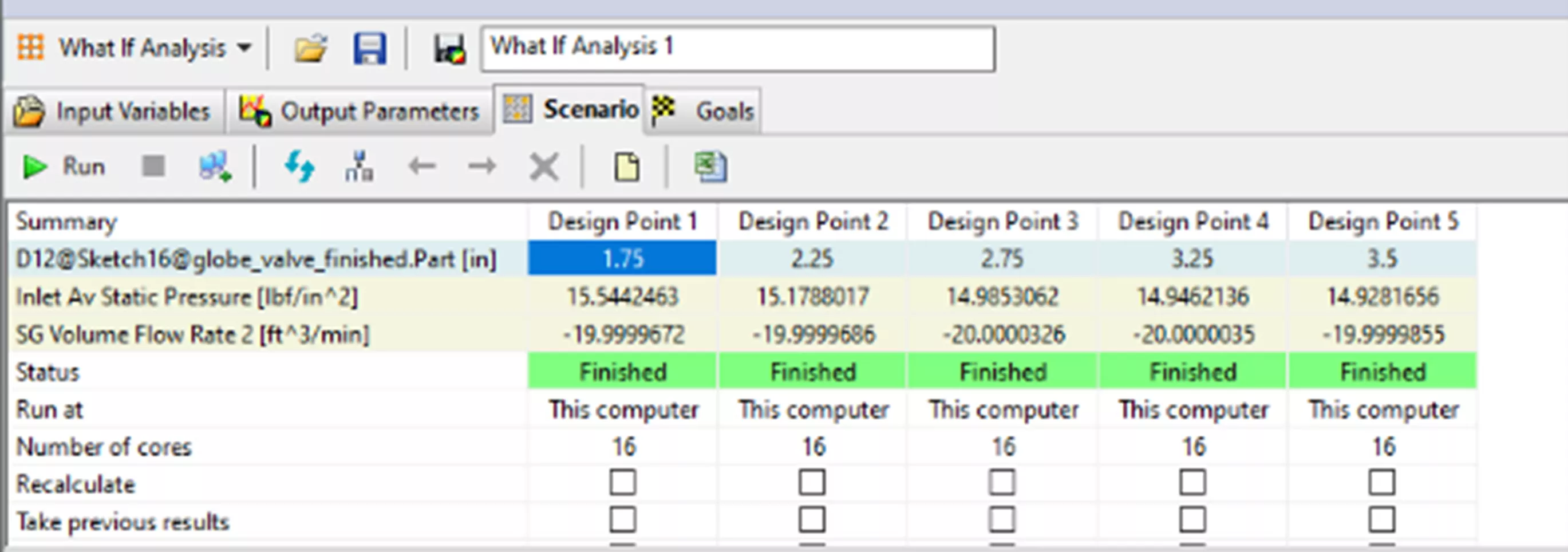
Flow Simulation can also handle parametric studies. These powerful scenario builders allow users to perform a “what if” study, optimize toward a single goal, or even set up a large design of experiments. Each of these parametric studies provides the ability to iterate the design based on some set of variables. The variables can be numerical inputs like design dimensions, pressure, or flow rate.
This valve study will be iterated to see the effect of gradually adjusting how open the valve is by adjusting the mate distance controlling the valve position. The results show that when the valve is about 2.5 inches open, pressure starts to build up at the inlet. If the valve is opened any more than that, there isn’t much effect on the inlet pressure.
Fluid Mixing – Rotating Region in a Mixing Tank
This fluid mixing example will highlight a couple of key functions of Flow Simulation: rotating regions and fluid mixing. The rotating region feature allows the user to specify an RPM on the impeller and cause a swirling effect in the fluid domain.
The tank is initially filled with water, and an inlet is specified with concentrated chemicals. The time-dependent transient solution will show results with respect to real-time, and the user can make decisions about how well the chemicals are mixing into the water.
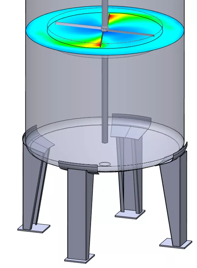
The rotating region is specified with respect to a solid body in the model, and the flow around the impeller is calculated relative to the specified geometry. The image below shows the velocity contour plot at a single time moment.
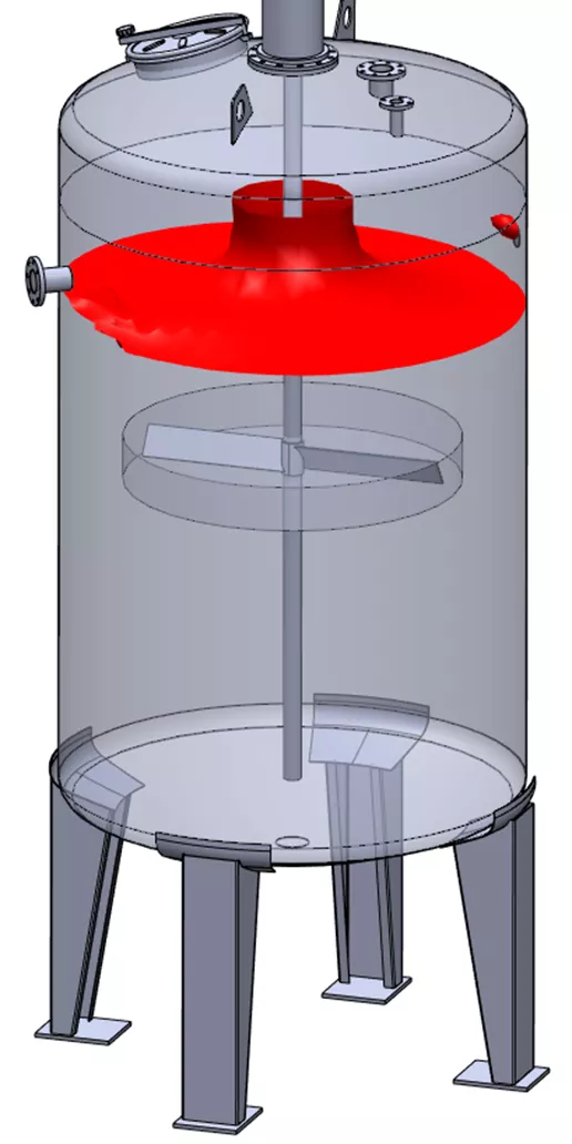
The unique output for this type of mixing analysis is a concentration plot. A useful plot for this situation is an isosurface, which creates a surface where the concentration of chemicals is a certain volume fraction. Here, the swirling vortex is observable by requesting an isosurface where the volume fraction of chemicals is 1%.
The swirling effect is also readily viewable by creating a flow trajectory animation to show where in the domain the chemicals are more concentrated, and where they are more evenly distributed. Designers could choose where to place an outlet based on this type of analysis, for example.
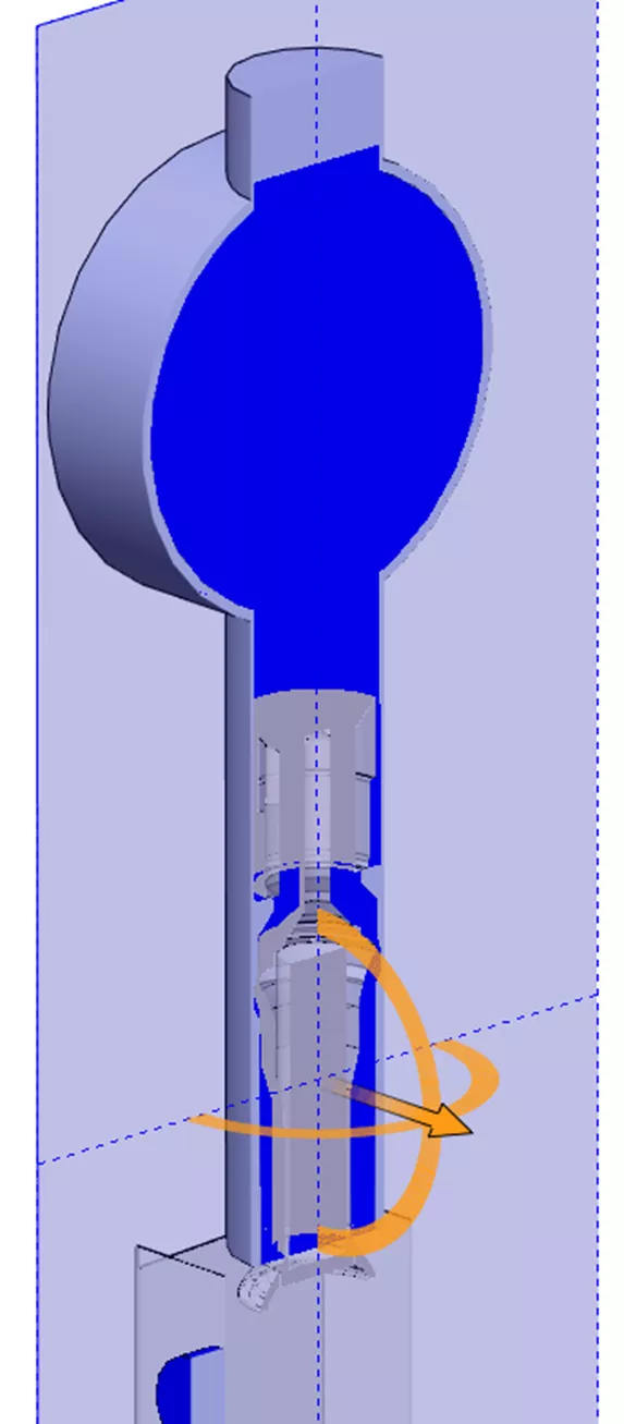
Free Surface – Filling a Carton
The free surface functionality calculates the boundary layer between two immiscible fluids (in this case, water and air) Immiscible just means unable to mix. We know intuitively that air (gas) and water (liquid) will never form a uniform solution when combined. This study type could also consider two immiscible liquids, like oil and water.
The study setup involves defining an initial condition. In this case, the metering bowl is defined as filled with water at the initial time step. The initial configuration of the model is with the valve opened, so as soon as the solver starts, the water will fall into the carton.
With the transient solution, the designer can determine how long the valve needs to be open to fill the carton. After only half a second, the carton is already overflowing and splashing over the sides.
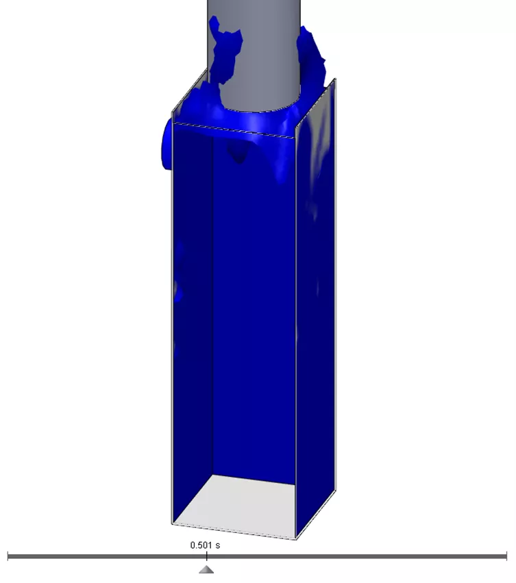
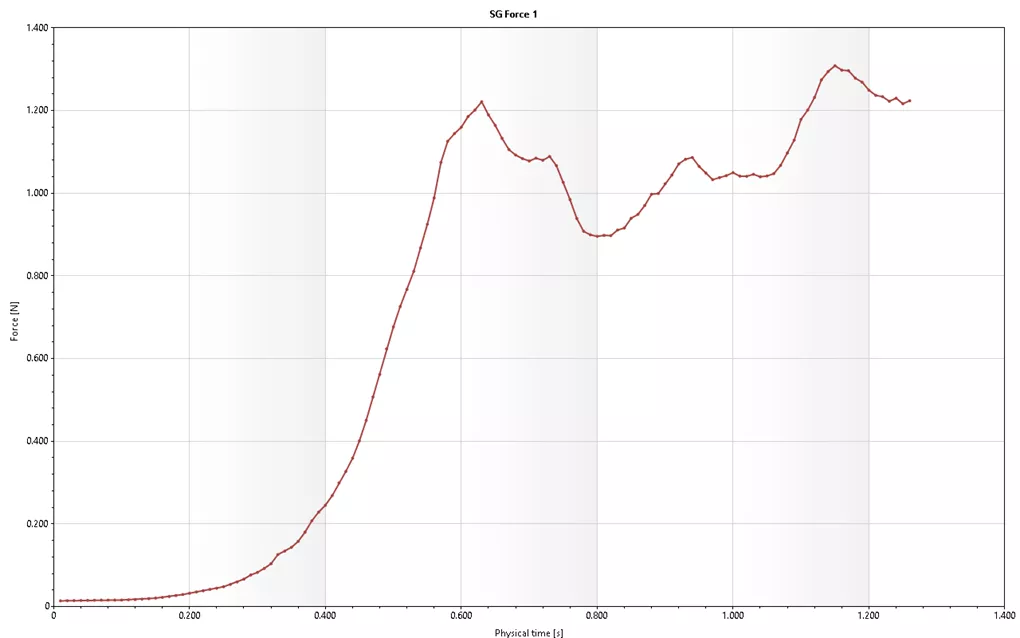
It’s often critical in free surface studies to track the force magnitude on walls due to the fluid splashing and sloshing around. A surface goal can track this information in real-time. This information could be used to determine if the carton will be strong enough or possibly tip over.
Conclusion
These are just five of the more common use cases for SOLIDWORKS Flow Simulation, but there are many more! Contact GoEngineer to discuss your unique fluid simulation scenarios. We can figure out the right solution for you.
Learn More About SOLIDWORKS Flow Simulation
SOLIDWORKS Flow Simulation Results Analysis Tools Explained
SOLIDWORKS Flow Simulation Free Surface and Gravity Dependency
SOLIDWORKS Flow Simulation Carbon Monoxide Flow Tracer
Winter Beehive Analysis Using SOLIDWORKS Flow & Thermal Simulation

About Sam Oanes
Sam Oanes is an Application Engineer at GoEngineer. When Sam isn’t helping customers or teaching SOLIDWORKS classes at GoEngineer, he enjoys running, camping and fishing.
Get our wide array of technical resources delivered right to your inbox.
Unsubscribe at any time.