Structural FEA for Beginners: 5 Stages of Simulation-Driven Design
Simulation, or virtual prototyping, allows engineers to see the performance of their design in ways even lab testing cannot easily do. Even better, it’s often more cost-effective, more timely, and less laborious than everything you have to do to carry out a physical test. Something that valuable must be expensive and hard to implement, right? Not necessarily.
Table of Contents
- Why Simulate?
- Getting Started – Conceptual Design
- First Software Purchase – Preliminary Design
- Cutting-Edge Analysis – Detailed Design
- Summary
GoEngineer has helped thousands of small to large businesses adopt and upgrade their use of analysis tools. In this article, we’ll lay out the distinct stages of simulation utilization that make it very manageable for a design team to grow from novice to expert, as we have seen it happen time and again with our customers when using SOLIDWORKS Simulation and Abaqus-based FEA tools.
Why Simulate?
Before we get into the stages, let’s start with the “why” of it all. Consider a design cycle split into three phases: conceptual, preliminary, and detailed design. Early on, idea generation and changes can happen quickly. However, as a design becomes increasingly precise, complex, and/or interdependent, any change requires far more engineering hours to implement. In the worst case, a product is in the field before a failure condition is noticed. This is why we have simulation: to reduce the cost of change.
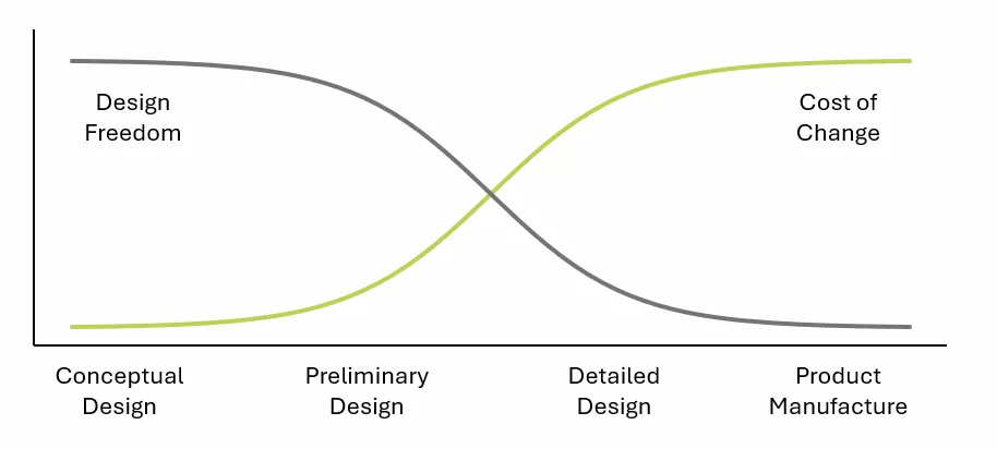
Figure 1: Representative cost of change against design stage
Simulation may also be referred to as “analysis” or “virtual prototyping. A virtual prototype can range in accuracy from “accurate in the specific area of concern” to “generally accurate to any use case of the product”. The very best virtual prototypes may even replace physical prototypes for regulatory or certification purposes.
Industry trends show that top-performing companies are 30% more likely to have in-house virtual prototyping as compared to their competitors. Statistics also show that nearly half of the CAD industry is already taking advantage of virtual prototyping in some capacity (Virtual Prototype Market Size, Grand View Research).
When a product is at the end of its design cycle (for example, a complex assembly employing complex physics), predicting its response requires bigger and better simulation tools. You may think of this when you think about simulation or see simulation marketing.
However, analysis tools are not solely used to exactly predict reality just before a product is manufactured. They are a tool in the engineer’s toolbox, able to be employed throughout the design process. There are much easier (and cheaper!) tools that align with not only the final design phase but also the conceptual and preliminary phases.
If you’re ready to bring virtual prototyping in-house, start from the bottom and work your way up. With the appropriate tools, training, and roadmap, you can predictably reach your end goal through a series of small victories.
Getting Started – Conceptual Design
Every business has different needs, but trends among GoEngineer's clients involve implementing analysis at the conceptual stage and developing it over time into detailed design.
Real life is complex, but the general way a structure reacts is often predictable with pen and paper. Look around your desk, how many objects can be simplified into cylinders and rectangular prisms? In the images below, what is the shear force seen by the bolts when the shaft is under torque?
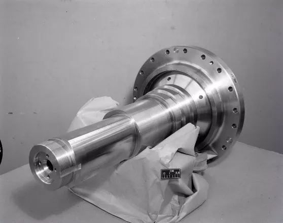
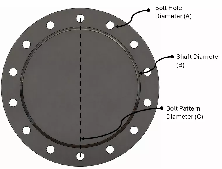
Figure 2: 10 Stage compressor and rig shaft vs. a representative, simplified CAD model
The realistic geometry may inspire questions such as, how do the preload, press-fit, and manufacturing tolerances affect the result? While this is possible to analyze in FEA programs, take a look at the image on the right, where the system is simplified into cylinders. Shear force can be predicted out of standard torque, moment of inertia, and shear equations, and thus design decisions can be made efficiently.
Stage 1: Hand Calc & SOLIDWORKS SimulationXpress
Your current design team is almost definitely already taking advantage of simplification. They will benefit from access to common calculators like Excel and basic training in programming languages like VBA and Python. SOLIDWORKS 3D CAD also includes software tools that can help them. Supplement their efforts by reviewing SOLIDWORKS Simulation Verification Problems and ensuring their access to the free SimulationXpress for introductory (linear static structural) FEA on single components.
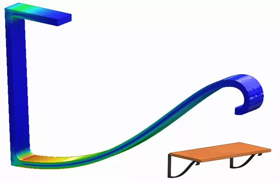
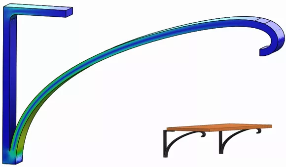
Figure 3: Design comparison using SOLIDWORKS SimulationXpress, analyses shown here had solve times less than 1 minute
SimulationXpress, built into the SOLIDWORKS interface, is immediately helpful for analyzing geometry that is too complex for a quick hand calculation. In the images above, organically shaped iron brackets are compared for stress distributions, maximum deflection, and overall factor of safety. Dimensions and designs are varied using the built-in parametric tool to minimize weight and maximize strength. This visual and numeric feedback is invaluable early in a design.
These tools are easy to start using with little to no training and, of course, no additional cost. Reach out to your SOLIDWORKS VAR if you have questions.
What Stage 1 Success Looks Like
With access to the tutorials and tools mentioned here, and the visual and numerical feedback available with SOLIDWORKS SimulationXpress, your designers will build a stronger foundation in structural mechanics and expand the capabilities of their own hand calculations.
As designers build confidence with structural mechanics and FEA:
- Design time spent discussing and iterating in the conceptual design phase will be shortened.
- Designers will have another method to make stronger, clearer cases for why certain design changes should occur.
- The overall team should see process time improvements for time-critical tasks.
First Software Purchase – Preliminary Design
Eventually, there is enough representative CAD and component interaction in assembly-level design, such that a full FEA tool will be beneficial.
If a majority of your products are made of rigid materials, typically the goal is to focus efforts on avoiding permanent yielding and other failure modes. FEA tools at this level offer these failure mode “analyses in a box” – they are somewhat templatized in order to make it easier for the designer to execute. In addition to predicting final outcomes, these tools, due to their CAD-embedded nature, will naturally allow for quick comparative analysis of design alternatives.
Stage 2: SOLIDWORKS Premium & SOLIDWORKS Simulation Standard
This is your entry to analyzing load-bearing assemblies. Whether you already know the loads to prescribe or must extract them using the included motion analysis tools, this first, feature-complete level of SOLIDWORKS FEA will help you successfully design strength and durability targets.
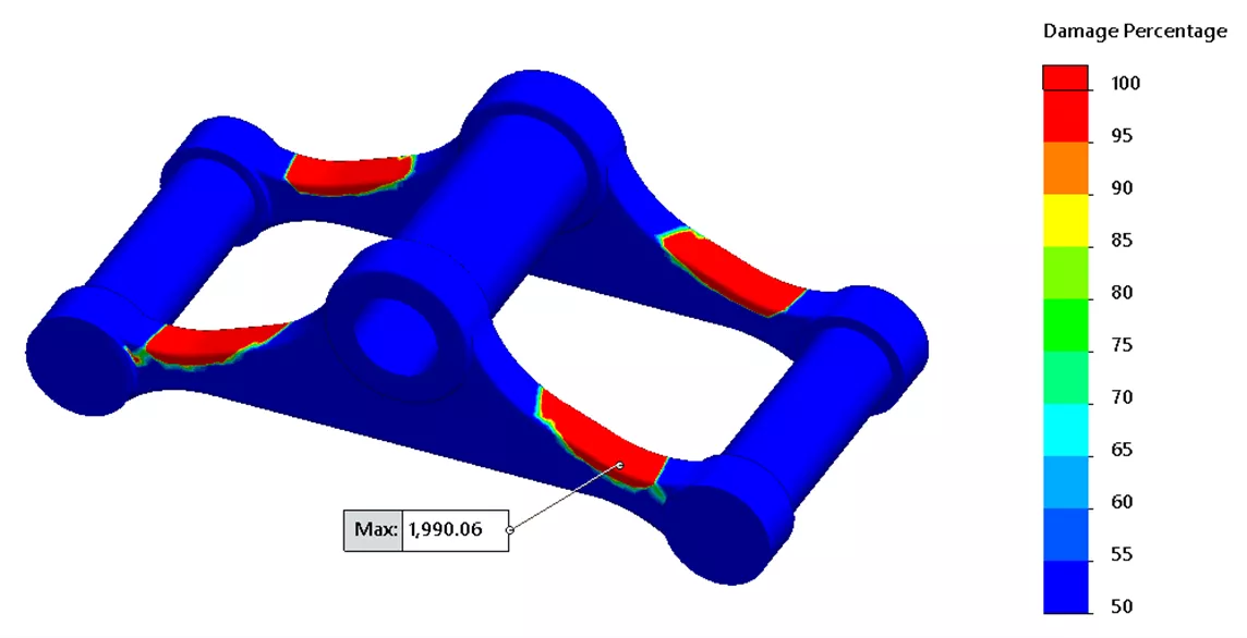
Figure 4: Damage percentage plot from SOLIDWORKS Simulation Standard
If you’ve worked with SimulationXpress before upgrading, everything should feel familiar, but we still recommend some Essentials training, which can be done at your own pace (and includes office hours with a GoEngineer instructor). If you’re a current SOLIDWORKS subscriber with GoEngineer, this course is free! Log into the GoEngineer portal to get started.
Stage 3: SOLIDWORKS Simulation Professional
Many companies know from the jump that they need a little more than linear static analysis. With the user experience across all SOLIDWORKS products being so similar, it’s just as easy for them to start at SOLIDWORKS Simulation Professional. This next tier lets you predict additional failure modes, like natural frequency, buckling, or fatigue. I’ll use an example of a tank under a pressure load to illustrate.
The image below is a divided metal tank, one side which will have vacuum pulled. Does the tank divider permanently deform under the atmospheric pressure load? What size welds should be used to keep the divider in place? Linear static analysis calculates displacements, stresses, and reaction loads for rigid materials under the effect of constant, steady loads. This type of analysis would provide visual and numerical feedback to answer those questions.
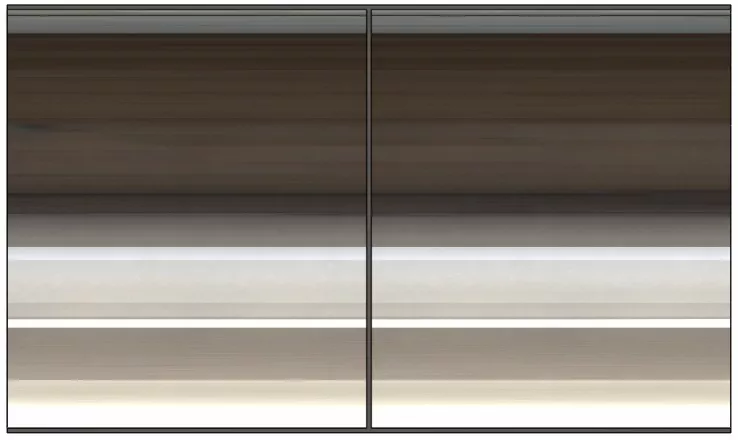
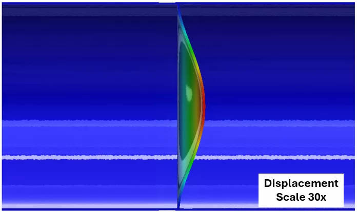
Figure 5: Tank with 14psi applied to tank divider. Deflection results from a linear static analysis shown at 30x scale.
A long thin plate such as this may buckle when vacuum is pulled on one side. In the field, this may appear as the plate bowing slightly while more air is pumped out of one half of the tank, however, after a certain amount of air is removed, the divider will suddenly ‘pop’, and a great amount of deflection will occur. Rather than predicting exactly how the plate will buckle, let’s avoid buckling altogether by predicting at what pressure load buckling is likely to occur.
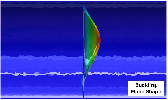
Figure 6: Linear Static displacement results (left) and linear buckling mode prediction (right). Simulation supplies at what critical load buckling is likely to occur
Additional gussets could reduce initial deflection and prevent buckling. Create gusset configurations, reuse previously set up analyses, and batch run many analyses in an optimization series to efficiently compare design ideas and get strong design insights towards the safest design.
Stage 4: SOLIDWORKS Simulation Premium
SOLIDWORKS Simulation Premium expands virtual testing capabilities into linear and nonlinear dynamics – shock, cyclic, random vibration, and peak-response style loading. In terms of materials, SOLIDWORKS Simulation Premium static analyses can reflect plastic deformation and hyperelastic behavior. The Premium tier also allows for more complex load combinations or sequencing. You can learn more in our article dissecting the various tiers of SOLIDWORKS Simulation.
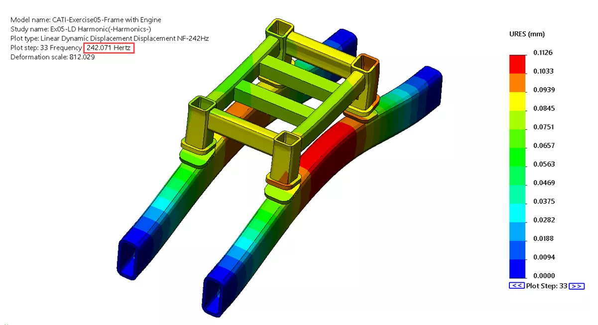
Figure 7: Reviewing displacement plots at certain frequencies
3DEXPERIENCE Alternatives to SOLIDWORKS Simulation
There is a first-party cloud/SaaS alternative to SOLIDWORKS Simulation available on the 3DEXPERIENCE Platform. The two lower tiers of the 3DEXPERIENCE STRUCTURAL FEA tools are roughly equivalent to SOLIDWORKS Simulation Professional and Premium. While the interface and FEA solver are different (3DEXPERIENCE STRUCTURAL takes after Abaqus), it remains connected to your native CAD.
You may wish to opt for 3DEXPERIENCE if you: are using the 3DEXPERIENCE version of SOLIDWORKS, want to leverage cloud compute, or plan to eventually scale up to the most advanced kinds of simulation.
Hardware & Training for SOLIDWORKS Simulation
To use a CAD-embedded FEA program like SOLIDWORKS Simulation, a designer will also need access to a SOLIDWORKS license and a PC capable of running SOLIDWORKS. It is not necessary to upgrade a PC that is already running SOLIDWORKS in order to then run SOLIDWORKS Simulation. Visit our hardware guide to review what PCs GoEngineer and our partner Dell recommend for SOLIDWORKS and SOLIDWORKS Simulation.
For 3DEXPERIENCE STRUCTURAL, FEA compute can be done on-cloud. Once again, the CAD workstation will be fine, but local resources won’t be needed for running the simulation (unless, for some reason, you want to – the option is available).
Bringing CAD-embedded virtual prototyping in-house will involve training on user interface, FEA theory, and access to more experienced analysts to avoid pitfalls and obtain guidance on applying FEA to your particular products.
Training on user interface and building a stronger structural mechanics foundation typically takes one to four weeks, depending on the method of training chosen. Increased confidence comes when a team emulates a previous design or lab test, or finally reaches the physical prototyping stage and can compare back to their FEA tests. Typically this comparison will occur at the macro scale (for example, maximum displacement overall) or could aim for percentage bands (for example, virtual test response consistently 5% above physical test response). Depending on the data available, this can take anywhere from a few days to the length of a full design cycle.
GoEngineer offers support at all of these stages, from standardized self-paced training, customized in-person training, or on-demand one-on-one support with our experts.
What Stage 2-4 Success Looks Like
At the SOLIDWORKS Simulation Standard tier, access to structural analysis will answer, “Which design is better?” or, “Is this the right direction to go?”.
As you move up the stack into Professional and Premium, with the ability to predict failure modes due to various physics, you can more strongly answer, “Will my design fail”? Removing a majority of that danger in the preliminary phase will remove time spent iterating failures experienced during physical prototyping. This has three significant impacts:
- It reduces the budget spent on manufacturing prototypes so it can be spent elsewhere.
- It reduces time spent manufacturing prototypes so products can get to market faster and engineers can devote their productivity to other projects.
- It makes engineering easier – earlier in the development phase, you will have more freedom to make the necessary corrective changes. (Figure 1)
Cutting-Edge Analysis – Detailed Design
When a design becomes sufficiently mature and complex, the next step is to look into a more powerful FEA program capable of higher fidelity, increased model scale, and multiphysics scenarios. Such tools can still be CAD-associated and work for a designer, but if the workload is high enough (for example, if multiple teams are adopting simulation in parallel or the product assemblies are extremely large), hiring a dedicated analyst may be wise.
To embark on this phase, a design house should determine what specific physics are critical to their response prediction. The specifics of either your product assembly or the use case scenario you are trying to create may begin to exceed the more “fill in the blanks” simulation setup templates of SOLIDWORKS Simulation. The physics may also go beyond the capabilities of the previous FEA tool, particularly in material behavior or deformation or component interactions.
For instance, a gasket manufacturer may be interested in the nonlinear response of a specific rubber when compressed and pressurized. A bottle manufacturer may wish to determine what changes must be made to their assembly line to prevent the cracking of glass bottles under load cases such as pressurization, liquid-solid mechanics during transport, or incident vibrations. A Dassault Systèmes VAR with simulation experience (such as GoEngineer, as we have a dedicated CAE consulting team) can help you determine what simulations can (and should) be done, using what tools, by what methodologies, and with what validation.
Figure 8: Frequency mode prediction (left), stress response using linear dynamics (middle), displacement response including nonlinear contact using explicit dynamics (right)
Stage 5: 3DEXPERIENCE STRUCTURAL Performance Engineer, Structural Mechanics Engineer, and Abaqus
Whatever you’re trying to simulate in the structural realm, the upper tiers of 3DEXPERIENCE STRUCTURAL (Structural Performance Engineer & Structural Mechanics Engineer), and the traditional Abaqus solver on which they are based, can handle it. You can learn more about the crossover from SOLIDWORKS to Abaqus in our article on the topic. Your SOLIDWORKS VAR should be able to discuss the differences between traditional Abaqus and high-tier 3DEXPERIENCE STRUCTURAL as they pertain to you – those differences have much to do with user experience and fringe capabilities.
Hardware & Training for the Abaqus-Based FEA Tools
As for hardware to power these advanced structural FEA tools, while getting into high-performance computing (HPC) may make sense for large teams, as an individual designer, a powerful CAD workstation is probably enough. 3DEXPERIENCE STRUCTURAL products include a modest amount of cloud compute access, and for the occasional extra-large analysis, additional capacity can be rented (up to 192-core compute).
Transitioning from a SOLIDWORKS FEA tool to 3DEXPERIENCE or Abaqus would, again, benefit from training on user interface, FEA theory, and access to more experienced analysts, all of which GoEngineer continues to offer.
Wise first steps might be to replicate a previous experimental test or have us alongside you as your team goes from advanced analysis to physical prototyping for the first time.
A simulation consulting team (like GoEngineer’s) can even work with a company to match physical test data and develop an analysis methodology. They can then train the company on that methodology (or any other FEA topic that would be helpful) to bring that Abaqus-based simulation in-house.
Alternatives to Adopting Stage 5 Simulation
Some companies have infrequent need for extremely large or advanced simulation, but would greatly benefit any time they do leverage it. In such cases, simulation consulting on a per-project basis may be the solution. GoEngineer’s Simulation Services team provides project analysis and product development services, where they can step in for particular use-cases or projects when there isn’t the time or budget to develop such capabilities in-house.
Figure 9: Full-vehicle impact, dynamic explicit simulation
What Stage 5 Success Looks Like
As products become more difficult and costly to physically manufacture and test, it becomes increasingly more valuable to use high-end simulation to digitize testing till as late in development as possible. Effective use of advanced simulation will reduce testing costs and increase success with challenging engineering while staying competitive in the market.
The most advanced simulation tools are a blank slate. Powerful solvers with no guard rails let you do just about anything, so it becomes a matter of strong background knowledge, creativity, and ambition. The skill ceiling is infinite – it’s just a matter of time and experience to extract more value out of time spent simulating.
Summary
Bring virtual prototyping in-house by deciding when in the design cycle your team would best benefit from virtual prototyping, and then find the tools to match.
- Begin with SimulationXpress and SOLIDWORKS Simulation Validation examples – apply them to conceptual design.
- Build a foundation in hand calculations and FEA theory. Get quick, easy answers for no cost.
- Contact SOLIDWORKS support if you need help.
- Purchase a CAD-embedded preliminary design tool from the SOLIDWORKS Simulation portfolio for quick, iterative testing and failure mode avoidance.
- These tools give you relatively pre-structured analyses to improve your product designs.
- As a GoEngineer customer, your Elite Success Plan gives you access to unlimited self-paced simulation training courses in simulation (which include office hours!).
- As you improve with the tool and start seeing value, upgrade the software through the three tiers (or their 3DEXPERIENCE equivalents) to predict more aspects of your product’s performance.
- For increasingly detailed design, move into high-end FEA with the higher tiers of 3DEXPERIENCE STRUCTURAL, traditional Abaqus, or simulation consulting.
- If you have been working up sequentially from more introductory FEA tools, you will now have a good understanding of how FEA works, where the pitfalls are, and what you would like to understand better about your product’s performance.
- In the early days, it can be extremely helpful to work with GoEngineer’s simulation consultants to develop the FEA methodologies that make the predictions you need. Standard (and even custom) training courses continue to be helpful.
- The tools can do just about anything at this point, so going forward, it’s all about gaining and exploiting lessons from experience. Set incrementally higher goals for simulation and work to achieve them.
Supplement any investment with support from a partner like GoEngineer. GoEngineer offers training courses in the form of self-paced, online, or in-classroom.
Build trust in virtual prototyping by comparing analyses against experimental or field results. GoEngineer is here to help you through this process. Application mentoring sessions, enhanced support, custom training courses, or FEA/CFD services for hire are common methods of connecting our technical experts to yours in order to transition from understanding the program to applying it.
Wherever you are in your journey with analysis, get to know your simulation software or services provider. The resources they offer can help you achieve your product development goals.
SIMULATION IS IMPORTANT.
It’s common knowledge that simulation helps us design faster, better, and at lower cost… but knowing and doing are two different things. Learn more with our Smarter with Simulation campaign.


About Shivani Patel
Shivani has a background in aerospace engineering, and is the Engineering Manager for southern Texas. She has the Elite certification in SOLIDWORKS and is happy to jump into anything in the SOLIDWORKS licenses. Her main specialty is Simulation - and has spent the past 6 years digging into the Motion Analysis, FEA and CFD programs and supporting many of our oil and gas customers in the south.
Get our wide array of technical resources delivered right to your inbox.
Unsubscribe at any time.