SOLIDWORKS Weldment Sketch From Solid Model Tutorial
While many users leverage weldments inside of SOLIDWORKS, one of the main challenges is the creation of 3D sketches needed for the layout of structural members. In this tutorial, learn how to use a solid model in SOLIDWORKS to generate and parametrically drive 3D sketches, foregoing the hassle of creating them manually.
- Suggested Reading >> SOLIDWORKS Weldment Profiles & Weldment Tools Guide
Traditional SOLIDWORKS Weldment Setup
Typically, when creating weldments in SOLIDWORKS, there can be multiple 3D sketches needed to lay out the paths for structural members. It can be challenging to maintain design intent when working with multiple 3D sketches that have relationships to each other.
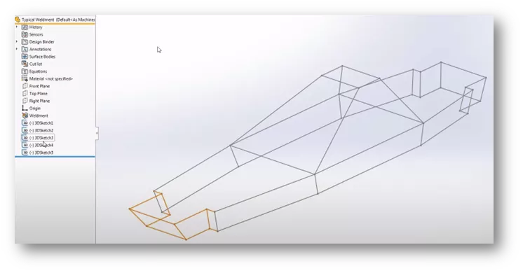
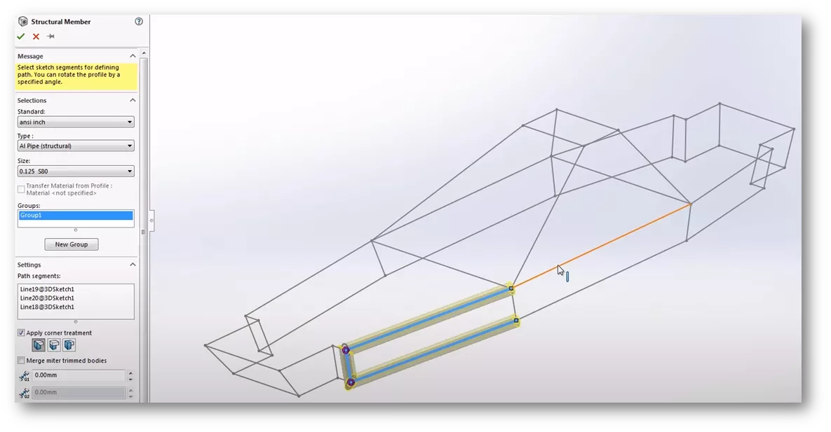
The usual process is, once the layout sketch is complete, to add a structural member and create groups by selecting individual sketch entities.
Solid Model Approach
Now that we have seen the traditional method of creating weldment sketches, we will show how to create them using a solid model. Here we have a solid model representation of the 3D sketch layout. This was created from three 2D sketches on different parallel planes. Sketches were then lofted together.
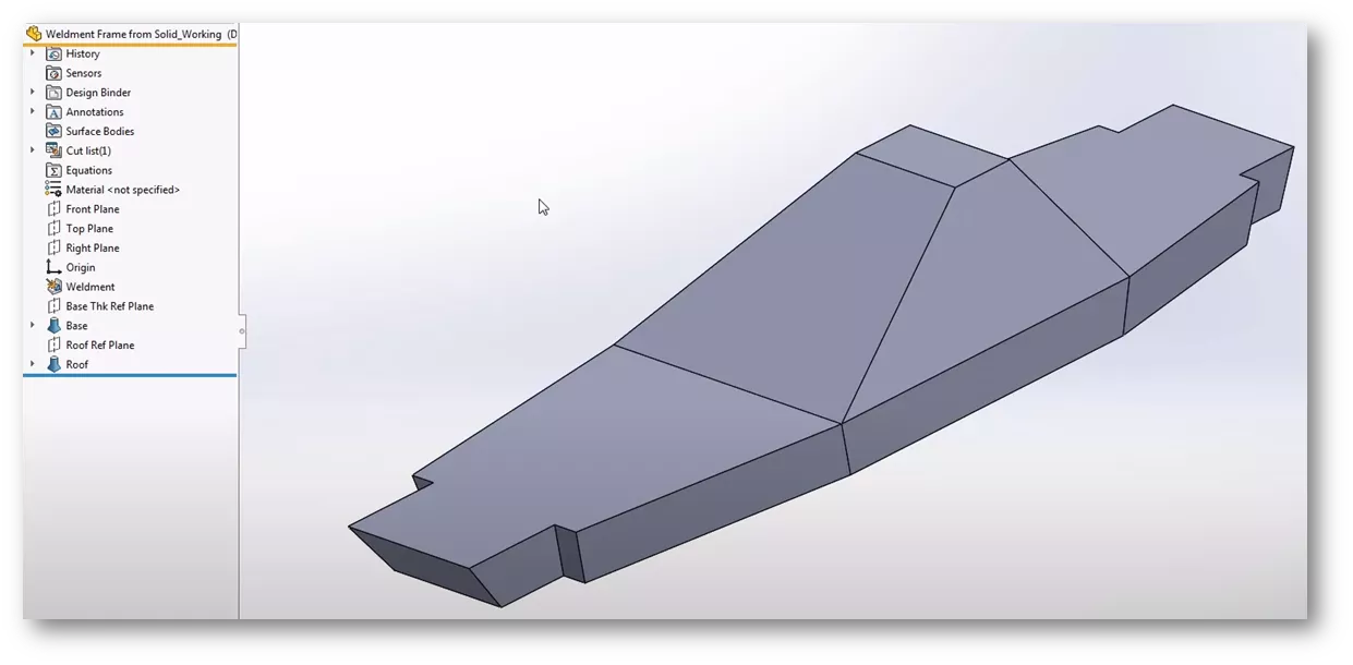
The edges of the solid represent the paths for our structural members, so we will convert them into a single 3D Sketch.
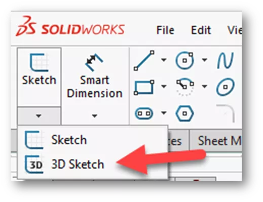
Start a 3D Sketch by going to Sketch Toolbar > Sketch Flyout Menu > click 3D Sketch.
Since we will need to select all the edges of the solid, turn on the Selection Filter and enable the Edge Filter.
Hit F5 on the keyboard to turn on the Selection Filter Toolbar. Click Edge Filter.

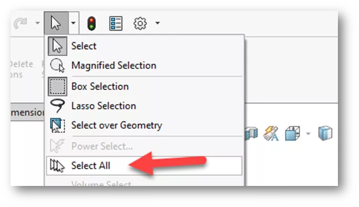
Now we need to select all edges. Since we enabled the edge selection filter, we can perform a Select All to capture all the edges simultaneously via Standard Toolbar > Select Flyout Menu > Select All.
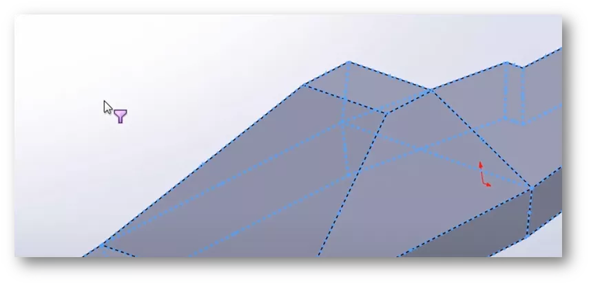
Now that all the edges are selected, the next step is to convert them to sketch entities. We will do this with a tool called Convert Entities.
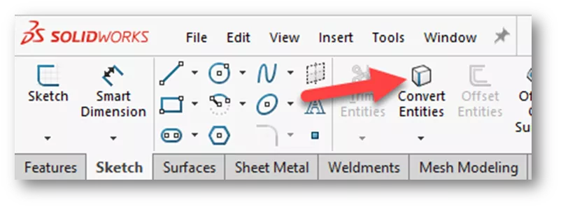
Sketch Toolbar > click Convert Entities.
- Suggested Reading >> SOLIDWORKS Convert Entities Quick Tips
Once we have converted the edges, the result is a single 3D sketch parametrically driven by the edges of the solid model.
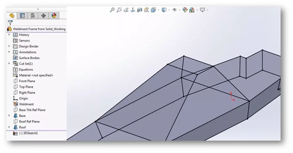
The next step is to add a structural member and select the sketch entities as normal for a weldment. For this example, I have created a base bottom sketch with dimensions to help with creating the solid model. Dimensions can be changed, and the weldment will update accordingly.
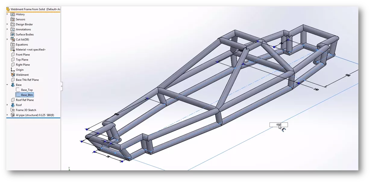
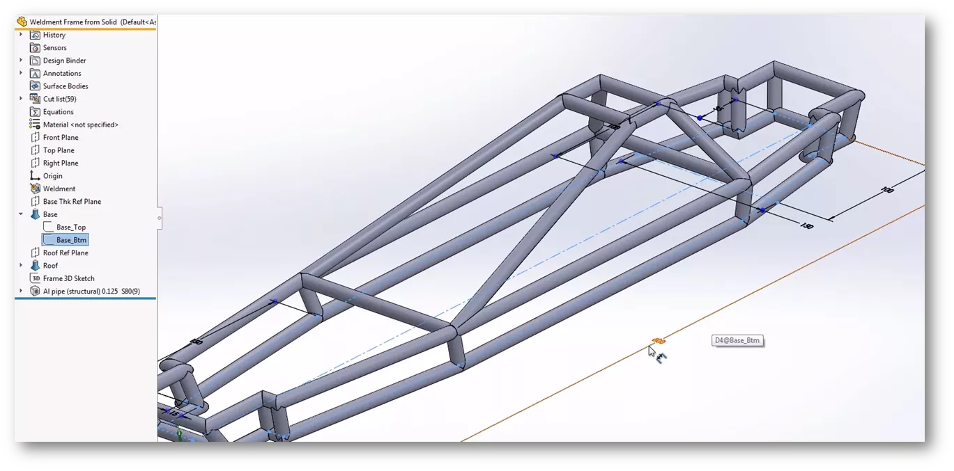
As you can see, the solid model approach to weldment sketches can save time and help with maintaining design intent. I hope you found this tutorial helpful. Check out more SOLIDWORKS tips and tricks below.
![]() Want to learn more? Check out this YouTube video for a demonstration of these tips, tricks, and best practices.
Want to learn more? Check out this YouTube video for a demonstration of these tips, tricks, and best practices.
SOLIDWORKS Weldment Training
Learn to build stand-alone sheet metal parts and create standard structural members by enrolling in professional SOLIDWORKS Weldment training with GoEngineer. Learn more below.
More SOLIDWORKS Tutorials
SOLIDWORKS - Weldment Configurations
SOLIDWORKS 2020 Structure Systems for Weldments
Designing a Trailer Using SOLIDWORKS Weldments
SOLIDWORKS Weldment Profiles & Weldment Tools Guide

About Zach Brown
Zach Brown is a certified SOLIDWORKS Expert and a Technical Support Engineer. Prior to working at GoEngineer, he spent 15 years as a mechanical designer, CAD support tech, and instructor using SOLIDWORKS. His hobbies include playing guitar, riding motorcycles, and skiing.
Get our wide array of technical resources delivered right to your inbox.
Unsubscribe at any time.
