SOLIDWORKS Basics: Crossing the Bridge From 2D to 3D
Many companies have a long history in 2D data, from AutoCAD all the way back to the drawing board. SOLIDWORKS is for some, their first experience in a 3D CAD environment. New users may be wondering what files should be used, when those files should be used, and when should they be doing what. In this article, we'll go over some SOLIDWORKS basics - let's start with terminology.
Coming from a 2D world the term "Drawing" is used for everything, but in SOLIDWORKS it is used for a specific file type. The "Drawing" is used as the deliverable, the piece of paper that your organization would supply to the shop floor or the final data you would send to a customer. Using 2D terminology, this could be the "Part Drawing" or the "Assembly Drawing.

File Procedure
The “Part” file is the individual component. This is the file that your designer is responsible for creating from “scratch”; you can look at this as the “nuts and bolts” of your final, completed design. If a customer were to ask you to design a table, the “Part” would be the individual tabletop, the leg, table supports, brackets, and yes, the nuts and bolts. SOLIDWORKS is a “Part” driven system so it is important to start with “Part” files first.
The “Assembly” file is a make-up of “Part” files. Once the designer has created the individual components, the tabletop, the leg, table supports, brackets, and yes, the nuts and bolts, they will then insert those “Part” files into the “Assembly” file. Then, within the “Assembly” file, your designer will position these pieces to form the actual table.
Now the designer is ready to create the “Drawing” files of the individual “Part” files and the “Assembly” file. It is in this document that the designer will display the 2D Standard three views, such as Front, Top, Right. This document will also contain the Isometric, section, detail, and auxiliary view. Here is when we see title blocks, tables, and notes pertaining to your geometry relevant to your shop floor.
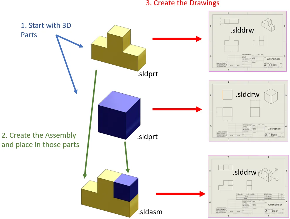
Part files: *.sldprt
Assembly Files: *.sldasm
Drawing Files: *.slddrw
Planes
Planes are flat and infinite pieces of geometry. Inside of SOLIDWORKS, they are displayed with a boarder. However, this displayed border is not your work area. Your work area is the size of your plane, infinite. Each part and assembly start off with three plans, but each file can contain an infinite number of planes if the designer creates them.
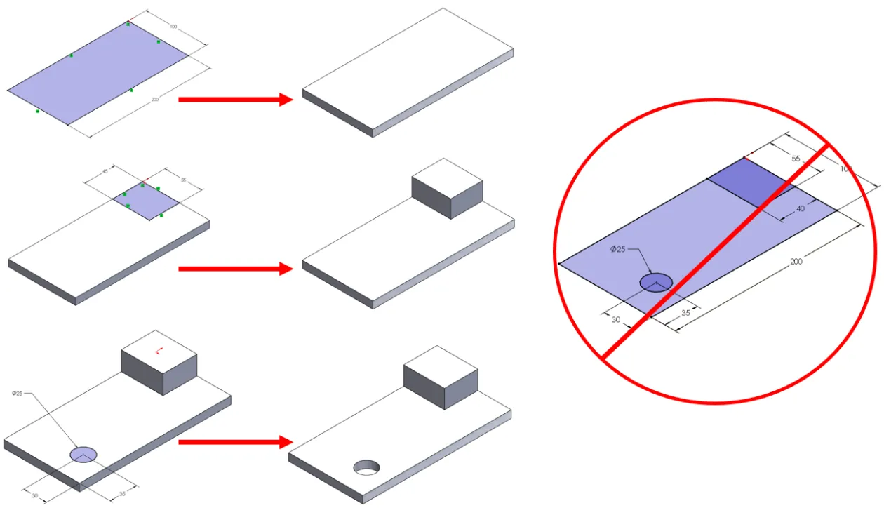
Sketches
Even though SOLIDWORKS claims to be a 3D modeling system, which it is, it is still 2D based. The designer is still responsible for creating 2-dimensional sketches to represent the 3D part. The designer is not sketching views, they are creating “Features”. Features are used individually to create the part.
I hope you found this introductory lesson to SOLIDWORKS helpful. For more tips and tricks, check out the related articles below.
Related Articles
4 SOLIDWORKS Part Modeling Tools that are Time-Savers

About James Ortiz
James Ortiz joined the VAR community in 1997 with DASI Solutions (now GoEngineer) as the SOLIDWORKS Technical Support Manager for Michigan, Ohio, Indiana, and northern Kentucky. James then joined the pre/post-sales team to perform product demos, SOLIDWORKS and PDM implementations, and produce a multitude of content for events and trade shows. James is currently a SOLIDWORKS Training Specialist based out of Auburn Hills, MI.
Get our wide array of technical resources delivered right to your inbox.
Unsubscribe at any time.