How to Adjust Template Settings in SOLIDWORKS
Template files for parts, assemblies, and drawings are the storage location for default
environmental settings used when creating new files. These control the items such as unit
systems, drafting standards, first/third projection angles of drawings, dimension formatting,
annotation formatting, image quality of parts, and many more options.
The template files themselves act only as the initial conditions of a new file. Once a new file is
created based off of a template the new file is no longer controlled or affected by changes made
to the template. So, it is generally a good idea to setup document templates as a first step and to
revisit templates with updates at the outset of new projects.
What settings are encompassed in a template?
There are common locations where template settings are held for all part, assembly, and drawing
templates. All of these locations are listed below.
Part:
Document Properties (found under ‘Tools’, ‘Options’, ‘Document Properties’)
Item Visibility Settings (found under the ‘View’ menu)
Features/Sketches (found in the ‘FeatureManager Design Tree’)
Assembly:
Document Properties (found under ‘Tools’, ‘Options’, ‘Document Properties’)
Item Visibility Settings (found under the ‘View’ menu)
Features/Sketches (found in the ‘FeatureManager Design Tree’)
Drawing:
Document Properties (found under ‘Tools’, ‘Options’, ‘Document Properties’)
Item Visibility Settings (found under the ‘View’ menu)
Sheet Properties (found by right clicking the drawing sheet & going to ‘Properties’)
Sketch entities
Sheet Format (the line art for a drawing title block and border)
The ‘Document Properties’ will hold different settings for part/assembly, and drawing files based
on the specific needs of those modes. Drawing templates, additionally, have template settings
stored under ‘Sheet Properties’.
Please note that the sheet format (title block line art) is not specifcally part of the drawing
template but is stored in a separate “Sheet Format” file that is picked upon creation of a new
drawing. This will be discussed more later in this document.
What do these settings areas look like?
The “Document Properties” dialog will only be available when a document (Part, Asssembly, or
Drawing) is open within SolidWorks. It can be accessed via ‘Tools’, ‘Options’ on the tab of thes ame name. All options found within this tab are settings that can be setup for document
templates and is shown in Figure 1.
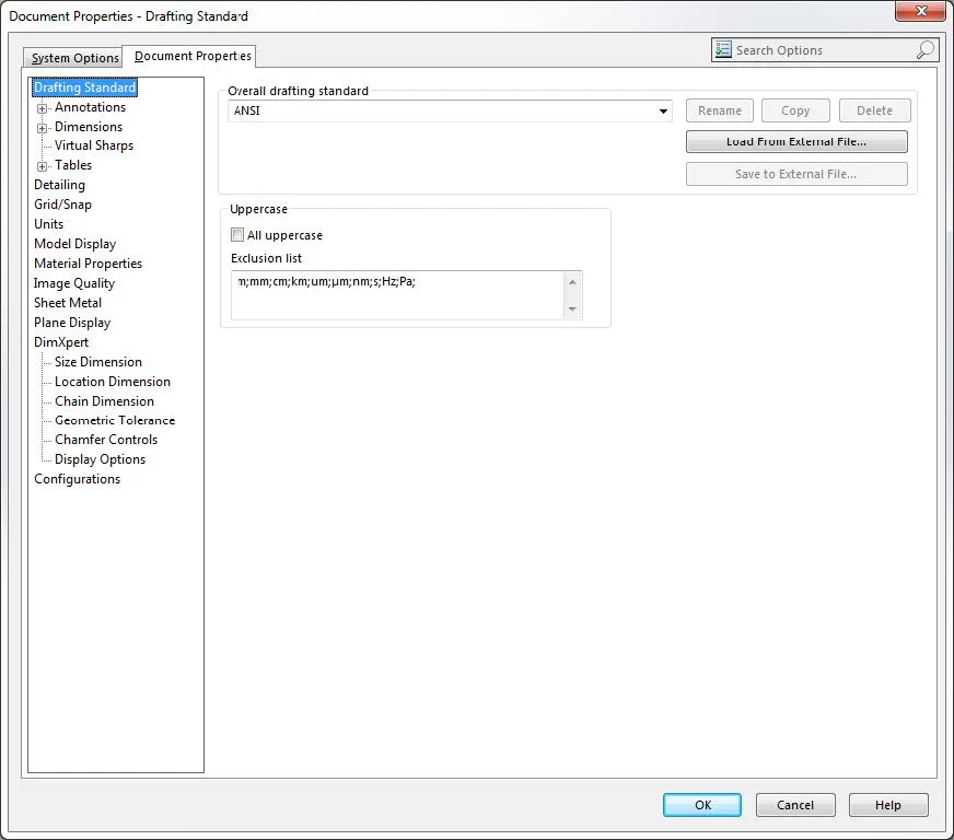
Figure 1: “Document Properties” dialog box.
The “Sheet Format” consists of the backdrop on which all the title block, border line art, title block
properties, and the sheet size of a drawing exist. These are the only items that are stored in a
“Sheet Format” file. If a drawing template is saved with a “Sheet Format” selected that drawing
template will always open with that “Sheet Format” present and will not prompt the user to select
a “Sheet Format” to then apply upon open.
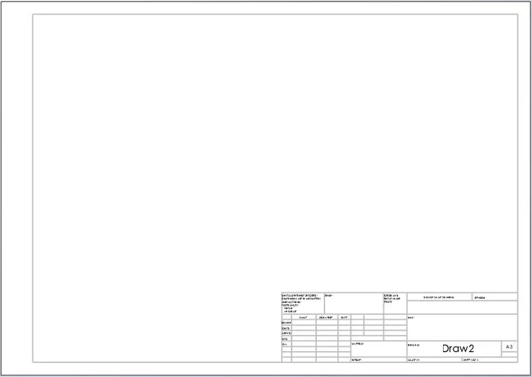
Figure 2: A “Sheet Format” showing title block, border line art.
The “View” menu is found at the top of the SOLIDWORKS Window at all times but will only have
template specific settings once a document is opened as is shown in Figure 3.
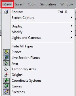
Figure 3: The document specific “View” menu as seen from within a part or assembly file.
“FeatureManager Design Tree” items such as sketches, features, or planes can be put into position
and then saved to be a portion of a part or assembly template. When such templates are then
used to create parts these items populate the “FeatureManager Design Tree” upon creation of the
new file as shown in Figure 4. Additionally, sketch entities (line art) placed in free space within a
drawing can be saved as part of a drawing template.
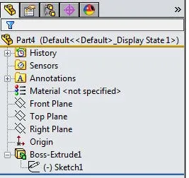
Figure 4: Features and sketches may be placed into part or assembly templates.
The “Sheet Properties” dialog will only be found within a drawing document and can be accessed
by right mouse clicking on a sheet in the FeatureManager Design Tree then going to ‘Properties’.
The resulting dialog is shown in Figure 5.
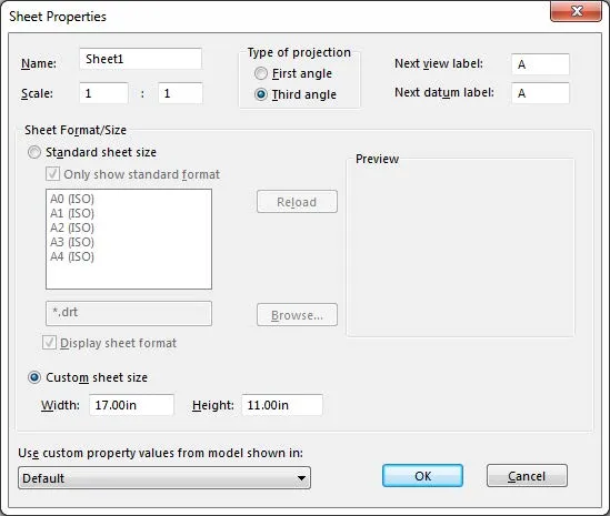
Figure 5: The “Sheet Properties” dialog.
What is the process to update template settings?
No matter what setting is being changed the process of updating the setting within a document
template remains the same. If a setting exists in multiple file types (part, assembly, or drawing) or
multiple templates then that setting will have to be changed on a per type or per template basis
by just repeating the process below:
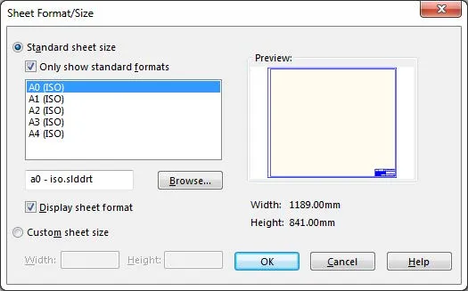
1. Create a new document (part, assembly, or drawing)
If creating a drawing do not select a sheet format but rather dismiss the sheet
format selection dialog (shown below).
2. Go to the location of the setting you wish to change (‘Document Properties’, ‘View’ menu,
‘Sheet Properties’)
3. Change the setting (or place Features or Sketches into the ‘FeatureManager Design Tree’)
then accept the changes
4. Go to ‘File’, ‘Save As’, set the file format to “Part (or Assembly, or Drawing) Template”
5. Overwrite the existing template file to update it or give the file a new name to start
creating multiple templates.
If new template files are being saved into new locations is becomes important to make sure that
SolidWorks is querying that new folder looking for document templates to use. To do this, do the
following:
1. Open SOLIDWORKS
2. Go to ‘Tools’, ‘Options’, ‘System Options’, ‘File Locations’
3. Show folders for ‘Document Templates’ (it should already be this way but make sure)
4. Check the list for the folder location the new templates are saved to and if that folder is not
listed go ahead and add it to the list.
If there are multiple SOLIDWORKS users in the company it may be appropriate to add
the UNC path of a network shared folder to this list for all SOLIDWORKS machines.
One set of updated templates could then be placed into the network shared folder
and all users would be sure to be using the same document templates.
5. Accept the ‘System Options’ dialog
With the file locations double-checked and updated it is now important to refresh what templates
SOLIDWORKS uses by default for imported files (IGES, STEP, Parasolid, DXF, DWG, etc) by doing the
following:
1. Open SOLIDWORKS
2. Go to ‘Tools’, ‘Options’, ‘System Options’, ‘Default Templates’ (shown below)
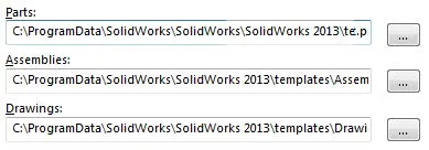
3. Use the “…” buttons to the right of all your templates to re-select which template should
be used as the default template
4. Accept the ‘System Options’ dialog once all templates are refreshed
At this point the document templates have updated settings or new templates have been created,
the default templates used by SOLIDWORKS have been refreshed, and everything is ready for use by
the SOLIDWORKS user(s).

About Ryan Dark
Ryan has been in the GoEngineer technical support team since February 2008 where he most notably provides support for all FEA and CFD software offered by SolidWorks. His most recent accolade is the title of Elite Application Engineer awarded by SolidWorks Corp.
Get our wide array of technical resources delivered right to your inbox.
Unsubscribe at any time.