Negative Pressure Rooms in Hospitals
In hospitals, negative pressure rooms are used to prevent the spread of infectious diseases. To illustrate the concept and effectiveness of these rooms, we’ve run some fluid and particle studies using SOLIDWORKS Flow Simulation.
Positive Pressure Rooms
A positive pressure room is where air pressure is HIGHER than those around it.
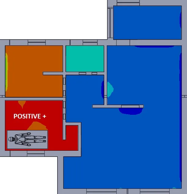
Figure 1 – Positive Pressure Room
One example of how a room could have positive pressure is if it has supply ducts, but no return ducts. The supply air must leave from the POSITIVE room and travel through OTHER rooms in the building to eventually reach a return duct.
Figure 2 – Positive Pressure Flow Animation
Effectively, this means that any particle contaminants produced in the positive pressure room could eventually be spread around to other parts of the building before they can be properly filtered.
Figure 3 – Positive Pressure Particle Simulation
Negative Pressure Rooms
A negative pressure room is where the pressure is LOWER than the surrounding rooms.
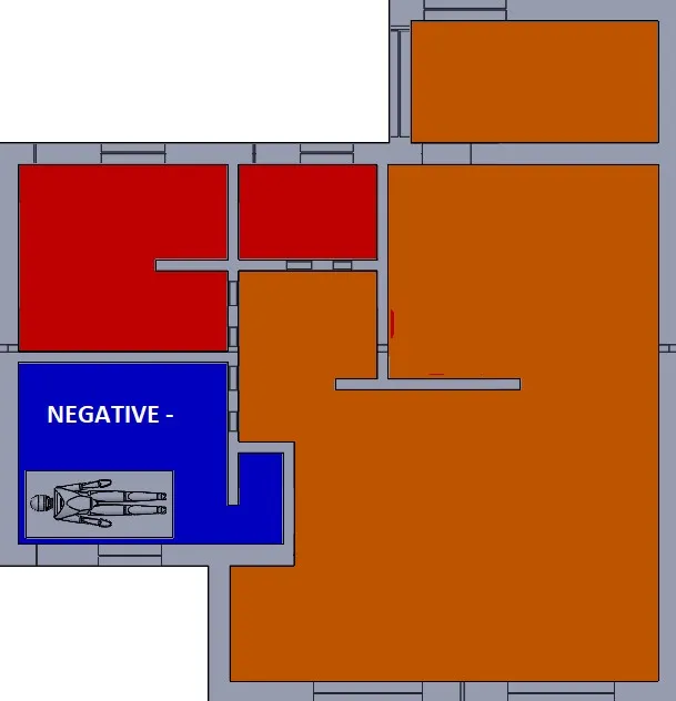
Figure 4 – Negative Pressure Room
A negative pressure room will usually have a return duct with an exhaust fan to assist in forcing air to the filtration system. For a contaminant to travel from the negative pressure room to another room, it would have to “swim upstream.”
Figure 5 – Negative Pressure Animation
Care should be taken to ensure that neighboring rooms or hallways have an adequate supply of air and that the negative pressure room is nearly sealed. These conditions will maintain the pressure differential and entrant velocities needed to keep the contaminants contained.
Figure 6 – Negative Pressure Particle Simulation
Summary
In order to reduce the spread of contaminants or infectious diseases, negative pressure rooms keep air flowing in the direction towards the filtration system.
The fluid-flow and particle simulation tools in SOLIDWORKS Flow Simulation were used to generate the above illustrations and animations. To learn more about the assumptions used in this test, please contact us for more information.
Related Articles
Tank Sloshing Using SOLIDWORKS Flow Simulation

About Shaun Bentley
Shaun Bentley is passionate about applied mathematics and engineering, which led him to pursue and understand real world applications of FEA, CFD, kinematics, dynamics, and 3D & 2D modeling. He teaches many simulation classes to both new and advanced users attending training at GoEngineer. Since 2006, Shaun has been working with simulation tools to solve real world engineering problems. With every new project, he seeks to find ways to push simulation to its uppermost limits, even going so far as to write bespoke code and macros. He has passed the Michigan FE exam and mentors or consults for virtually any industry that uses SOLIDWORKS, especially automotive and automated tools. He is a speed 3D modeling champion and one of the first Certified SOLIDWORKS Experts in Simulation in the world.
Get our wide array of technical resources delivered right to your inbox.
Unsubscribe at any time.