How to Create a SpeedPak in SOLIDWORKS
This guide explains everything you need to know about how to create a SpeedPak in SOLIDWORKS.
Creating a SpeedPak for an Assembly
In an assembly file, you can derive a SpeedPak configuration from an existing configuration.
To create a SpeedPak:
- On the ConfigurationManager
 tab, under Configurations, right-click an existing configuration and select Add SpeedPak.
 - In the PropertyManager:
- Select the faces and bodies that you want to be selectable in the SpeedPak configuration.
- Optionally, select Remove ghost to hide all other faces, which improves performance even more.
- Click the checkmark
A SpeedPak configuration is created as a child of the original configurations. It is identified with ![]() in the ConfigurationManager, and _speedpak is appended to its name.
in the ConfigurationManager, and _speedpak is appended to its name.
No components appear in the FeatureManager design tree. The assembly icon ![]() at the top of the tree indicates that the active configuration is a Speedpak configuration.
at the top of the tree indicates that the active configuration is a Speedpak configuration.
In the graphics area, when you move the pointer over the assembly, only the faces and bodies you selected for the SpeedPak are visible and selectable in the region surrounding the pointer.
To see this behavior, make sure the driver for your graphics card is up to date.
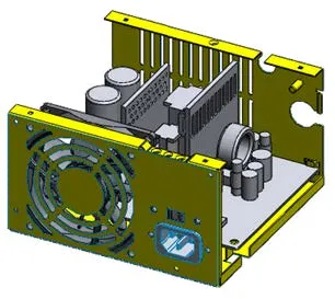
Assembly without pointer
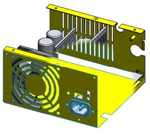
Pointer over assembly
Note that many internal components are no longer visible, as they were not included in the Speedpak configuration.
Creating a SpeedPak from a Parent Assembly
You can create SpeedPak configurations for subassemblies from within a parent assembly. You can choose to include only graphics, or include mated faces, edges, and points as resolved geometry.
To create a SpeedPak:
- In an assembly, select one or more subassemblies.
- Right-click and click SpeedPak Options.
- Click one of the following:
- Create, Mated, SpeedPak: Includes mated faces, edges, and points as resolved geometry, which allows you to create other mates to those entities. Entities included as resolved geometry include entities of the subassembly that mate to other components in the open parent assembly or to the open parent assembly itself.
- Create, Graphics, SpeedPak: Lets you see graphics for the subassembly but does not include any resolved geometry, which yields more performance improvement.
- A SpeedPak configuration is created for the active configuration of the subassembly. If the subassembly is a top-level subassembly, then the SpeedPak configuration becomes the active configuration used by the parent assembly.
Inserting a SpeedPak
You can insert an assembly with a SpeedPak configuration into a higher level assembly.
To insert a SpeedPak:
In the higher level assembly, insert the subassembly by any of the following methods:
Use the Insert Component PropertyManager. Select the SpeedPak configuration under Configurations in the Open dialog box.
Drag from the File Explorer tab in the Task Pane.
Drag from the Design Library in the Task Pane.
Drag from Windows Explorer.
Ctrl + drag within the assembly to insert additional instances of existing components.
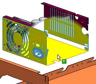
In the region surrounding the pointer, only the faces and body you selected for the SpeedPak are visible. They are the only items you can select for operations such as mating.
To see this behavior, make sure the driver for your graphics card is up to date.
Related Articles
How to Save Annotation Properties in SOLIDWORKS
Missing Cosmetic Threads and How to Fix Them in SOLIDWORKS
![]()
About GoEngineer
GoEngineer delivers software, technology, and expertise that enable companies to unlock design innovation and deliver better products faster. With more than 40 years of experience and tens of thousands of customers in high tech, medical, machine design, energy and other industries, GoEngineer provides best-in-class design solutions from SOLIDWORKS CAD, Stratasys 3D printing, Creaform & Artec 3D scanning, CAMWorks, PLM, and more
Get our wide array of technical resources delivered right to your inbox.
Unsubscribe at any time.