GrabCAD Print Pro Thickness Analyzer for FDM Parts
Stratasys FDM 3D printers provide exceptional design freedom and flexibility regarding materials, build volumes, slice heights, and even soluble support materials when dealing with complex internal channels.
However, it's important to consider the relationship between slice height and fine features. Depending on the nozzle diameter and available slice heights, certain wall thicknesses can be difficult (or impossible) to print reliably. To combat this, we need to understand the limitations of our machines and use that information when designing parts to print.
Thicken Thin Walls
The Thicken Thin Walls tool in GrabCAD Print Pro (located in the Model Settings tab and turned on by default for some printers) ensures that thin-walled features meet the recommended minimum wall thickness for the current slice height.
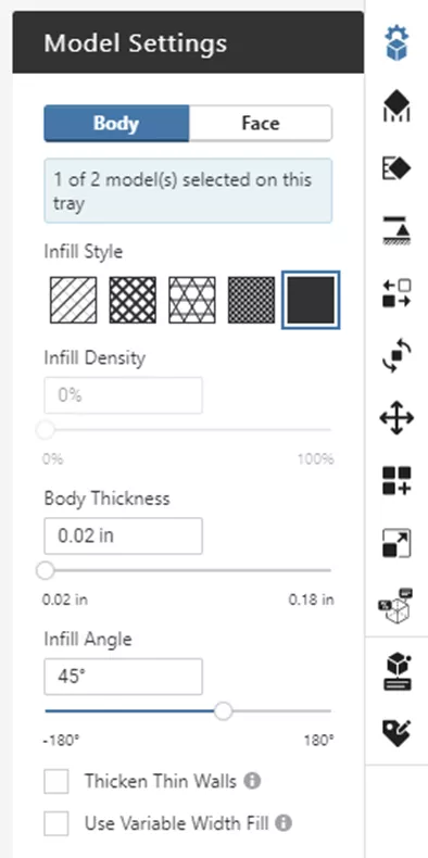
As a rule, each perimeter toolpath ("contour") width is twice the thickness of each layer. As you can see in our model settings, a slice height of 0.010” yields a Body Thickness (wall) of 0.020” by default, because the outer perimeter of the part can't be less than a single toolpath.
Thin-walled features must be at least 2 toolpaths wide (or 4 times the slice height). In this case, a slice height of 0.010” means thin-walled areas should be at least 0.040” thick. That recommended minimum wall thickness is enforced whenever when Thicken Thin Walls option is toggled on. Any features smaller than that value are automatically thickened.
| Slice Height | Toolpath Width (2x) | Recommended Min. Wall |
| 0.005" | 0.010" | 0.020" |
| 0.007" | 0.014" | 0.028" |
| 0.010" | 0.020" | 0.040" |
Figure 1: Approximate rule of thumb, actual figures vary based on printer capability
In this example, printing with a 0.010” slice height, for any feature smaller than 0.040”, Thicken Thin Walls will widen the feature to 0.040”. This is important to note because GrabCAD Print is changing the geometry of the part without user intervention, which might lead to downstream surprises.
In practice, the pictures below show thin walls modeled at 0.010”, 0.014”, and 0.020” on the left-hand side, and 0.020”, 0.028”, and 0.040" on the right. These correspond to the toolpath width for 0.005”, 0.007”, and 0.010” slice heights and their minimum recommended wall thicknesses.
Notice in figure 3 how the walls are automatically thickened to 0.040” (besides the leftmost wall, which is thickened to a single 0.020” toolpath). The as-printed result differs quite a bit from the original design.
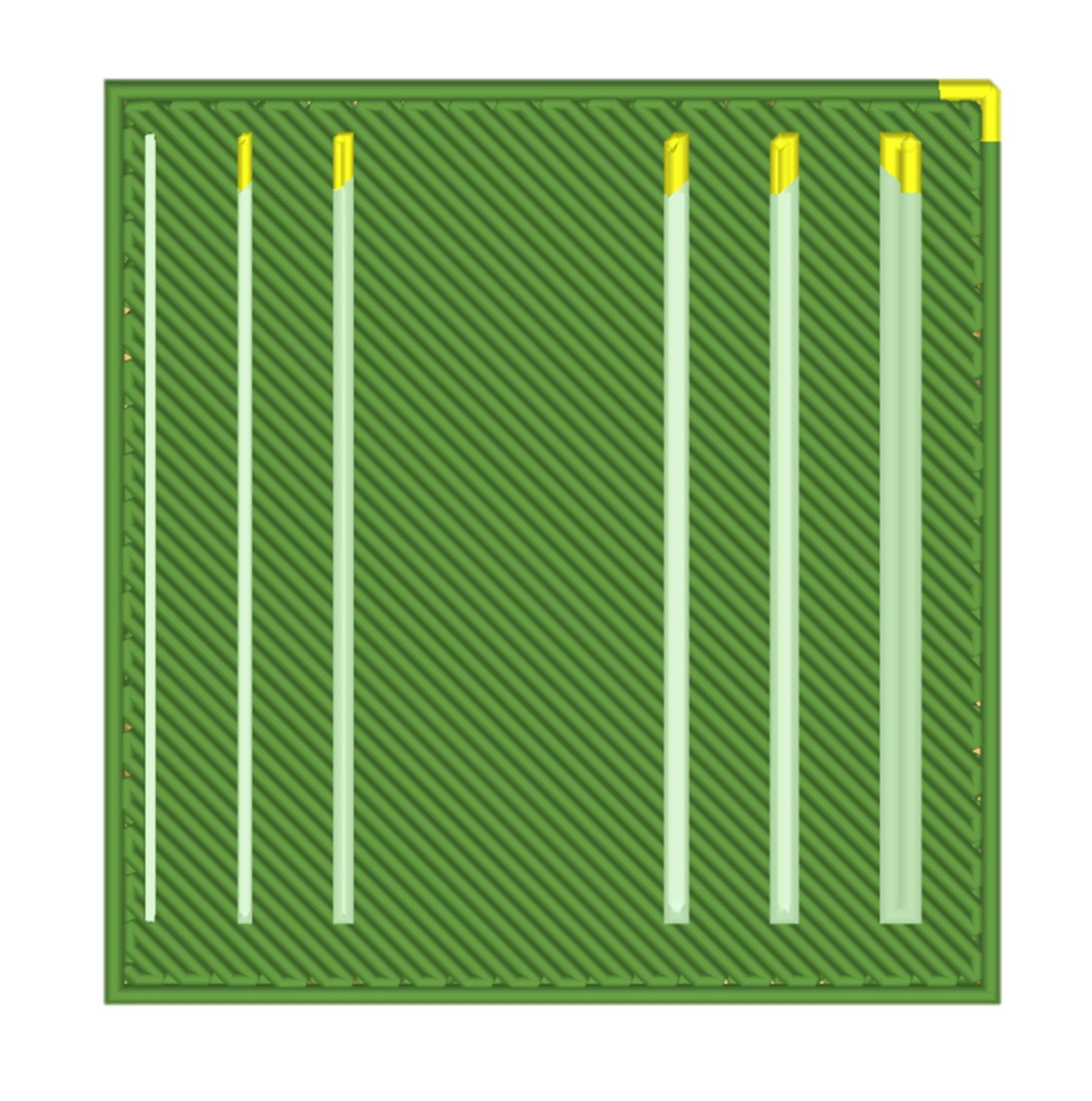
Figure 2: Without Thicken Thin Wall 0.010" slice
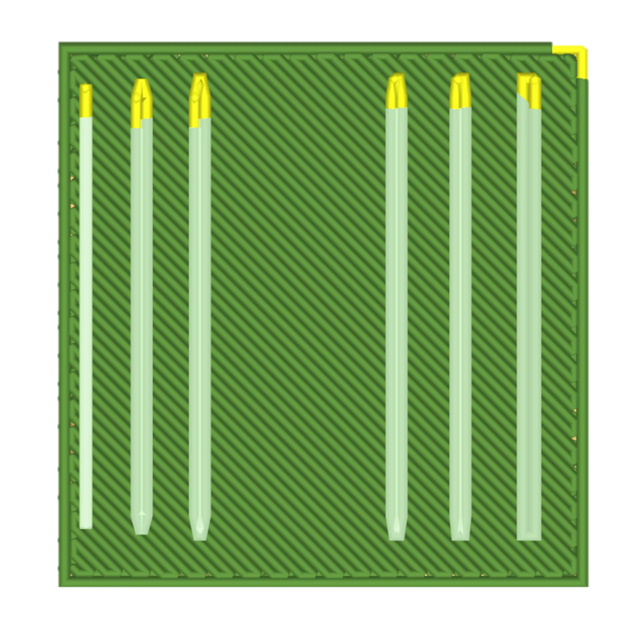
Figure 3: With Thicken Thin Wall 0.010" slice
Thickness Analyzer
Rather than rely solely on the slice preview to identify thin-walled areas, the Thickness Analyzer tool in GrabCAD Print Pro (found in the Model Analysis tab), allows you to quickly evaluate a part and create a pass/fail for thin features. (Figures 4 and 5)
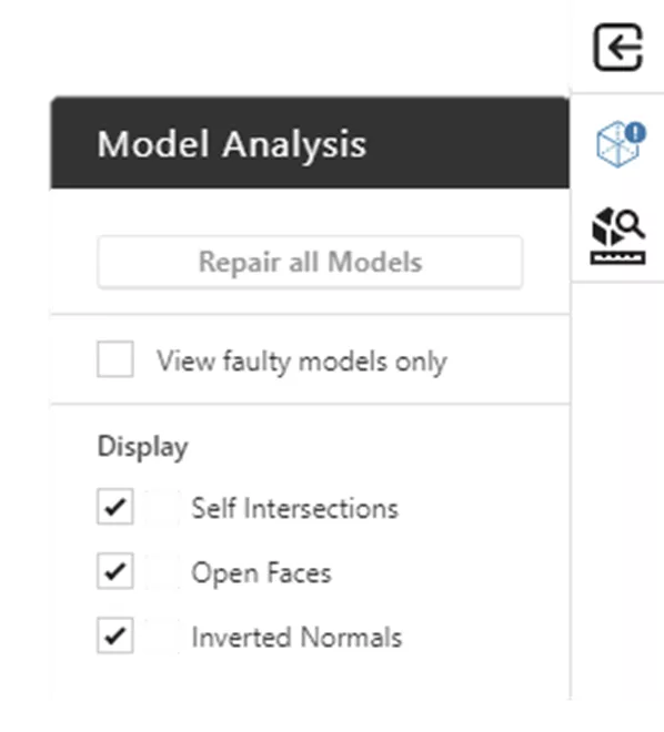
Figure 4: Model Analysis top-right GrabCAD
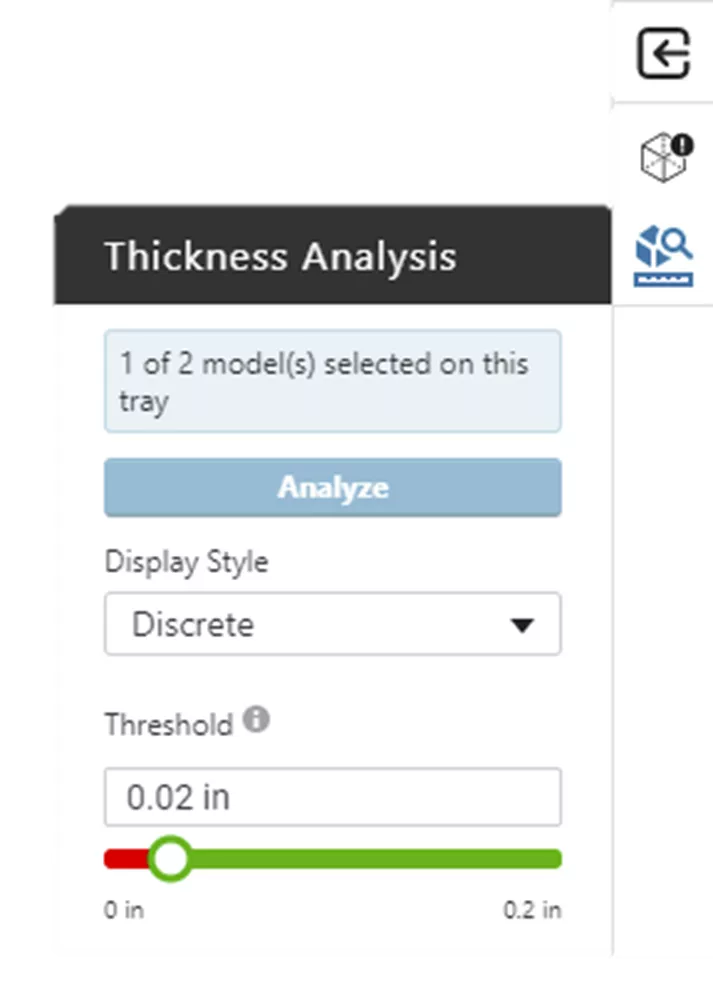
Figure 5: Thickness Analyzer in GrabCAD Print Pro
This tool defines a threshold based on the slice height (in this case the 0.010” slice height defaults to a threshold of 0.020”). Clicking Analyze will highlight any features smaller than this threshold.
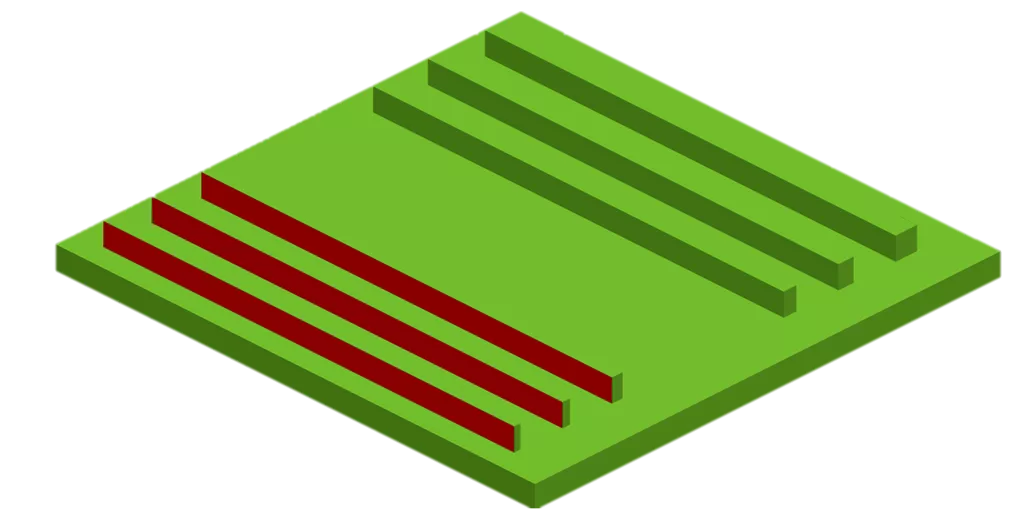
Figure 6: Pass Fail check of thin-walled features
As you can see (Figure 6), all the walls on the left fail, as they are all narrower than the threshold.
From here, we can let Thicken Thin Walls beef these features up to ensure printability of these features, and avoid overlapping toolpaths, or directly adjust these dimensions in CAD to control whether the extra thickness is applied (e.g., to avoid clearance issues between the walls).
Whichever approach you choose, try out these features in GrabCAD Print Pro and see if they are beneficial to you.
Related Articles
GrabCAD Print Pro: Adding Labels to FDM Parts
Create a Custom Purge Tower Using Stratasys Insight Software
GoEngineer 3D Printing Services: Stronger than Ever
Customize Insight Software Interface
About Jonathan Rodriguez
Jonathan is a Digital Manufacturing Application Engineer at GoEngineer.
Get our wide array of technical resources delivered right to your inbox.
Unsubscribe at any time.