Composites in 3DEXPERIENCE CATIA Overview
Composite design functionality in CATIA, reinforced by the 3DEXPERIENCE Platform, puts Dassault Systèmes’ solution at the top of the industry. To see the full power of the solution, it is essential to understand the different processes associated with CATIA Composite Design and how they benefit the user. When designing composites in CATIA, the process is broken down into stages. Furthermore, different methods can be utilized to streamline the design process based on the application. This article provides an overview of the fundamentals and process for designing composite parts in 3DEXPERIENCE CATIA.
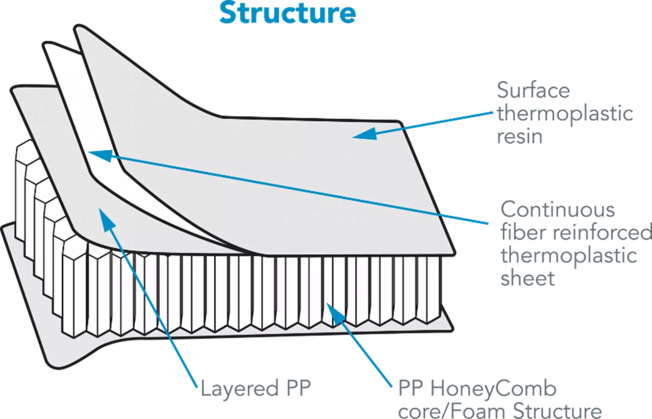
What are Composites?
A composite is a material comprised of two materials that contain differing properties. When these materials are combined, they create a new material with enhanced properties. One of these two materials consists of a set of fibers, known as the reinforcement phase, whereas the other is a continuous material known as the matrix phase. In a composite material, the matrix phase accepts a load over a large area and transfers it to the reinforcement phase, which accepts most of the load. However, the load is only accepted along the direction of the fibers. Therefore, the orientation of the fibers within the reinforcement phase is very important for composites and this is why designing composite parts can be so cumbersome.
Composite materials are seen very often in everyday life. Arguably the most common composite, Carbon Fiber, is the fancy black woven material that sports cars have many of their body parts made of, as well as the frames of the road bikes we see racing in the Tour de France. Fiberglass is another example of a composite material and is often used for boat hulls and hot tub shells.
Engineers will often gravitate toward using composite parts due to their enhanced properties. Composites have a high strength-to-lightweight ratio, are resistant to corrosion and chemical degradation, are nonconductive, and are very durable.
CAD Challenges and How CATIA Combats Them
While composites have many benefits, they do come with their challenges; especially when designing them in CAD. Some challenges that the industry currently faces while designing and manufacturing composite parts are:
Large amounts of data to manage
On average, composite parts contain more design data than the typical solid or surface-based part. A composite part will already start with a surface to define its base geometry and will build on top of that to define the complete composite definition.
Each composite sheet (Ply) is comprised of a contour, material, and fiber orientation. On top of that, we define the sequences, or stacks of Plies, with a common thickness. Also defined, are the interactions between sequences, the drop-off pattern of the Plies, and areas to cut and splice Plies. This is just a portion of the data within a single part, so it is easy to see how the size of the data can easily stack up.
If you know how well CATIA handles large assemblies, you’ll likely recognize that it handles composite parts just as efficiently. For example, the data that is opened initially only loads in enough definition to visualize the data. From there, any relevant data is only loaded once the user activates or probes it. This way, the data loads faster and allows for more fluid manipulation and quicker update processing. For 3DEXPERIENCE specifically, the data pulls from a database upon initial opening, and a compressed copy of the data is stored locally in a cache folder. This cache is updated constantly throughout the session up until the last save. Upon subsequent openings, the data is opened from this cache, as opposed to the database, resulting in quicker load times.
Lack of concurrent engineering
Most CAD software only allows one person to reserve the data at a time. In CATIA, two versions of each part can be reserved, the Reference and the Instance.
- The Reference houses the design tree and subsequently, all the geometry and design history associated with the part.
- The Instance is a copy of the Reference and is instantiated within assemblies. Therefore, one user can be updating the geometry of a part while simultaneously, another user is instantiating and positioning the part within required assemblies.
No integration between analysis and design
For most CAD software, there is no link between the CAD, simulation, and manufacturing data. More than likely, the CAD must be exported to a format compatible with the simulation and manufacturing software. As a matter of fact, most composite definition for CAD is built within the simulation software. This complicates the design process because the composite definition cannot be linked back to the CAD and instead, must be manually recorded and delivered to the design and manufacturing teams. This also extends to the manufacturing results and developments.
Within 3DEXPERIENCE CATIA, CAD, manufacturing, and simulation data are linked within one platform and database. This eliminates the need to export and convert the data and allows for every result, document, and detail to be linked to the data as well. This allows for easier collaboration and ensures that each team is referencing the correct and most recent version of each other’s data.
Lack of ability to predict manufacturing issues upfront
Currently, the most common practice for determining manufacturing issues when it comes to composites is to deliver the design to manufacturing, have them test the process via physical prototype, and report back any issues that occur for the design team to mitigate and fix.
3DEXPERIENCE offers a feature called Producibility for Hand Layup, which simulates the Hand Layup process and checks for issues that may occur, such as fiber deformation and insufficient roll width.
CATIA Composites Design Approaches
Within CATIA Composites Design is the preliminary process of defining Plies and the order in which they stack up. This process can be accomplished using one of three approaches: Grid, Import, and Manual Approach. The Grid Approach is currently the standard approach in the industry. Therefore, this article will focus on Grid Approach and will tie in how the Import and Manual Approaches fit into this process while discussing the use cases and benefits of each.
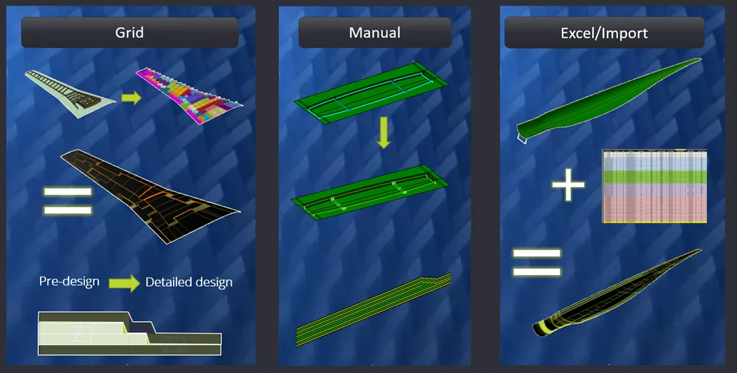
Grid Approach Introduction to Composite Design
In the Grid Approach, the user will develop intersecting wireframes on the base surface to define a grid. The intersections of this grid define cells. The cells are assigned material and fiber direction properties and are then arranged to define the contour of the Plies as well as the stack-up order of the Plies.
The Grid Approach is preferred when designing large and complex composite parts such as wings, fuselages, and wind blades. It is also preferred when it is necessary to consider structural elements such as stiffeners, stringers, and frames.
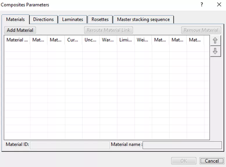
Composite Definition and Ply Generation
Before the composite part can start being built, the Composite Parameters must first be defined. The Composite Parameters are a set of variables that are utilized and accessed throughout the design and help expedite the process by defining them upfront and keeping them in a single place. The primary variables defined here are the materials, associated fiber directions, laminates, and Rosette. The Rosette is the axis system that defines the directions of the fibers relevant to the surface that the Plies are being laid on to.
Determine Base Surface
The Base Surface, also known as the Support, Reference, or Tooling Surface, is the surface on which the composite material is laid and it acts as the basic geometry of the part.
This surface can be designed directly within CATIA or can be imported from a 3rd party CAD in a neutral format such as STEP or IGES. Users will benefit by designing the Base Surface within CATIA, especially if there are updates to the geometry of the base surface.
The connective nature of the surface to the composite definition will allow for easier updates to the composite definition as well as the manufacturing and simulation data with less rework and error mitigation.
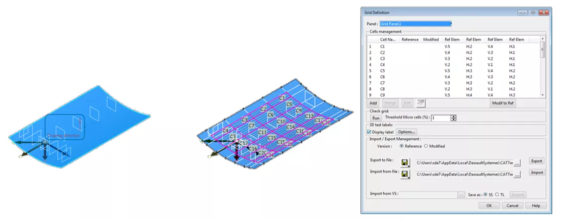
Defining Grid Panel and Creating the Grid
Once the Base Surface is determined, the user is ready to develop the grid on the base surface. While doing so, the user is also assigning a Rosette (if more than one was created in the Composite Parameters. If only one was made it is applied by default) as well as assigning a Draping Direction. The Draping Direction determines which side of the Base Surface the composite Plies are placed and stacked.
Next, the Grid is developed. In this process, the user will assign wireframes to the surface. These wireframes intersect perpendicular to one another to form a Grid. As a best practice, it is ideal to build the wireframes using planes that intersect with the Base Surface and are tied to the structural elements which define the desired application of the composite Plies. By doing so, updates to the structural elements will more readily be pushed to the composite definition.
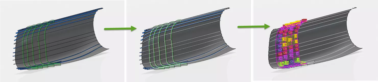
The intersections of the Grid will implicitly create cells. The user will then assign a material and fiber direction to each cell, layer by layer, until a pattern of stacked materials/fiber directions are defined for each cell. The stack pattern of materials/fiber directions for each cell is what’s known as a Laminate. The Laminates can be defined within the Composite Parameters as well as at this step.
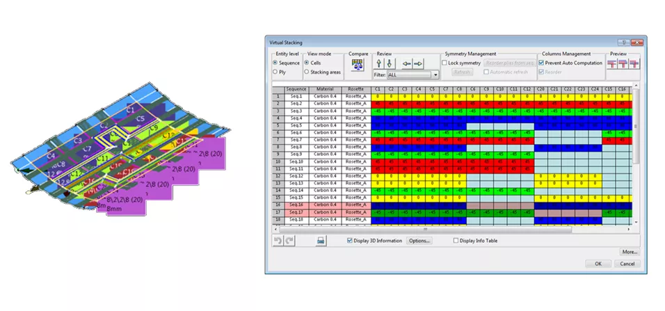
Create and Manage Virtual Stacking
Once the Ply materials, fiber directions, and laminates are defined, the user will move on to use the Virtual Stacking tool.
Virtual Stacking is the preliminary step to generating the Plies in 3D and in the tree. This step consists of combining the cells to define the contour of each Ply at every layer in the stack to fully define the Sequences in the design.
A Sequence is a stacking of Plies resulting in a common thickness. For example, two “stacks” of Plies that are the same thickness belong to the same Sequence. The Virtual Stacking Tool also affords the user the ability to add, remove, or modify Plies and Sequences. Therefore, this acts as a good tool to update and regenerate the Plies in 3D.
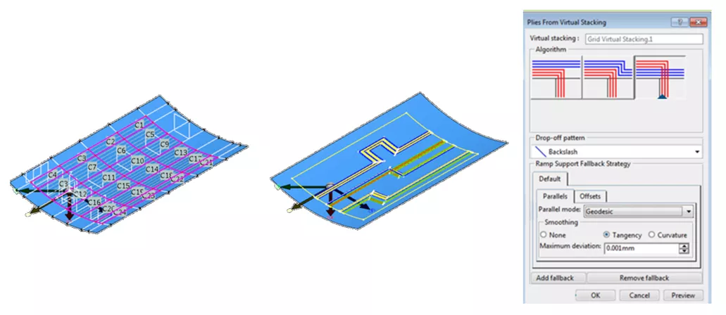
Create Plies from Stacking
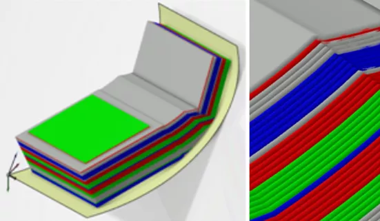
Using the Create Plies from Virtual Stacking tool, Plies are generated in the design tree and in 3D as color-coded wireframe and surface representations. This tool provides three different algorithms to generate the Plies.
- Minimal Crossing – Overlapping of Plies will be limited but may result in more material and a heavier final weight.
- Weight Saving – Less material will be utilized but may result in decreased performance.
- Minimal Crossing and Weight Saving – If there is no design intent to go one direction or another, choosing this option is an ideal middle ground.
Before generating the Plies in 3D, the user has the option to generate a Tree Mask for the Plies generated using the Grid Design approach. This will create a small icon that hovers over each node in the tree that represents a Ply using the Grid Approach. This feature is beneficial when multiple approaches are used to develop Plies within the same part.
Excel/Import Approach
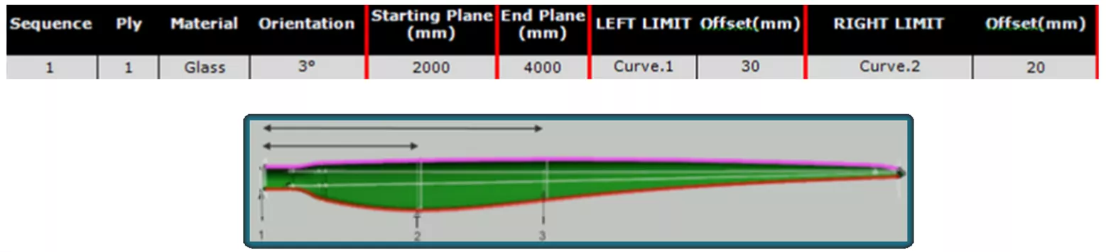
The Excel/Import Approach uses the same process as the Grid Approach, but the definition of the plies and sequences are defined within an external table. Upon importing the table into 3DEXPERIENCE the definition is generated in 3D and in the tree.
In this approach, the user only needs to set up the base surface and define limits and offsets of the wireframes to be used for the grid. The remainder of the Ply definition is generated from the information contained in the table.
Since CATIA enables the user to export the composite definition to a table, this approach is ideal when the part being designed is meant to emulate a legacy or production part with a proven composite configuration.
Manual Approach
The Manual Approach is essentially the “brute force” method of developing the Plies in 3D. In this approach, the wireframes on the Base Surface are used, not to define a grid, but instead to define the contour of the Plies. In this approach, each Ply is defined one-by-one by defining the contour, material, and fiber direction for each Ply before moving on to the next one. This is repeated until every Ply in the part is defined.
This approach is ideal when building simple composite parts with a limited number of Plies such that it is faster to develop the Plies one-by-one instead of building a grid and running through the Grid Design Approach. This approach is also ideal to use when building conceptual phase parts. The workflow associated with building the contour and definition of the Plies affords users more freedom to test out different concepts and “tweak” the definition of the Plies.
Finally, the Manual Approach is the perfect method to use when the design incorporates Cores. A Core is a piece of non-composite material that is layed into the Ply stacking to achieve a specific material property. In the case of Cores, the Sequences used to define the Ply stacking are laid onto two different domains, below and above the Core. In CATIA, Sequences of different domains are of different Groups in the design tree. Simply put, the Manual Approach makes it easier to build the extra Groups needed to facilitate the extra domain that is created when incorporating a Core.
Finalize the Design
Edge of Part (EOP)
The Edge of Part (EOP) defines the boundary of the composite part. In CATIA, there are two different types of EOP, the Engineering Edge of Part (EEOP) and the Manufacturing Edge of Part (MEOP).
The EEOP is the ideal, precise boundary of the part as designed by the engineer. The MEOP corresponds to the actual boundary of the part as it is manufactured while considering variables such as tolerance and tool type.
Within 3DEXPERIENCE CATIA, the Material Excess function will extend the EEOP to the MEOP so that certain manufacturing constraints can be taken into consideration during the design phase.
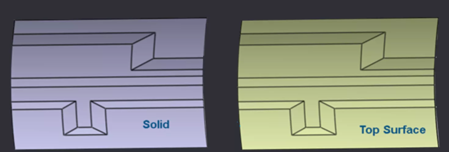
Create Solid and Top Surface
The Composites Design app in 3DEXPERIENCE CATIA gives users the ability to develop Solids and Top Surfaces from Iso-Thickness Areas.
Typically, the Solid is used for visualization purposes such as checking for irregularities or voids as well as providing a real enough representation to be used for renderings and presentations. The Solid can also be used for light FEA analysis efforts.
The Top Surface is used to provide a reference for defining the orientation and stacking sequence of composite Plies.
Probe and Analyze Composite Data
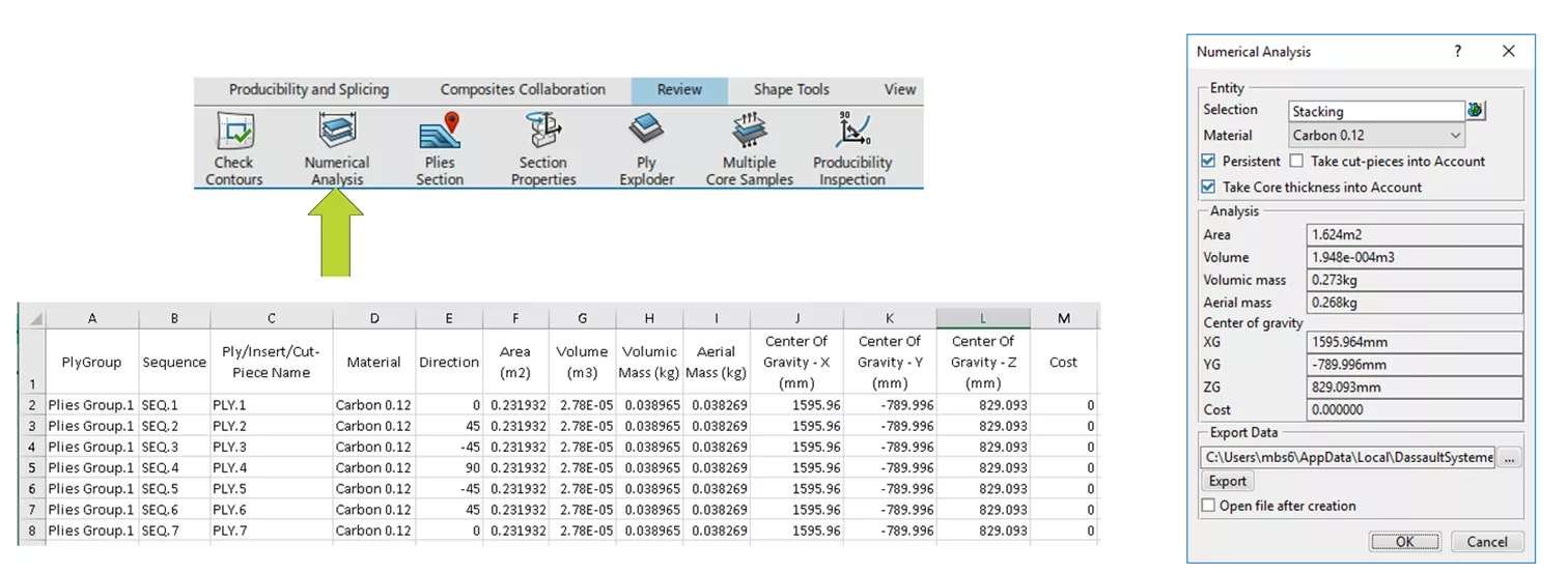
Numerical Analysis
The Numerical Analysis tool gives users the ability to capture the physical properties of various factors within the composite definition such as Area, Mass, Volume, and Center of Gravity. This information can then be exported in a table-based format.
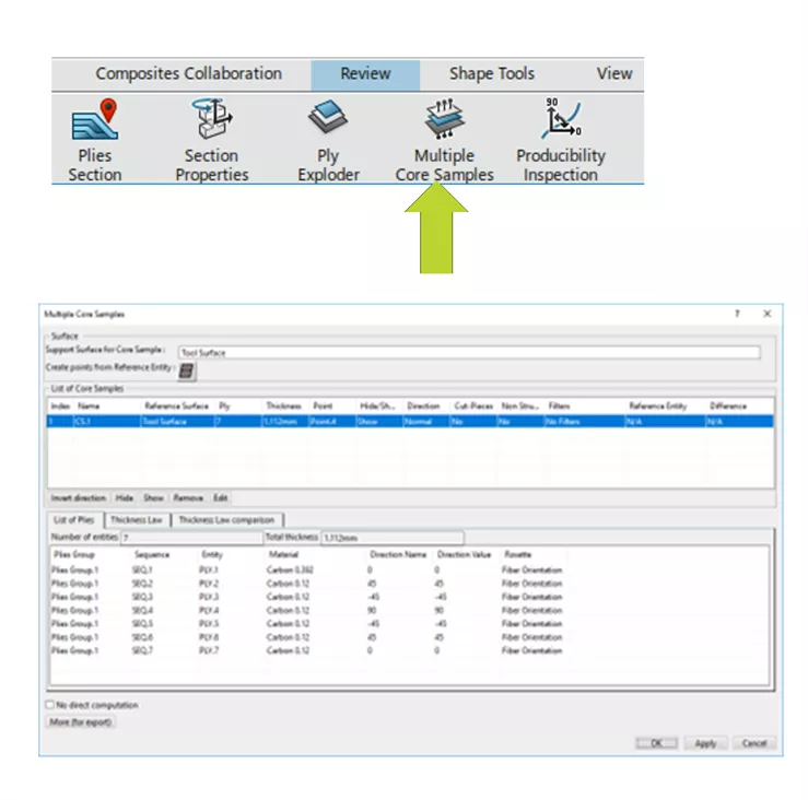
Core Sample
The Core Sample tool grabs composite information on the part at a specific point or from several points at once. The points in CATIA have specific coordinates so users can reliably understand where the data is being drawn from. At these locations, users can gather information such as the name of the Ply, the associated material, fiber direction, Rosette, the Sequence, and the Group the Ply belongs to. Additionally, the thickness and number of Plies at each point can be gathered.
Section Cut
Users can visualize a section at a specific plane using the Section Cut tool. The section can be scaled for better visualization.
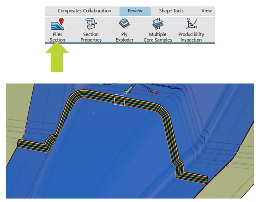
A range of output options can be selected to modify how the scaled section is viewed.
- Section Type
- Realistic
- Schematic – This option does not create realistic raps, making the computation time shorter.
- Display Type
- Surface – Each Ply section is a planar surface.
- Block Linear – Each ply section is a closed contour.
- Light Linear – Each ply section is a curve.
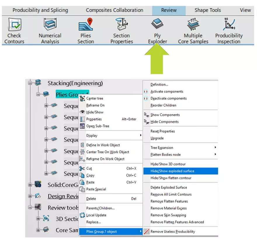
Ply Exploder
Like the Section Cut tool, the Ply Exploder provides the ability to scale the Ply definition but is applied to the entirety of every ply instead of a section cut. Users can choose to define an offset distance between each Ply to distinguish one Ply more easily from another.
Just like the Section Cut tool, the Ply Exploder tool offers a range of visualization options.
- Tessellated Constant Offset – Generates a tessellated surface corresponding to a constant offset of the Ply shell.
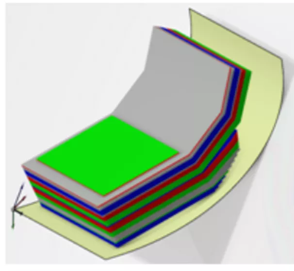
- Draped Tessellated Surface – Acts as a surface representation of the Plies that were draped over a complex shape.
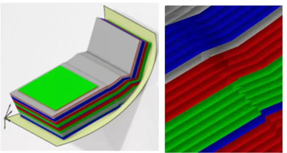
- Draped Tessellated Skin - Generates a closed skin that represents all the exploded plies. For all plies, a draped tessellated surface is generated as described above, then an offset equal to the scale x ply thickness is applied and triangles are added to create a closed skin.
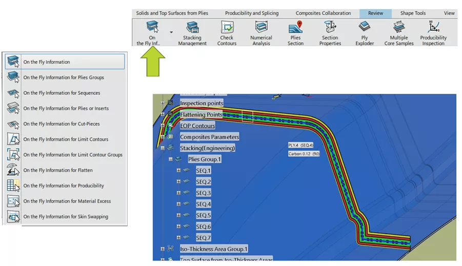
On The Fly Information
The On the Fly Information tool effectively turns the user’s cursor into a probing tool to display composite information of various portions of the data. The user can gather composite-specific information such as Ply Name, Material, Fiber Direction, Sequence, Plies Group, and Draping Direction. The user can filter which data they are probing. The available display filters are:
- Plies Groups
- Sequences
- Plies or Inserts
- Cut-Pieces
- Limit Contours
- Limit Contour Groups
- Flatter
- Producibility
- Material Excess
- Skin Swapping
Manufacturing Preparation
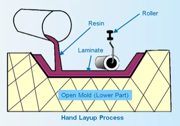
Producibility for Hand Layup (Dry Layup)
The Hand Layup process (also known as “Dry Layup) is the manufacturing procedure of first laying out the Plies as dry fabric (reinforcement phase) and then applying the resin (matrix phase) as a secondary step.
The Producibility for Hand Layup tool simulates this process and checks for fiber deformation as well as sufficient roll-width of the dry fabric when compared to the Flat Pattern of each Ply. CATIA affords the ability to optimize this process by adjusting the following factors.
- Seed Point – The first point of contact where the fiber propagation starts.
- Seed Curve – Serves as a reference for the shape, size, and orientation of the composite layers that need to be applied. It defines warp and weft (longitudinal and transverse) directions of fiber deformation to be measured.
- Mesh Resolution – Deformation of the fibers is measured at every intersection of the mesh. The user can adjust the distance between each intersection and thus control the resolution of the analysis.
- Thickness Update – Toggling this option will run the Producibility while considering the increasing thickness as more Plies are stacked. This is especially useful when Plies are laid over a radius since that radius will increase along with the thickness. This option can be toggled off to reduce the analysis computation time.
Working with Producibility Results
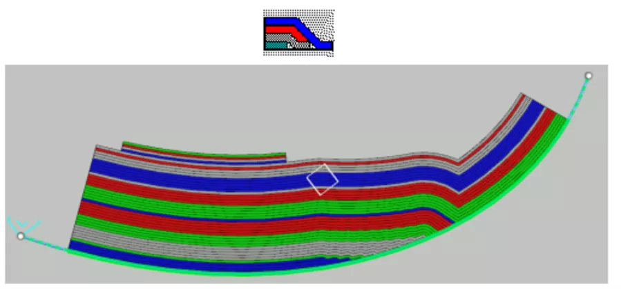
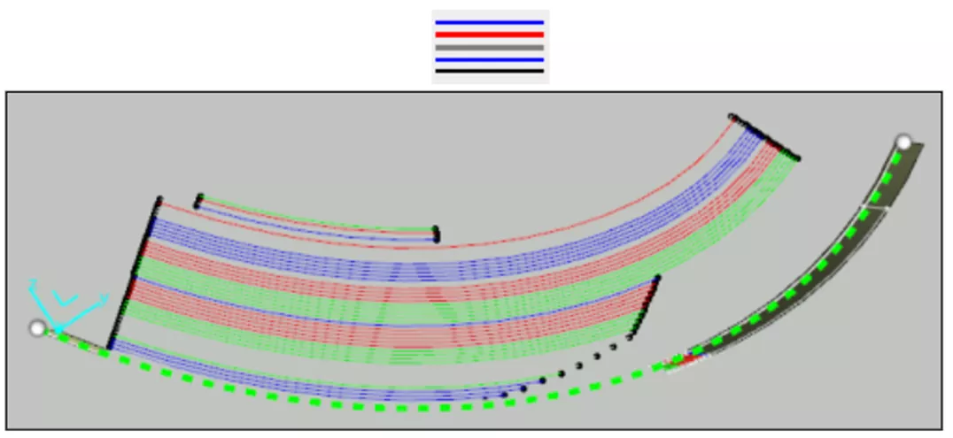
While checking the deformation of the Plies during Hand Layup, the range of acceptable deformation is defined by the user. The user can define a limit angle which denotes when the deformation has reached an unacceptable value as well as a warn angle which denotes that the deformation is within specification but approaching the limit angle. As the Producibility for Hand Layup is run, CATIA generates a mesh on the part representing each Ply as is it placed on the tool starting with the Seed Point. The resulting mesh will be represented with three colors which denote the deformation state:
- Blue Mesh – The deformation of the Plies is within specification.
- Yellow Mesh – The deformation is in between the warn and limit angle.
- Red Mesh– The deformation has exceeded the limit angle.
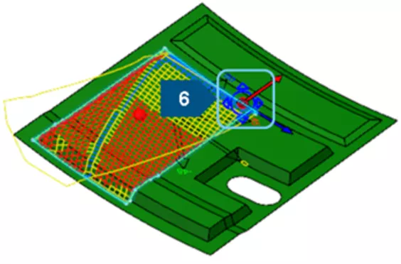
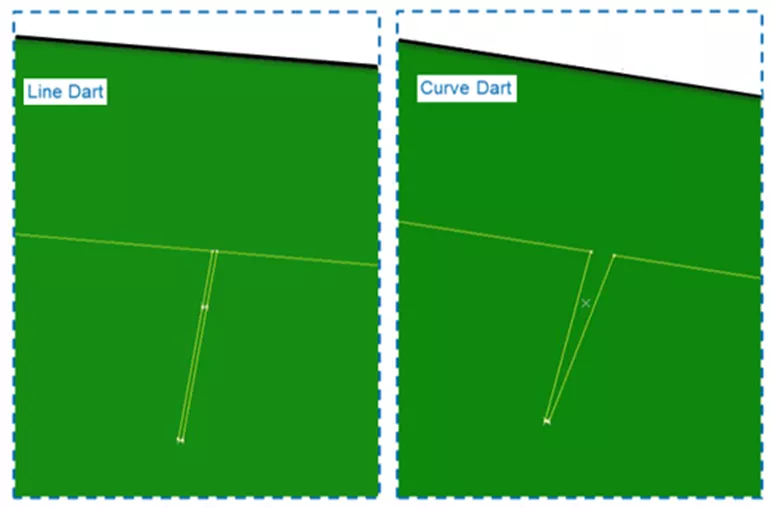
To compensate for deformations that exceed the limit angle, the user can implement a Dart or relief cut on the fiber sheet. CATIA affords two options to implement a Dart:
- Line Dart - The Dart is defined between two points.
- Curve Dart – The Dart is defined by a wireframe curve.
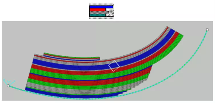
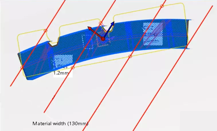
The Producibility for Hand Layup also checks the roll width of the fiber sheets against the Flat Pattern of the Ply. In the image below, the yellow contour represents the flat pattern of the Ply while the red lines represent the width of the fiber roll.
The scenario below shows that to cover the entire flat pattern of the Ply, the fiber material must be rolled out, cut, rolled again, and spliced until the flat pattern is entirely accounted for. The fiber sheets that are cut and spliced from the roll are known as Cut Pieces. The Producibility for Hand Layup tool will generate the splices for the Cut Pieces and afford the user a few options for generating the splices:
- Multi-Splice – Allows for overlap of the fiber sheets when splicing together.
- Butt Splice – Restricts overlap of the fiber sheets when splicing together.
- No Splice Zone – Restricts splicing of any kind for the areas specified.
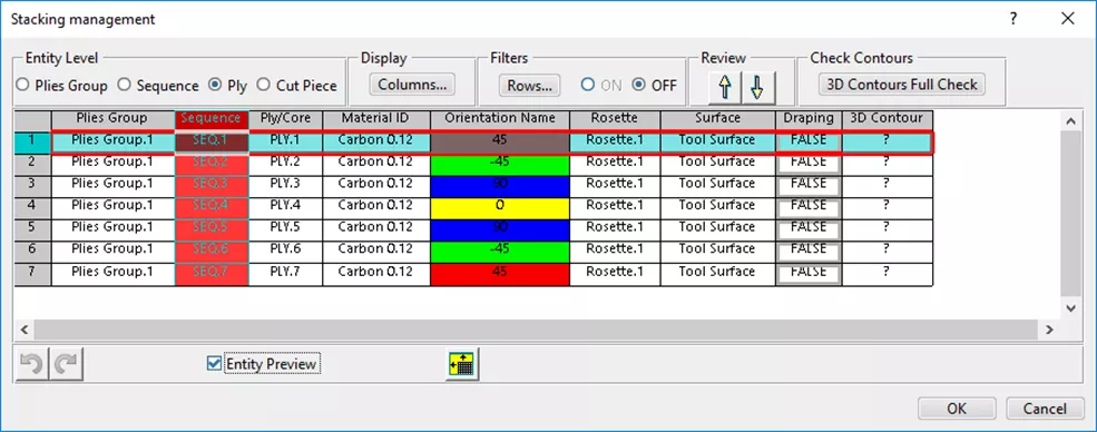
Stacking Management, Flat Patterns, & Export/Import
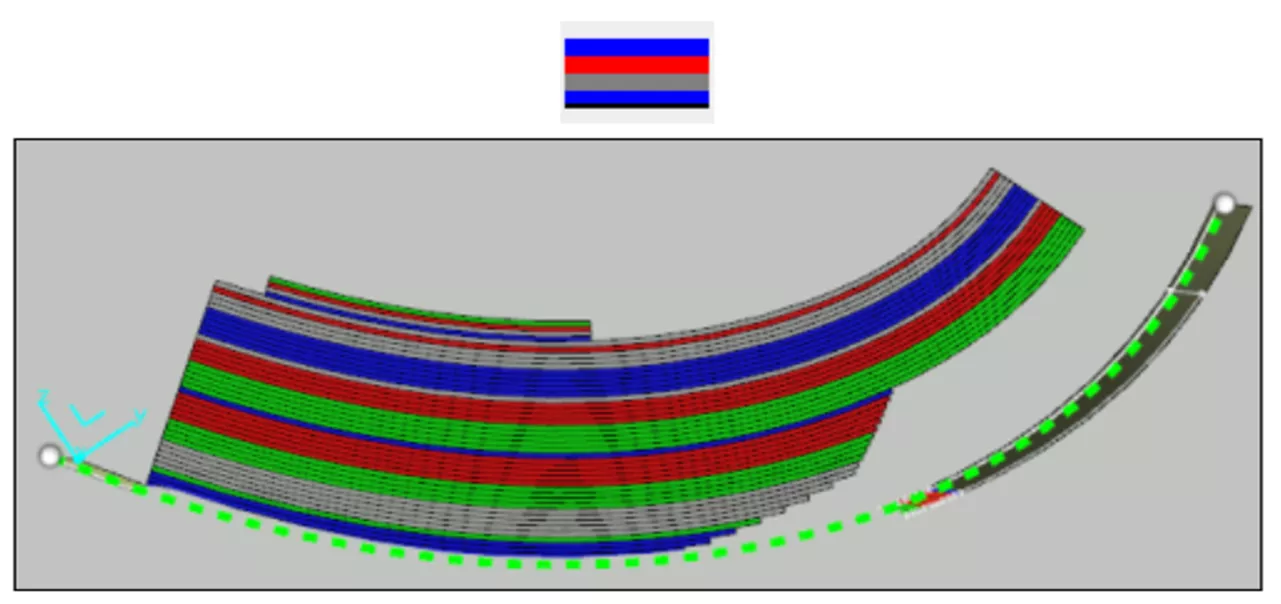
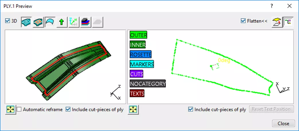
CATIA Composites Design app in 3DEXPERIENCE provides a range of review tools. The Stacking Management tool offers the ability to preview each Ply in its manufactured state as well as its Flat Pattern.
The Flattening command creates a flattened representation of the Ply to be used in the manufacturing definition known as the Flat Pattern. Both the Flat Pattern as well as the entire composite definition of the part can be exported to various formats including IGES, DXF, or XML, depending on the data type.
As a note, 3DEXPERIENCE CATIA can import CATIA V5 composite parts with full history. Typically, 3rd party data will be imported into most CAD software as dead geometry, meaning the geometry is brought in as a single solid body without any command history within the design tree. However, when parts are brought in from certain release years of CATIA V5 they are imported with the full design tree history enabling the user to modify the legacy composite definition directly within 3DEXPERIENCE.
Composites Drawing and Ply Books
Once the composite definition is complete, the 2D drawings can be developed in the forms of Composite Drawings and/or Ply Books.
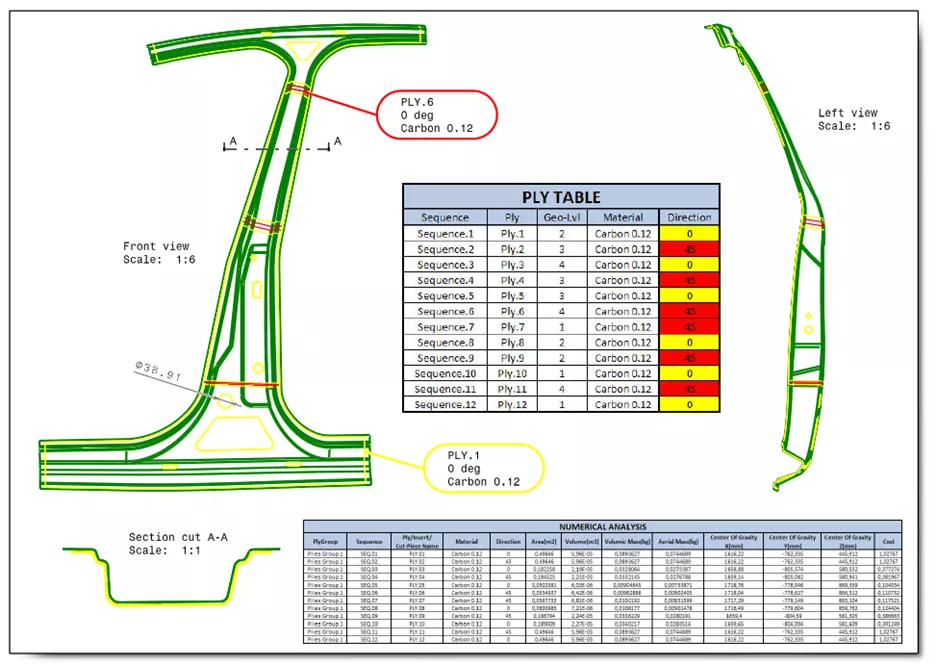
Composite Drawings are essentially an engineering drawing. This drawing displays the final part with all Plies represented in their manufactured state.
The Composite drawing also includes the Ply Table and Numerical Analysis which display the composite and physical information, respectfully, associated with the part.
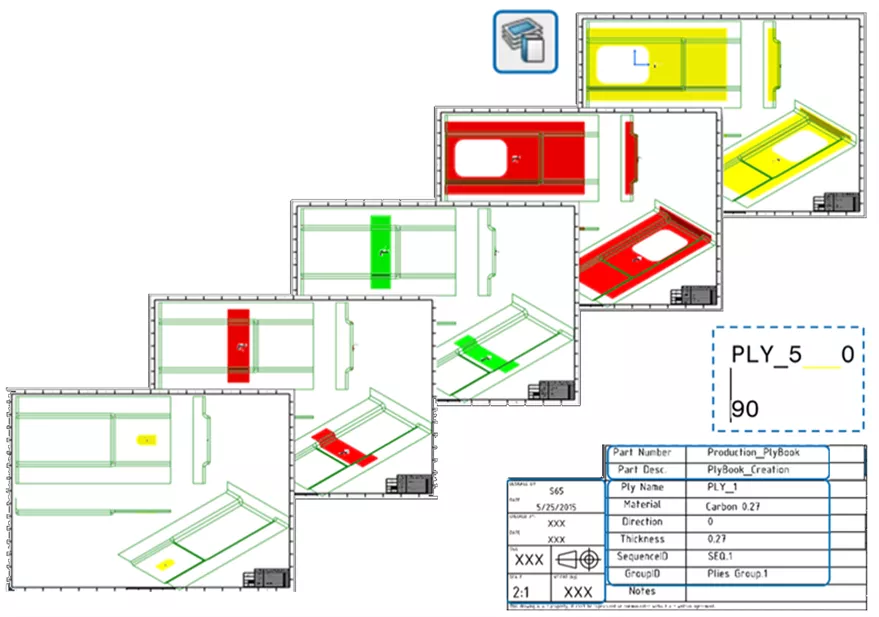
The Ply Book will take each Ply or Sequence and assign each to their own drawing sheet. Each drawing sheet shows the individual Ply/Sequence in manufacturing position with various supporting views. The Ply Book is ideal for developing manufacturing instructions and standard operating procedures.
Export Laser Projection
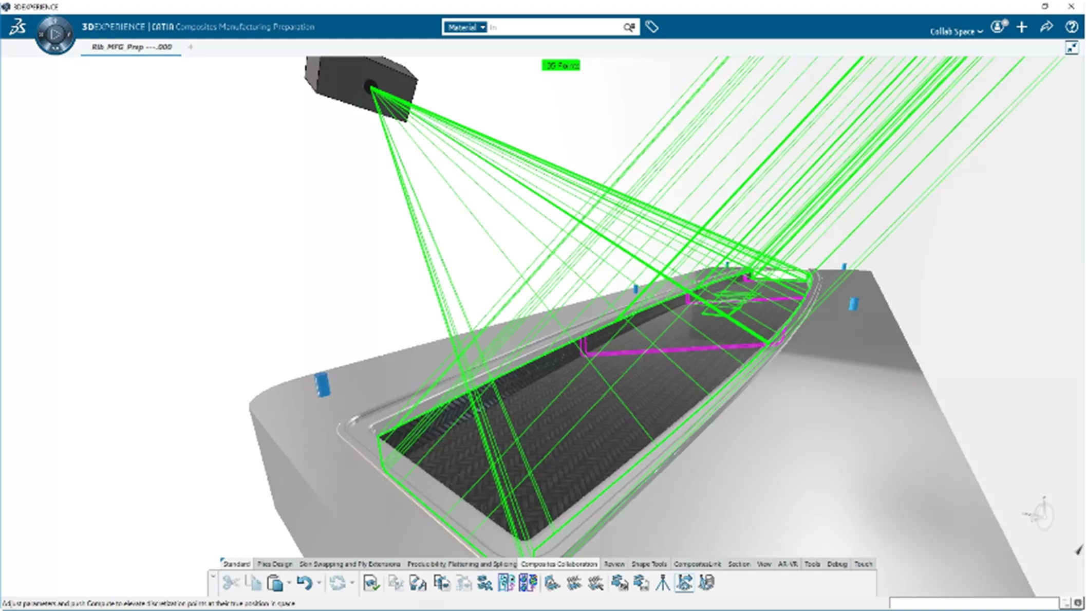
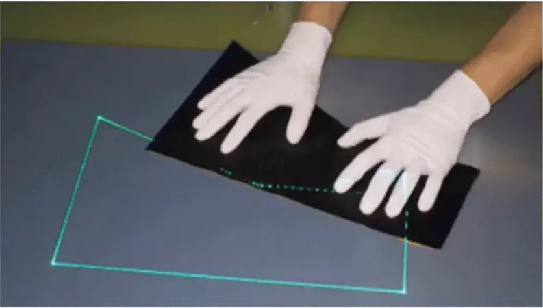
Finally, CATIA provides the ability to export composite definition to support VIRTEK laser projection systems in .ply or .cal formats. The laser projection hardware assists in the hand layup process as it projects an accurate and precise outline of each Ply onto the tooling surface in manufacturing position, thus enhancing, and expediting the hand layup process.
Bonus: CAD-Associated Composites Simulation
Simulation can be hugely beneficial for understanding the manufacturing and performance behavior of composite designs. However, these materials are difficult to capture and correctly assess in FEA. To address this, composite design data created in 3DEXPERIENCE CATIA can be directly linked to 3DEXPERIENCE STRUCTURAL and its composite analysis tools, saving time and increasing accuracy in simulation modeling, which goes on to save on physical prototyping and increase product quality. You can learn more about simulation with composites in my colleague's blog post on the topic, Intro to CAD-Connected Composites FEA.
Conclusion
If you would like to know more about CATIA Composites Design in 3DEXPERIENCE and CATIA V5 as well as our range of offerings at GoEngineer, our 3DEXPERIENCE CATIA product page and our CATIA Buying Guide are great places to start. To learn more, check out our recorded webinar that explains composites in 3DEXPERIENCE CATIA in further detail.
![]() Composites in 3DEXPERIENCE CATIA - Webinar
Composites in 3DEXPERIENCE CATIA - Webinar
You’re Doing Great with SoLIDWORKS. What Next?
Learn how to raise the bar and stay competitive with generative design, design optimization, totally new CAD modelers, and additional CATIA capabilities here.
3DEXPERIENCE CATIA WHITEPAPER
10 Reasons 3DEXPERIENCE CATIA Gives Mechanical Engineers An Advantage
Having the right tools for the right job can massively increase engineers' productivity, and there's no time to lose in today's competitive environment.
3DEXPERIENCE CATIA companies can experience:
- A 20% to 50% gain in productivity thanks to superior modeling and assembly management capabilities
- Seamless workflows and faster processing with cloud-based data management and high-performance cloud computing
- Up to a further 30% improvement in productivity thanks to a unified modeling and simulation environment and design for manufacturability
Download this whitepaper for a closer look at what makes CATIA the ultimate mechanical design tool.


About Tim Ramos
Tim Ramos is a Senior Specialist with GoEngineer based out of Denver, Colorado. He graduated from Rensselaer Polytechnic Institute in 2014 with a degree in Mechanical Engineering and Material Science. After graduation, Tim worked with Honda R&D designing the body/frame structures of their vehicles. He designed sheet metal parts using advanced surface design and plastic injection molded parts using solid part design in CATIA V5. In 2018, Tim transferred over to his CATIA Specialist career path and has been focusing on all things related to CATIA V5-6 and 3DEXPERIENCE CATIA ever since.
Get our wide array of technical resources delivered right to your inbox.
Unsubscribe at any time.