Occasionally design engineers need to be specific in how a part is bent for the part to function correctly. To do that, we need to create something commonly called a “Process Plan Drawing”. What this document will show are the steps needed to create the part as it is meant to be used. The problem is, how can we do that in the most efficient way.
Process Plan Drawing
The use of Configurations is very important in this process. If you need more information on Configurations and how to use them, see your SOLIDWORKS Essentials Class Book: Lesson 10. We have many configuration related articles in our knowledge base at goengineer.com/search if you would like to look there as well.
Ok let’s get started.
First, let’s look at our part:
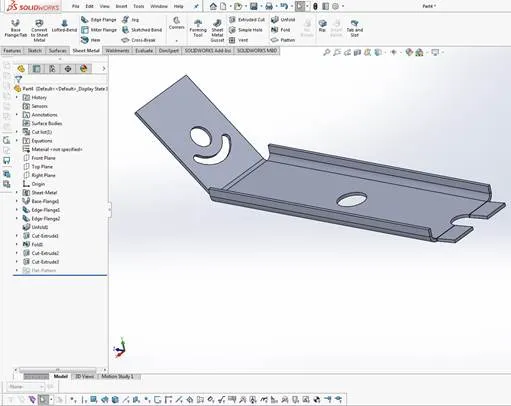
It’s a simple part that has 3 bend features that we need to specify the order of bending to manufacturing.
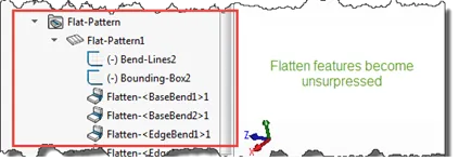
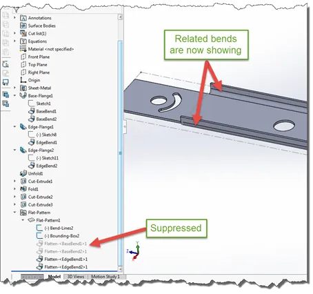
First thing to do is to look at the Flat Pattern feature:
As you can see, with Sheet Metal functionality, each of the bend features has a related Flatten feature. You can use these opposite features to control how they display to show the build order.
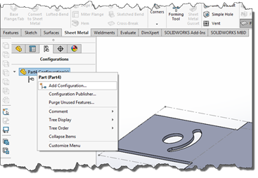
Keeping those in mind, let’s now make some Configurations of the existing part.
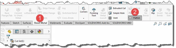
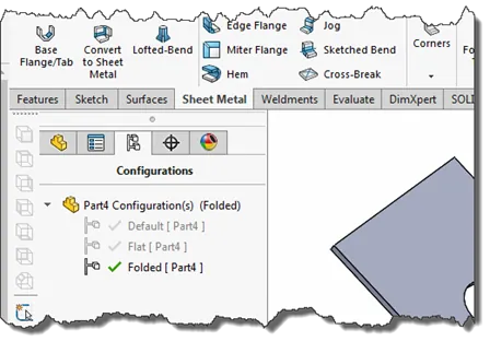
The first step in this process is to create one configuration for the Flattened part and one of the final, Folded part. Let’s call these “Flat” and “Folded” respectively. Start with the Flattened. Go to the “Sheet Metal” tab and select the “Flatten” option:
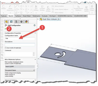
With the Flatten features unsuppressed, create the “Flat” configuration:
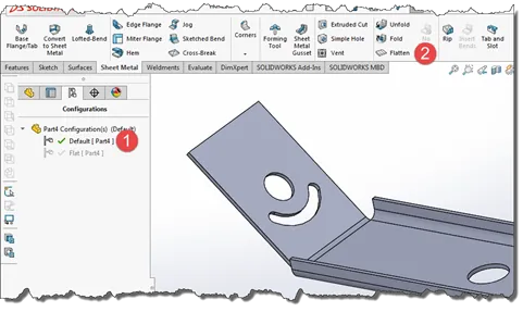
Change back to the “Default” Configuration and unselect the “Flatten” feature:
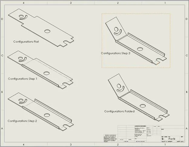
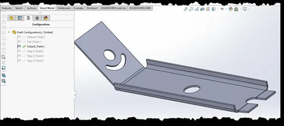
Create the Configuration “Folded” in the same process we created the “Flat” configuration. You should now see configurations named “Flat” and “Folded” (the Default configuration is created automatically. Ignore it for this example).
The trick here is to make the “Flat” configuration as the active configuration by double clicking it. Configurations that are created will duplicate the settings of the active configuration when they are created. Make 3 new configurations, same process as before, called “Step 1”, “Step 2” and “Step 3”.
These will all have the same settings as the “Flat” configuration.
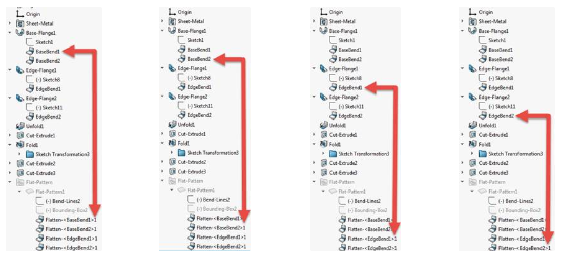
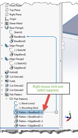
Once these are created, make “Step 1” as the active configuration, go to the Feature Manager Design Tree and expand the “Base-Flange1” feature, and each of the features that have a bend in them. Also expand the “Flat-Pattern” feature at the bottom.
Since our first step is to fold the first side, we simply suppress the “Flatten” command for that feature:
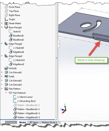
You are now finished with the configuration for “Step 1”. Change to configuration “Step 2” and repeat the process from Step 1 and add the suppression of the next flatten feature:
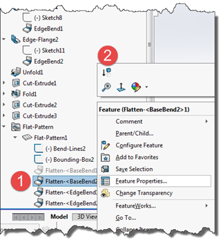
“Step 2” configuration is now complete. Now do the same for the next bend with Configuration
“Step 3” active to get the next set of bends to show.
Once this is done, switch to the “Folded” configuration to get the completed part to show:
Now that all the configurations are created, save the model and start a new drawing.
- Insert Model view and select the “next” arrow.
- Select the “Flat” configuration
- Select the View you saved earlier
- Place view
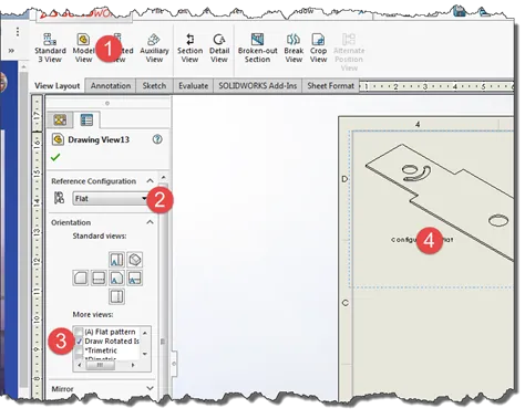
Now create a separate a view using each created configuration as the referenced configuration show in that view.