SOLIDWORKS Simulation: Soft Springs and Inertial Relief
Simulation Tips: Restrain Your Model Before Restraining Yourself
Have you ever leaned back on the backrest of your chair, and then realize that you didn’t have a backrest? Though this “simulation” can be comedic for onlookers, if you try to simulate this type of event using a Static analysis (included in SolidWorks Simulation) you will either a get an error messages, or it will send your model into outer space. So how do you stabilize your model?

Figure 1 – “Unstable model” errors
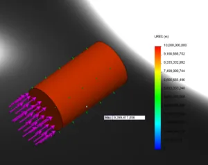
Figure 2 – Under restrained model on its way to the Sun
In order to stabilize your model, you can do one of three things:
- Restrain your model using additional Fixtures, Connections, and even External Loads (“Remote Load/Mass” option can behave like a restraint; Figure 3)
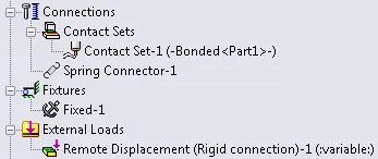
Figure 3 – Restraints
- Enable “Use soft spring to stabilize model” (Figure 4)
- Enable “Inertial Relief” (Figure 4)
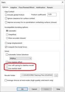
Figure 4 – Study Properties
So what do these two options actually do?
“Use soft spring to stabilize model”
When enabled, this option basically surrounds the model with soft springs to hold it in place. How soft are they? Technically, the following stiffness value is used for the soft springs (Direct Sparse solver on a 2nd order mesh):
approximately 1.1 [OUNCES] per [FOOT] per [one million NODES]
or in SI units since its more precise:
1e-6 [NEWTONS] per [METER] per [NODE]
The net result is that springs exert enough force that it should stabilize the model if there are any small imbalances, but they typically don’t apply enough force to noticeably influence your results. An interesting thing to note is that the total amount of force applied by the springs is related to the number of nodes in your mesh. This means that a fine mesh will add more artificial stiffness to your model if you enable this option. If you are working with a combination of small forces, fine meshes and large displacements you could potentially see large errors from enabling this option.
“Use Inertial Relief”
This option also stabilizes your model, but instead of applying a balancing force through the stiffness of “springs”, it applies a “gravity-like” acceleration to your model to counteract your load. The following image (Figure 5) shows the affect of this balance on a simple model in tension. To see this in more detail, see my video explanation here.
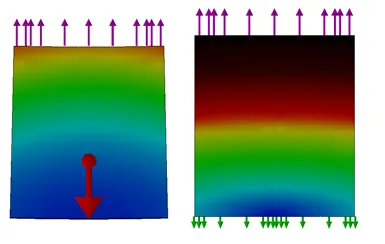
Figure 5 – Displacements on Load + Inertial Relief (left) compared to traditional Load + Fixture (right) no the same model
Using Inertial relief in conjunction with Fixtures is NOT recommended (Figure 6), since the forces from the inertial relief are applied alongside the stabilizing load that a fixture applies, and thus may drastically affect your results. Instead, it is recommended to only apply inertial relief when anticipated forces applied by Fixtures are small or zero, and when the model is balanced by External Loads (with few exceptions).
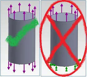
Figure 6 – Left: External Load Balanced (Inertial Relief recommended);
Right: Not External Load Balanced (Inertial Relief NOT recommended)
Likely one of the most practical uses of inertial relief is to balance loads which are imported from SOLIDWORKS Motion.
Conclusion
Overall, my recommendation for any user of SOLIDWORKS Simulation is to run your own simple experiments with these two options with a simple version of your model. This should give you the best idea of how these options affect the results that are of interest to you.

About Shaun Bentley
Shaun Bentley is passionate about applied mathematics and engineering, which led him to pursue and understand real world applications of FEA, CFD, kinematics, dynamics, and 3D & 2D modeling. He teaches many simulation classes to both new and advanced users attending training at GoEngineer. Since 2006, Shaun has been working with simulation tools to solve real world engineering problems. With every new project, he seeks to find ways to push simulation to its uppermost limits, even going so far as to write bespoke code and macros. He has passed the Michigan FE exam and mentors or consults for virtually any industry that uses SOLIDWORKS, especially automotive and automated tools. He is a speed 3D modeling champion and one of the first Certified SOLIDWORKS Experts in Simulation in the world.
Get our wide array of technical resources delivered right to your inbox.
Unsubscribe at any time.