How to Make a Helix in SOLIDWORKS
One of the most common reasons for making a helix is to cut threads into a model. That’s precisely what I’m going to cover today. I'm going to show you how to make a helix in SOLIDWORKS. In my next blog, we'll take that helix and use it to cut threads. Let’s get started.
Creating a Constant Pitch Helix
I’m going to begin by taking my hex cap screw that I modeled previously and I’m going to create a shaft coming off of it. If I look at the specifications sheet, the shaft diameter should be .250 for a ¼ 20 hex cap screw. I’m going to then extrude that out to a height of 1.5 inches.
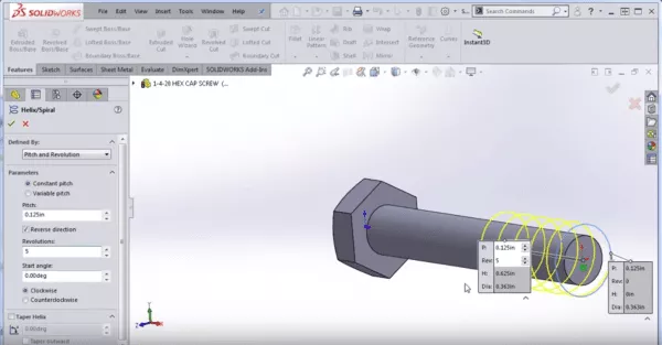
Next, I am going to begin a new sketch and create a circle. I’m going to sketch a circle because this is the starting point for any helix you make in SOLIDWORKS. After you create that circle you can go to the command Features > Curves > Helix and Spiral . From within the helix command, we can designate what we want the height and pitch to be, the pitch and revolution, or the height and revolution.

Let’s say we control pitch and revolution and we make the pitch .125. We'll set the number of revolutions to five. You can see we also have control over the start angle, vertical helix direction, rotational direction, and even something called a variable pitch helix.
Creating a Variable Pitch Helix
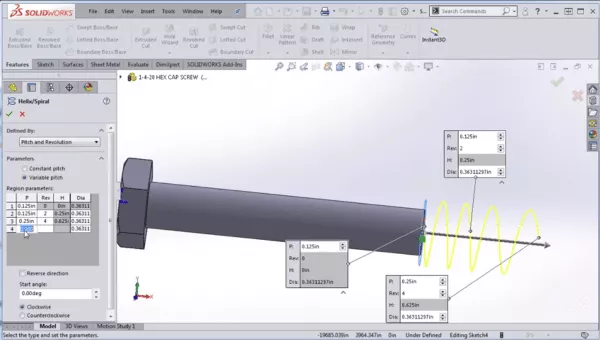
With a variable pitch helix, what we do, is we say we want the pitch to be at .125 for the first two revolutions. Then, as we go from 2 revolutions to 4 revolutions, we’re going to say that we want the pitch to increase to .250. You can see here that it’s no longer holding a constant pitch. Then we can say from 4 revolutions to 6 revolutions, we want it to remain at .250.

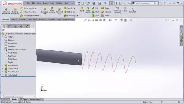
So, now you can see that we end up with a spring that’s compressing on one end or there could be a number of applications for creating a variable pitch helix.

In this example, I’m going to make a constant pitch helix so I can cut some threads into the hex cap screw. So I’ll select a face and sketch a circle. However, I'm not going to use the circle sketch command.
Instead, we want our circle to be an exact duplicate of the top edge of the model, so I’m going to click on the top edge of the model and I’m going to choose Convert Entities. That gives us an exact duplicate of the top edge of the model in the form of a sketched circle. Now, you can go to the command Features > Curves > Helix and Spiral.
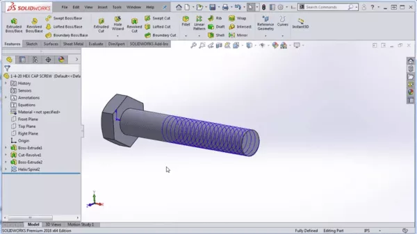
In this case, I don’t want to use Variable Pitch, I want to use Constant Pitch. If it’s not going in the correct direction, you can select Reverse Direction and add the pitch amount (in my case 1/20 because I’m making ¼ 20 hex cap screw). As for the number of revolutions, I want mine to go to 1 inch, so under Defined By, instead of Pitch and Revolution, I’m going to select Height and Pitch and select the height to 1 inch. So now, I have an inch-and-a-half-long shaft with 1 inch of threading.
You can also control your start angle here. I’m going to leave mine at zero. My threading is going to be in the clockwise direction since it’s a standard thread and you don’t want to taper at all while you’re creating your helix. Once it looks good, go ahead and hit the green check mark and that’s it! That’s how to make a helix in SOLIDWORKS.

In my next blog, I’m going to demonstrate how to make threads in SOLIDWORKS and how to cut threads along this helix using a swept cut .
Professional SOLIDWORKS Training from GoEngineer
Learn more about the essential modeling techniques in SOLIDWORKS in our SOLIDWORKS Essentials training courses. These courses are offered in person, live over the web, or on-demand.

About GoEngineer
GoEngineer delivers software, technology, and expertise that enable companies to unlock design innovation and deliver better products faster. With more than 40 years of experience and tens of thousands of customers in high tech, medical, machine design, energy and other industries, GoEngineer provides best-in-class design solutions from SOLIDWORKS CAD, Stratasys 3D printing, Creaform & Artec 3D scanning, CAMWorks, PLM, and more
Get our wide array of technical resources delivered right to your inbox.
Unsubscribe at any time.