How to engrave text on a curved surface

Article by GoEngineer on Jul 28, 2019

There are many occasions that will require engraving on curved surfaces and if you haven’t done it before it can be a bit confusing. We will go step by step on the process of creating a Curve Project feature.

  • Sketch Annotation
  • Curve Feature Selection
  • Add a Multi Surface Feature
  • Create Curve Project Feature
  • Add Engrave/Curve Feature

Sketch Annotation

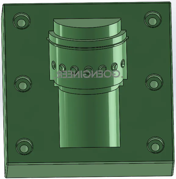
To be able to use the feature, there must be a sketch that it can use. I have a sketched annotation that I want engraved named “GOENGINEER” below in Figure 1.
engrave a sketch annotation

Figure 1: “GOENGINEER” Sketch Annotation that will be engraved

Curve Feature Selection

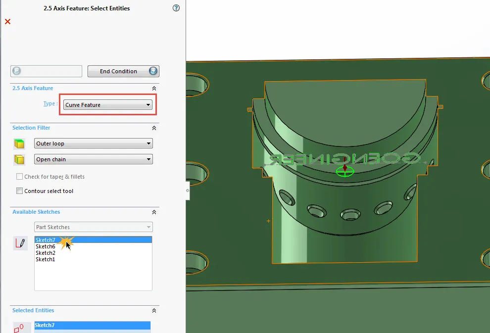
Now create a new 2.5 axis feature and select “Curve Feature” for the feature type, then select the sketch that you want engraved.  Note:  The End condition depth does not matter as it will be specified later. Figure 2 shows the 2.5 Axis Feature dialog box.

2.5 axis feature

Figure 2: 2.5 Axis Feature dialog box

Add a Multi Surface Feature

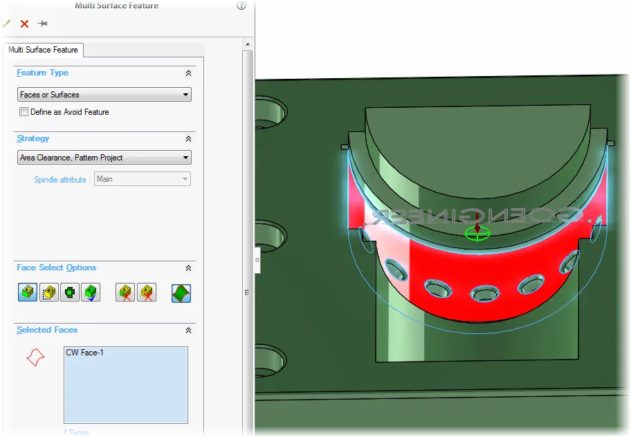
Now that the Curve Feature has been created you will need to create a “Multi Surface Feature.” You can leave it on the default “Area Clearance, Pattern Project” strategy, then select the surface you want to engrave the sketch onto. Figure 3 shows the Multi Surface Feature dialog box.

multi-surface feature dialogue box

Figure 3: Multi Surface Feature dialog box

Create Curve Project Feature

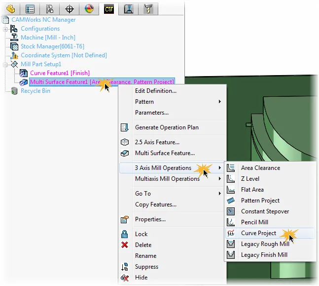
Now that you have a “Curve Feature” and a “Multi Surface Feature,” a “Curve Project” feature needs to be added. To do this, right click on the Multi Surface Feature > 3 Axis Mill Operations > Curve Project. Figure 4 displays the process.

creating a curve feature project

Figure 4: Creating a Curve Project feature.

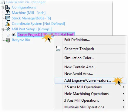
You will then see a “Curve Project” feature in your “Operations” tab. Now right click on the “Curve Project” feature and select “Add Engrave/Curve Feature.” Figure 5 shows where the “Add Engrave/Curve Feature” is located.

curved surface add engrave

Figure 5: Shows Add Engrave/Curve Feature location.

Add Engrave/Curve Feature

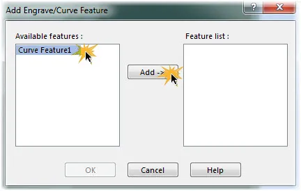
A new window will appear prompting you to select which feature(s) you want to add to the Curve Project feature. Here you will select what features you want added. Select a feature, select “Add” then select “OK.” Figure 6 Shows the window that appears that you use to select the features you want to add to the Curve Project feature.

display section window

Figure 6: Displays selection window for features you want added to the Curve Project.

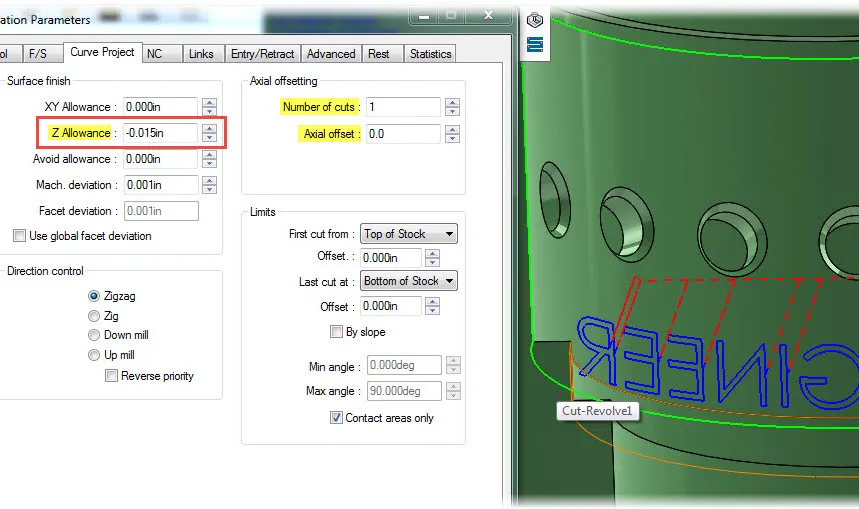
You now have created a “Curve Project” feature but there’s still some editing necessary. You need to edit the definition of the “Curve Project” feature and open the “Curve Project” tab. You will now set the depth of cut by entering an amount in the “Z Allowance” field under the “Surface finish” section. You can also use multiple passes and take a specified depth of cut per pass by changing the “Number of cuts” and entering the cut amount per pass in the “Axial offset” field in the “Axial offsetting” section. Figure 7 Shows the areas that need to be edited to get the correct amount and depth of cut.

fields that need to be edited

Figure7: Fields that need to be edited for correct amount and depth of cut.


About GoEngineer

GoEngineer delivers software, technology, and expertise that enable companies to unlock design innovation and deliver better products faster. With more than 40 years of experience and tens of thousands of customers in high tech, medical, machine design, energy and other industries, GoEngineer provides best-in-class design solutions from SOLIDWORKS CAD, Stratasys 3D printing, Creaform & Artec 3D scanning, CAMWorks, PLM, and more

View all posts by GoEngineer